
boiler safety valve testing procedure in stock

When I teach my steam classes, I ask the attendees, "Do you test the pop safety valve?" Most do not. When I ask why, they tell me the same reason; the safety valve will leak. I joke during the classes that you do not want to test the pop safety valve on a Friday afternoon because it will almost certainly leak. I then ask, Do you check the low water cutoff? They look at me like I have a third eye and say they always check the low water cutoff. If you test the low water cutoff, you should test the pop safety valve. It is the last line of defense against a potential catastrophe. One of the things I do when performing a boiler service call is to explain the duty of the pop safety valve and ask the customer if they would like to have it tested. I explain that it could leak and if they refuse to test it, I will notate it on my service call in case something happens. In this way, my company is protected.
The best way to understand the pop safety valve is to read the instructions which came with the valve. I don"t have a life, and while you are watching the Masked Singer, I read O & M manuals. I know, I"m weird. I figure it"s my job to share things I find while reading these page-turners. The manufacturer hides all sorts of useful tidbits on the installation and maintenance of their valve. I have enclosed some information I gleaned while reading the instructions for a Conbraco/Apollo pop safety valve.
The valve must be mounted in a vertical, upright position directly to a clean, tapped opening in the top of the boiler. I see many safety valves installed horizontally and wonder if that voids the warranty. There should be no restrictions or valves in the piping to or from the safety valve. The installation instructions require the discharge piping to be schedule 40 pipe. They specifically say not to use schedule 80 pipe, which is 50% thicker than schedule 40 pipe. Many installers use copper tubing for the discharge, which does not meet the instructions. The other thing which confuses me the manufacturer instructs you not to use a pipe wrench to install the safety valve. I would wager 99% of all valves are installed using a pipe wrench. I wonder what kind of valve they want you to use.
I consult the pop safety manufacturer or the building insurance company to determine the frequency of tests. Apollo recommends quarterly testing using the Try Lever Test unless the valve is located in a severe service condition, and then it should be done more often. They further state the pop safety valve should have a Pressure Test annually before the heating season or at the end of any non-service period. This test will check your courage as you have to jump out the pressure controls and watch the operation of the boiler as the pressure builds. If the pop safety valve opens at the set pressure, the valve is working properly. This is not a test a novice should do alone.
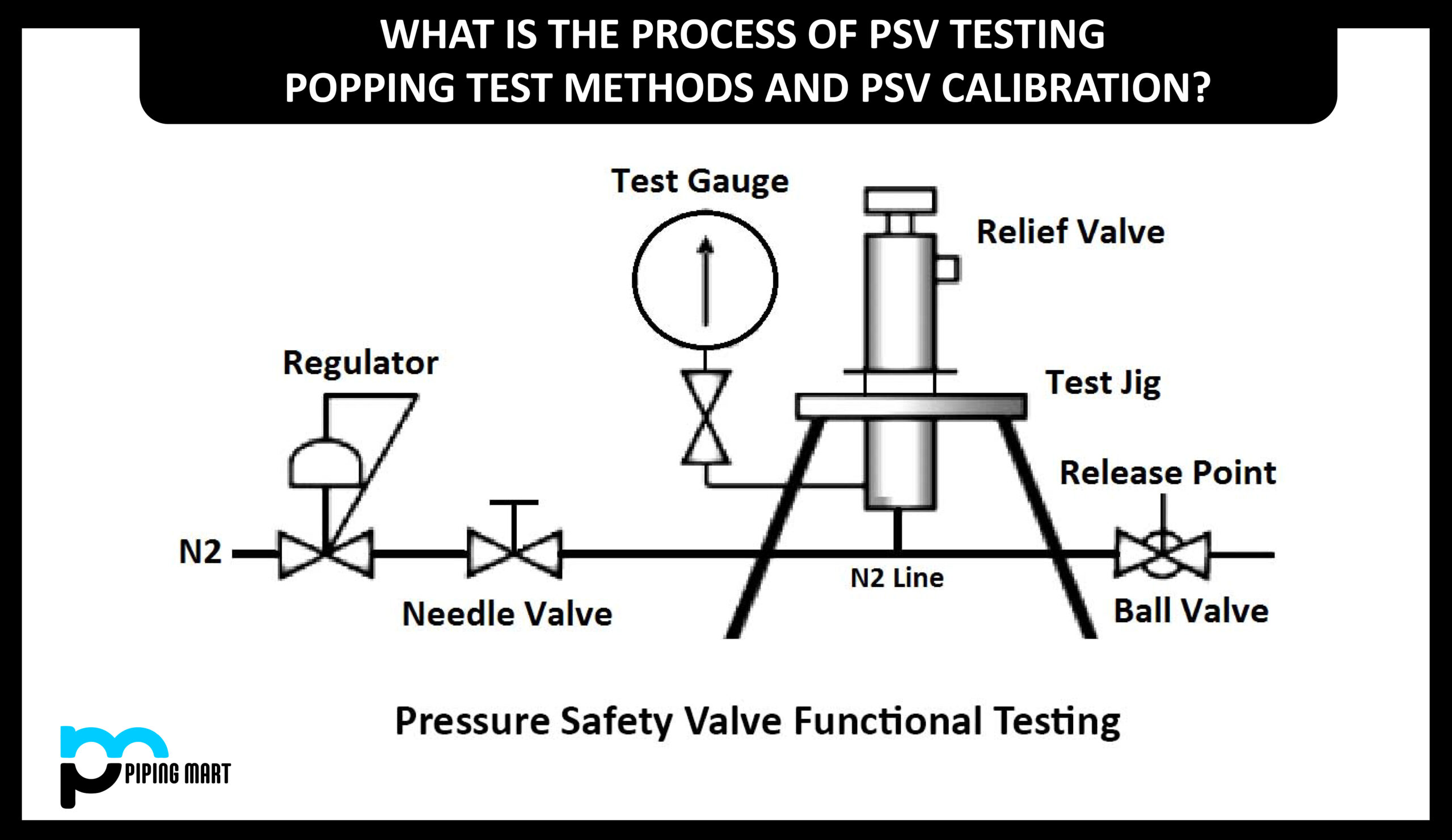
Apollo suggests checking the pop safety valve at or near the maximum operating pressure by holding the test lever fully open for at least 5 seconds and letting it pop closed. On a low-pressure steam system, the pop safety valve is set for 15 psi. I like to run the boiler steam pressure up to 12 psi or higher to check the pop safety valve. After the test, I drop it to the operating pressure the owner requires. If the valve does not open, the boiler should be shut down until it is checked by a licensed contractor or qualified service person.
The pop safety manufacturer requires a minimum pressure differential of five psi between the pressure relief valve set pressure and the boiler operating pressure. It further states, Under no circumstances should the margin be less than five psig. On a low-pressure steam boiler, the pop safety valve will be set for 15 psi. That means the boiler steam pressure should be ten psi or lower. In breweries, it is common to see the boiler pressure set at 12-14 psi. This is less than the five psi differential and could create a dangerous condition.

Testing the safety relief valve is extremely important to the overall safety of your boiler system. In this post, we’ll be talking about what goes into testing a steam relief valve, but safety valve repairs should only be performed by a company holding a current Certificate of Authorization (VR) from the National Board of Pressure Vessel Inspectors.
Using certified and calibrated gauges is essential to accurate testing. WARE’s own Rick Walker recommends using two gauges, for maximum accuracy and in case one isn’t properly functioning.
Relief valves need to open and close at very specific pressures, and also need to open smoothly. A smooth opening contains a clean “pop” sound, and not a simmering or chattering sound. Responding to the appropriate pressures and opening and closing cleanly are both important signs a professional maintenance provider will look for in a safety valve.
Safety valves contain a compression screw, which puts pressure on a spring and causes the valve to function. The compression screw is where a maintenance provider will try to dial in your valve’s functionality and make set-pressure adjustments. It’s important to note if a valve is cold it might test higher, but as the valve gets hotter its metal will expand and its innerspring will slightly decompress.
Once the valve is warm and has stabilized, it’s best to give it more than one test (Rick does three) to make sure the valve is consistent and within ASME code.
ASME defines a safety valve as properly functioning at 150 psi if it tests within 3% of the set pressure. If your valve tests within 3% of the set pressure three times in a row on properly calibrated gauges, you’re likely good to go.
Remember, this procedure should only be done by professionals. If you’d like to schedule maintenance for your boiler, need assistance, or just want to learn more, contact us and check out our maintenance and service options at https://www.wareinc.com/boiler-services
Tired of keeping track of your valve inventory’s annual certification records? We offer complete management of your safety relief valves. With an inventory of repair parts and in stock relief valves of all sizes, we can respond to any customer emergency. We offer annual certification services as well as repair of all major brands, including Kunkle, Conbraco, Consolidated, Dresser, Apollo and more.

Inspection tags are useful tools that help to facilitate and ensure that proper inspection procedures are followed for equipment such as boilers, industrial pressure vessels, and valves. Inspection tags can be used to inform employees when inspection was last conducted on a part or piece of equipment, offering confidence that the equipment is in safe and working order.
Inspection tags can also indicate when a part or piece of equipment is scheduled for maintenance or repairs and can also be used to indicate the status of a current maintenance procedure that’s in-process. Finally, they can be used to communicate hazards and cautions in the workplace, such as denoting equipment that must be inspected prior to operation. And regular inspections aren’t only useful for safety; regular inspections, testing, and repair of leaking pressure safety valves, for instance, results in a cost savings for organizations, in addition to providing environmental benefits.
We’ve created this guide to provide a comprehensive understanding of inspection tags for boilers, industrial pressure vessels, valves, and other parts and equipment, outlining the information you need to know to ensure compliance with inspection requirements and appropriate equipment tags.
Regulations pertaining to the inspection and maintenance of equipment such as boilers, pressure relief valves, and industrial pressure vessels are largely issued on the state and local levels. However, some federal agencies have issued guidance and standards in an effort to guide state and local entities in creating appropriate regulatory requirements. These federal agencies include:
ASME issues standards on testing pressure relief devices and also offers accreditation for laboratories that test pressure relief devices. Additionally, ASME issues standards for the inspection, repair, and alteration of boilers as well as for various types of valves, such as flanged, threaded, and welding end valves.
The Unified Facilities Criteria (UFC), issued by the Department of Defense, offers guidance on the inspection and certification of boilers and unfired pressure vessels, covering the procedures necessary to determine the material condition of this equipment in order to ensure safe, reliable, and efficient operation. It also specifies the frequency of inspection and testing required, the specific items and components that must be tested or inspected, and the forms that must be used.
The National Board of Boiler and Pressure Vessel Inspectors outlines the specific steps required in order to prepare a boiler or pressure vessel for inspection, as well as specific tests and inspection activities to be carried out by inspectors. The American Petroleum Institute issues several standards related to the testing and inspection (and related topics) of pressure relief valves and other equipment, including API Standard 527, Seal Tightness of Pressure Relief Valves, API Standard 620: Design and Construction of Large, Welded, Low-pressure Storage Tanks, and API Standard 526: Flanged Steel Pressure Relief Valves, among others.
According to OSHA, most pressure and storage vessels in use in the United States are designed and constructed in accordance with either ASME Code (or Section VIII of the ASME “Boiler and Pressure Vessel Code”) or with API Standard 620, which establishes rules for lower pressure vessels which are not covered by the ASME Code. Certification of these vessels can only be performed by trained inspectors with the proper qualifications for each code, and certification requires written tests and practical experience.
Other pressure vessel stamps include U2, Alternative Rules Section VIII, Division 2 (Shop and /or Field) and U3, Manufacturing of High Pressure Vessels (Shop and /or Field). The “UV” symbol is designated by ASME for pressure relief valves.
Note that a Quality Control System must be implemented in accordance with the ASME code quality control manual, with procedures prepared by the manufacturer. Inspection-for-Industry.com offers a useful Inspection and Test Plan for pressure safety valves that can aid in this process. The quality control system (for pressure relief valves, industrial pressure vessels, and boilers, as well as other parts and equipment) should include ongoing inspection and testing plans and procedures – all of which must be documented over time on inspection tags and inspection and testing reports. The inspection procedure is distinct for each equipment type, involving several observations and tests, with each inspection culminating with recording and maintaining the inspection and testing results.
The type of inspection record (safety inspections, general inspection record, or an indicator of the equipment category, such as boiler inspection record or valve inspection record)
In addition to inspection tags intended for documenting the performance of periodic inspections and repairs, most equipment requiring inspections also requires the use of compliance tags for the permanent documentation of important processes or procedures, such as operating or maintenance instructions, inspection procedures, and other essential information. Compliance tags are also printed with the equipment manufacturer, serial or model number, date of manufacture, load rating, or electrical specifications, all of which is essential information for performing equipment inspections. Instructional labels are a similar option, documenting equipment maintenance requirements, operating instructions, or safety instructions.
Other inspection tag materials include vinyl, nylon, stainless steel, and some plastics. When selecting an inspection tag for equipment and parts such as industrial pressure vessels, valves, and boilers, consider the operating environment of the equipment and choose inspection tags constructed of durable materials that can withstand these conditions throughout the life of the asset – or at least for the duration of the tag’s usable life (e.g., four years for inspection tags with pre-printed dates designed to track inspections over a four-year period).
You should also consider the process and procedures your company has in place when equipment fails to pass inspection or repairs or maintenance are needed before the equipment can be operated safely. There are tags designed specifically for these uses, printed on red or yellow card stock to indicate that the equipment is awaiting repairs or maintenance and should not be operated until post-repair or post-maintenance inspection confirms that it can be operated safely.
Some testing procedures must be carried out in highly controlled environments, meaning the equipment must be taken out of service until testing is complete. Have procedures in place and appropriate signage and tags on hand to address such scenarios.
Additionally, consider the frequency requirements for inspections. Generally, parts and equipment with greater hazard potential require more frequent inspections, meaning boilers, industrial pressure vessels, and valves will require more frequent inspection and testing than other equipment that poses less risk to operators (or is less subject to malfunctions with slight changes in operating conditions). Inspection frequency also depends on factors such as service, which can alter the ideal inspection frequency even for parts that have a broadly accepted, general guideline of “at least every five years.” For this reason, inspection frequency should be established on an individual basis, within the context of manufacturer requirements and an analysis of the actual service the part or equipment is in.
Inspection tags for boilers, industrial pressure vessels, and valves are just one component of overall quality control. To ensure regulatory compliance, inspection tags prove useful tools in ensuring that minimum inspection intervals are met and providing an audit trail of prior inspection and testing activities. Choosing the right inspection tags for your application will ensure that this vital documentation remains intact and readable throughout the lifespan of your assets.

Many people probably know that the National Board operates a capacity certification program and a valve repair program where we test many pressure relief devices. I want to talk about the background and requirements of that program and the applicability of our testing data to reliability for industry. As a result of years of testing, we have accumulated a good deal of data that helps us analyze the quality and reliability of the equipment. We want to use the data to determine what industry can expect when they receive a certified pressure relief device, pressure relief valve, or rupture disk device.
Two samples are selected every six years and tested at an ASME-certified lab. All test requirements come from the ASME Boiler and Pressure Vessel Code. Through the code, the National Board has been designated the responsibility to manage and run that certification program using the ASME boiler code rules. National Board inspectors travel to the manufacturers’ sites. We also deal with valve assemblers and rupture disk manufacturers. A big part of their responsibility when visiting the site is to look at the manufacturing, assembly, and test procedures, and make sure we get a good representative sample of what that manufacturer is capable of doing.
In some cases we will actually take valves right from shelf stock, particularly from manufacturers that mass produce their product and have large quantities of valves in stock. One selection technique is to go into the warehouse and say, “Give me one of those and one of those.” Sometimes they will dust off the box, but we are trying to get an accurate sample. Sometimes they are testing a valve they are building for the inspector while he"s there, but in that case they are looking at the assembly and test procedures and trying to see if it’s a good representative sample.
The program for individual design is not meant to be statistical in nature, so we are not testing a certain percentage of devices: just those two products every six years. It may be more than two if a test failure occurs. If there is a failure, the manufacturer has to test two additional samples. If they get past that test and still have a problem, a formal corrective action program is implemented. They have to analyze their failure, report on what happened (the cause), and explain what corrective actions they will take. And potentially, a manufacturer could actually lose the ability to put the code stamp on their product, so it"s an important test. The manufacturers have a lot riding on it because if the product passes, they can produce that valve for a six-year period of time. The tests are conducted at ASME/National Board-certified test labs, which include the National Board Testing Lab in Columbus, Ohio, but there are also about 10 other laboratories that are operated by valve manufacturers and rupture disk manufacturers.
We are involved in an ASME certification process. The labs all compare to one another to show that they can essentially attain the same results; they get the same measured capacity. And when any certification test is done at those labs, our inspector goes to witness the test and ensure it meets our requirements and procedures; so all tests are considered on the same basis. We have collected a lot of test data over the years and I looked for trends and patterns to analyze what the data was telling us.
Slide 5: We analyzed information starting with the year 2000. I chose that year because it gave me a lot of tests, but also the code rules for rupture disk certification went into effect in the "98 code, and by the year 2000, rupture disks were a well-certified device under ASME Code Section 8, and manufacturers had started to certify those devices. So it gave them a wider variety of equipment than we had seen before, because until then we were just testing pressure relief valves, and the non-reclosing devices were not well represented in the formal testing that we did, although they were being used out in the industry. It includes valve repair verification tests.
So although we talked about testing done on new product, as part of the valve repair certification process, the valve repair applicant has to repair several sample valves. Those are sent to a certified test lab and tested to exactly the same procedure that a new device is tested under. And while we always say a goal of the valve repair program is to return the valve to a like-new condition, as far as a user is concerned, if we get a repaired pressure relief valve, you should be able to expect that valve to do exactly what a new valve would do. It"s a certified device to begin with. It"s put through a program to inspect it, repair it as necessary, reset it, and get it back to that like-new condition. So I included all these valve repair verification tests. The typical test program for a repair outfit is doing a steam valve, an air valve, and a water valve, depending on the scope of work. And I threw those into the hopper; I treated those just like any other new valve that would be coming from the manufacturer.
We do tests for research and development projects and informational tests (what we call provisional testing). Provisional testing is the test a manufacturer does when they are first getting their design certified. Those tests are essentially prototypes. They are not valves that have truly gone into production, which doesn"t happen until a two-valve test is performed. So none of that was included, because they are still tweaking their design and getting it to the point at which they think it"s capable of being put through the final tests, and then to the production tests, which are the proof of the pudding.
It doesn"t include what we call investigation tests. I will talk a little bit about some of that test data. We don"t have a lot of it, but we do have enough to draw a couple conclusions, but it"s not indicative of the new product going out the door. Some of the limitations of this information based on the economics represents the lower pressures and smaller sizes of valves. So what we and other test labs can do is go up to three-, four-inch inlet sizes. Our pressures and capacities are necessarily limited because to put a pressure relief valve through a full-flow test, you need a lot of support equipment. We run boilers (we previously ran large air compressors but we"ve switched to a nitrogen system) but we have a lot of capital tied up in that. And as you double the pressure, the costs go up exponentially. So our tests are limited; we don"t do eight- and twelve-inch valves. The theory is that the valves are scaled up appropriately, but most of the testing we do is lower sizes and pressures. Hopefully that reflects more typical industrial equipment. We don"t get super-critical boilers, but there are large numbers of boilers with a 150-pound safety valve, and we have covered those pretty well.
Section III – 12 tests (These Section III valves were likely nuclear valves that got repaired as part of a repair demonstration. We don"t normally test many nuclear valves. They are the same physical equipment as you see in either Section 1 or Section 8.)
This is the bulk of the work we do; a wide variety of all different types of Section 8 pressure relief devices. In regards to test medium used: steam is about 25 percent and air is almost half. Air represents all the industrial gases. And then water tests are at about 25 percent. That represents valves for liquid service.
The test outcomes are based on the criteria we put in our database. After we run a test, we give it a designation as to the outcome of the test. Eighty-five percent of the valves passed. The biggest ones are set pressure failures and failures of capacity, with the next biggest elements, and I will talk a little bit about each category.
What I have is a plot of all the pressure relief valves, looking first at set pressure. Anything we called a failure is a failure to meet the ASME code set pressure tolerance. It"s cut and dried. If you fail it, you have to retest. But what we tried to do is see how wide those failures were, their distribution, and where test failures might potentially affect the pressurized equipment where that valve might be installed.
Slides 11-12: This distribution is the measured set pressure over the nameplate set pressure. The numbers below the 100% line are valves that opened underneath the nameplate set pressure requirement. The little tilted spot in the middle is all the valves that passed. And then as we go up on the right-hand side, those are the valves that failed but where the set pressure was actually high. And that to me is the real area of concern. A valve that opens low indicates an operational issue. But what we don"t want are valves that open high.
One glitch we discovered were a few valves that showed up at 400% above the set pressure. Normally we stop a test essentially at one and a half times the set pressure of the valve.
Occasionally we had some valves where set pressure was in bars, the test pressure was in psi, and if you tried to compare those numbers you didn’t necessarily get the right answer. Then what is the unsafe level? Where should we be concerned? A lot of times when people do this analysis, they will look at the hydrostatic test pressure. I do not believe that is conservative enough. That was good when a pressure vessel or boiler was manufactured.
We did an overload test on it and made sure it was good. But as that equipment goes into service over time, we know it"s degraded and there are other things happening to it. The criteria I used for what I call ‘the real bad actors’ was all of the devices that were over 116 % of the nameplate set pressure. That is the Section 8 overpressure limit for a system with multiple pressure relief devices. And if we get above that, we also reference it in the NBIC as a place for taking up the valve for an inservice test. We are going to stop at that point. I"m concerned with anything above that. So that was my first set of data where I"m thinking these are really not the way we would want them to be.
Then we get to valve capacity. The capacity includes valves that didn"t flow what they were rated to flow. A common cause is when valves are over pressured, they will hit a point where they get a secondary lift, and if someone doesn"t fine tune that valve properly, secondary lift isn"t quite achieved. It’s a test-and-tune issue; it"s not necessarily a design issue, but people really understanding how the equipment works. We do have a number of liquid valves that showed up, and again, if a valve doesn"t meet its rated capacity by the code-specified overpressure, it"s a test failure. But we have a number of liquid valves that would open just above whatever the specified overpressure is, typically 10 percent for a Section 8 valve.
So we did have a number of comments for those. And this also includes rupture disks where the flow resistance, which is the Kr valveor minimum net flow area, did not meet specifications.
Slides 13-14: This is my first graph of the distribution of our valve capacity. These are valves that were designated as failures, and we have the measured capacity divided by what the valve is actually rated for. So you can see, it starts at zero and works its way up. It should end at one but I had two or three tests where we called it a capacity failure, but it actually flowed more than the nameplate. Every so often we do run across valves that are misidentified, and sometimes that can be an issue. What I used as a measuring stick was stuff that was less than half of what it was rated at. That tells me it"s a valve that probably was not just a secondary lift issue. There was something really wrong with it. And that ended up being about a half percent of all the tests that were done.
We had about 1% of tests where we just didn"t have a measured capacity. Many were liquid valves. So we will take that test (the set pressure on those is where it first starts to have a trickling flow) and we will keep increasing the pressure until that valve pops open. And if that pressure occurred more than 10% above the set pressure, that valve was a capacity failure. We had a number of those that were about 12-15% above the set point. That information goes to the manufacturer and it can help them figure out their problem. Those valves were not counted in the case where we knew where they opened. We know that once they did open, they would probably work fine. But if you don"t hit it by that 10%, you have got to go through and do another test and improve your product to make it better. The rupture disk Kr number is used a little bit differently.
Slide 17: We had about two percent of what we reported as blow-down failures. These are not included in the final analysis because in reality we look at blow-down ultimately as more of an operational issue. It"s a concern to the user and to the boiler operator. It took two examples: one, we did have some Section 1 valves that were occasionally flagged. There is a minimum blow-down under Section 1. If it"s less than that, again, it"s a test failure and you have to address it. In most cases the capacity is probably fine in those valves.
Under Section 8 there is a requirement for manufacturers to demonstrate the capability to make certain valves meet a 7% blow-down requirement, and ones that fell in this category were valves that the capacity was fine because we actually do test that in that case, but they could not make that blow-down be less than 7%, which is the Section 8 specification. And that"s only for certain designs that are deemed what we call adjustable.
Slide 18: For whatever reason, they couldn"t adjust it. And in that case, the service condition you see is the valve stayed open a little bit longer. We had about .2 percent that we called failed operation. Mostly this is the adjustment of the lifting lever. It"s a lack of attention to detail when the valve was being put together.
I had about a tenth of a percent of valves that we deemed incorrect lift. This is from valves that are certified primarily in Section 8 where they will have restricted lift design. The manufacturer could make a valve that would pass all the criteria, but if set incorrectly, there would be too much lift and the design would not meet capacity. We don"t want somebody to pass because they put the valve together wrong.
Slide 19: So to summarize, I took what I classified as my bad actors: the set pressures that were more than 16 percent above the set pressure; the valve capacity failures that were less than half; the rupture disk Kr and rupture disk failures to open; and it all adds up to about one percent of our test total. And thus my initial estimate of what"s the reliability of this equipment ultimately to do its overpressure protection job is that it comes to about 99 percent, which is good.
We also compare that to the actual test failures. They were higher, and it obviously shows there is still room for improvement in the industry. We deemed a number of tests ‘investigation tests.’ These were valves that either had been received from chief inspectors in a few cases or received from private organizations to do a test to see if it possibly contributed to an accident.
Slide 20: We had 130 tests. About half of them were not applicable, but about 37 valves actually passed. Some failed set pressures, some failed capacity, a few failed blow-down. In all of the tests I have personally witnessed, the majority of the problems were ultimately due to how it was applied or maintained. I can pick up a valve and look inside the inlet and tell you if it will pass or not. We will put it on the test stand and test it. But if it"s all clogged up with rust or corrosion, or if the outlet is clogged with product, that valve is not capable of doing its job. And it"s nothing to do with how it was built. It was ultimately how it was maintained when it was inservice.
Slides 21-22: Looking at all of this information, what can we take away from it? One, we do want to recognize the value of the ASME code/National Board capacity certification program. It ultimately is a program that makes the manufacturers and organizations toe the line. They have got to work hard to meet the standard, and the standard has some very tight tolerances that are associated with it. They are there for a reason: this is safety equipment. We want it to be available 100 percent of the time. But that tight margin does give us a little bit of leeway. For example, if we get a valve that opens at four percent above the set pressure, that"s not a good thing and we will want the manufacturer to do better than that, but it still is well below the area where potentially we are going to have a problem when that valve goes into service.
Many times those test issues cause the organization to tighten up their procedures, and that"s typically what we find when people have a problem. They report back on their corrective action. A lot of times it"s training. People will look at the service manual and say, “Oh, I adjusted it this way.” They don"t understand what those adjustments mean and don"t make them properly. Perhaps they have to improve their calibration or setting techniques.
To increasing our test capabilities, the National Board Testing Lab has gone through an expansion project. We have up-rated our air testing capabilities specifically. I have also gone through some refitting of our steam system trying to improve our test capabilities. You may be hearing more about that over the next year or so.We are quite proud of the work that"s been done and we hope to improve what we do.
And then, finally, the statistics that we are looking at are new equipment going into service. And the one thing that we don"t account for in this information, other than the stuff we get from the investigation tests, is now once it goes into service, it"s not like wine, it doesn"t get better with age. Ultimately we need to inspect it, we need to look at this equipment periodically and make sure that when the inspections are done, they are not just a visual inspection, but we want to know for pressure relief devices, there needs to be testing associated with that to assure the device is working properly.
Make sure you have good inspection history to know how often we should be looking at these pressure relief devices. Some industry standards have a ten-year inspection period, which to me is way too long, particularly in a lot of the more aggressive services. You really need to look at the pressure relief devices more often because of the important function that they serve. But this preliminary data gives you an idea of how good a valve is once it goes into service, at least from a new product perspective. However, because of the data quirks, I wouldn"t necessarily quote any of this yet and put it into a publication.

As soon as mankind was able to boil water to create steam, the necessity of the safety device became evident. As long as 2000 years ago, the Chinese were using cauldrons with hinged lids to allow (relatively) safer production of steam. At the beginning of the 14th century, chemists used conical plugs and later, compressed springs to act as safety devices on pressurised vessels.
Early in the 19th century, boiler explosions on ships and locomotives frequently resulted from faulty safety devices, which led to the development of the first safety relief valves.
In 1848, Charles Retchie invented the accumulation chamber, which increases the compression surface within the safety valve allowing it to open rapidly within a narrow overpressure margin.
Today, most steam users are compelled by local health and safety regulations to ensure that their plant and processes incorporate safety devices and precautions, which ensure that dangerous conditions are prevented.
The principle type of device used to prevent overpressure in plant is the safety or safety relief valve. The safety valve operates by releasing a volume of fluid from within the plant when a predetermined maximum pressure is reached, thereby reducing the excess pressure in a safe manner. As the safety valve may be the only remaining device to prevent catastrophic failure under overpressure conditions, it is important that any such device is capable of operating at all times and under all possible conditions.
Safety valves should be installed wherever the maximum allowable working pressure (MAWP) of a system or pressure-containing vessel is likely to be exceeded. In steam systems, safety valves are typically used for boiler overpressure protection and other applications such as downstream of pressure reducing controls. Although their primary role is for safety, safety valves are also used in process operations to prevent product damage due to excess pressure. Pressure excess can be generated in a number of different situations, including:
The terms ‘safety valve’ and ‘safety relief valve’ are generic terms to describe many varieties of pressure relief devices that are designed to prevent excessive internal fluid pressure build-up. A wide range of different valves is available for many different applications and performance criteria.
In most national standards, specific definitions are given for the terms associated with safety and safety relief valves. There are several notable differences between the terminology used in the USA and Europe. One of the most important differences is that a valve referred to as a ‘safety valve’ in Europe is referred to as a ‘safety relief valve’ or ‘pressure relief valve’ in the USA. In addition, the term ‘safety valve’ in the USA generally refers specifically to the full-lift type of safety valve used in Europe.
Pressure relief valve- A spring-loaded pressure relief valve which is designed to open to relieve excess pressure and to reclose and prevent the further flow of fluid after normal conditions have been restored. It is characterised by a rapid-opening ‘pop’ action or by opening in a manner generally proportional to the increase in pressure over the opening pressure. It may be used for either compressible or incompressible fluids, depending on design, adjustment, or application.
Safety valves are primarily used with compressible gases and in particular for steam and air services. However, they can also be used for process type applications where they may be needed to protect the plant or to prevent spoilage of the product being processed.
Relief valve - A pressure relief device actuated by inlet static pressure having a gradual lift generally proportional to the increase in pressure over opening pressure.
Relief valves are commonly used in liquid systems, especially for lower capacities and thermal expansion duty. They can also be used on pumped systems as pressure overspill devices.
Safety relief valve - A pressure relief valve characterised by rapid opening or pop action, or by opening in proportion to the increase in pressure over the opening pressure, depending on the application, and which may be used either for liquid or compressible fluid.
In general, the safety relief valve will perform as a safety valve when used in a compressible gas system, but it will open in proportion to the overpressure when used in liquid systems, as would a relief valve.
Safety valve- A valve which automatically, without the assistance of any energy other than that of the fluid concerned, discharges a quantity of the fluid so as to prevent a predetermined safe pressure being exceeded, and which is designed to re-close and prevent further flow of fluid after normal pressure conditions of service have been restored.

A series of anomalies occurred in the boiler room that evening. The steel compression tank for the hydronic loop flooded, leaving no room for expansion. Water will expand at 3% of its volume when heated from room temperature to 180° F. When the burner fired, the expansion of the water increased the system pressure within the boiler. The malfunctioning operating control did not shut off the burner at the set point which caused the relief valve to open.
The brass relief valve discharge was installed with copper tubing piped solid to a 90° ell on the floor and the tubing further extended to the floor drain. The combination of hot water and steam from the boiler caused the discharge copper tubing to expand, using the relief valve as a fulcrum. The expansion of the copper discharge tubing pressing against the floor was enough to crack the brass relief valve, flooding the boiler room. The damage was not discovered until the next morning, several hours after the leak occurred. Thousands of dollars in damage was sustained and luckily no one was injured.
Each boiler requires some sort of pressure relieving device. They are referred to as either a safety, relief or safety relief valve. While these names are often thought of as interchangeable, there are subtle differences between them. According to the National Board of Boiler and Pressure Vessel Inspectors, the following are the definitions of each:
• Safety valve— This device is typically used for steam or vapor service. It operates automatically with a full-opening pop action and recloses when the pressure drops to a value consistent with the blowdown requirements prescribed by the applicable governing code or standard.
• Relief valve— This device is used for liquid service. It operates automatically by opening farther as the pressure increases beyond the initial opening pressure and recloses when the pressure drops below the opening pressure.
• Safety relief valve— This device includes the operating characteristics of both a safety valve and a relief valve and may be used in either application.
• Temperature and pressure safety relief valve— This device is typically used on potable water heaters. In addition to its pressure-relief function, it also includes a temperature-sensing element which causes the device to open at a predetermined temperature regardless of pressure. The set temperature on these devices is usually 210°.
• Relief valve piping— The boiler contractor installed a bushing on the outlet of the safety relief valve. Instead of 1 1/2-in. pipe, the installer used 3/4-in. pipe. When asked about it, he answered that he did not have any 1 1/2-in. pipe but had plenty of 3/4-in. pipe. I explained and then had to show the disbelieving contractor the code that states that the relief valve discharge piping has to be the same diameter as the relief valve outlet (see 2012 International Mechanical Code, 1006.6). By reducing the discharge pipe size, the relieving capacity of the safety valve may not be adequate to properly relieve the pressure inside the boiler, causing a dangerous situation.
The code also states that the discharge material shall be of rigid pipe that is approved for the temperature of the system. The inlet pipe size shall be full diameter of the pipe inlet for the relief valve. Some manufacturers suggest using black iron pipe rather than copper tubing. If using copper, it should have an air space that allows expansion should the relief valve open to avoid the accident that I referenced above. The discharge piping has to be supported and the weight of the piping should not be on the safety relief valve. Valves are not permitted in the inlet piping to or discharge piping from the relief valve. If you are using copper tubing on discharge piping, verify that there is room for expansion.
• Installation— Read the manufacturer’s installation manual as each may have different requirements. For instance, Conbraco requires that the discharge piping must terminate with a plain end and use a material that can handle temperatures of 375° or greater. This will preclude PVC or CPVC pipe for the discharge piping. The instruction manual for its model 12-14 steam relief valve stipulates that you cannot use a pipe wrench to install it. That would be good to know.
I once visited Boiler Utopia as the floor was clean and waxed. All the pipes were covered and exposed pipes were painted. There were large stickers detailing what was inside each pipe as well as directional arrows. Nothing was stacked next to the boilers. Yellow caution lines were painted on the floor around each boiler. I was in heaven. As I walked around the rear of the boiler, something clicked and triggered a warning bell. The discharge of the relief valve piping was about 6 in. from the floor but instead of a plain or angled cut end, the pipe had a threaded pipe cap on the termination. I asked the maintenance person about it and he said that the valve was leaking all over his newly waxed floor and this was the only way he could stop it. When I said that the discharge pipe should not have been threaded, he explained that it was not threaded and he had to take it to the local hardware store to thread it. I informed him that the cap had to be removed. We cut the pipe on an angle to prevent this.
• Steam boiler— Most manufacturers recommend a drip pan ell on the discharge of the steam boiler relief valve to eliminate the weight of the discharge piping on the relief valve. Some codes require the discharge to be vented outdoors.
• Testing— I will ask the attendees in my classes, “How often do you test the relief valves?” Most do not make eye contact and when I follow up with, “Why are they not tested?” I often hear that opening the relief valve will cause it to leak. I suggest that you refer to each manufacturer’s directions for testing. For instance, one will recommend once a year while another recommends twice a year. One manufacturer says, “Safety/relief valves should be operated only often enough to assure they are in good working order.” I am not sure what that even means. You want to also verify the proper test procedure as some will only want the relief valve tested when the boiler is at 75% of the rated pressure or higher of the relief valve.

Pressure safety valves are designed to protect process piping and equipment in case of an overpressure event. TEAM Valve Solutions inspects, tests, repairs and re-certifies safety valves at 17 service centers across three continents, and in our fleet of mobile facilities, all of which are audited under the jurisdiction of relevant governing bodies.
Our solutions cover all major safety valve brands and support our customers through an inventory of spare parts and loose-assembled valves. In addition, our facilities are audited and governed by the National Board of Boiler and Pressure Vessel Inspectors. Testing, repair, and assembly are performed under license and guidelines of NBIC, and ASME Section I and VIII.
To ensure accurate in-line setpoint verification, TEAM Valve Solutions utilizes Trevitest, the pioneering system for validating safety valve performance in Conventional and Nuclear Power plants, as well as in other industrial process facilities.
(1) Boiler safety valves and safety relief valves must be as indicated in PG-67 through PG-73 of section I of the ASME Boiler and Pressure Vessel Code (incorporated by reference; see 46 CFR 52.01-1) except as noted otherwise in this section.
(3) On river steam vessels whose boilers are connected in batteries without means of isolating one boiler from another, each battery of boilers shall be treated as a single boiler and equipped with not less than two safety valves of equal size.
(4) (Modifies PG-70.) The total rated relieving capacity of drum and superheater safety valves as certified by the valve manufacturer shall not be less than the maximum generating capacity of the boiler which shall be determined and certified by the boiler manufacturer. This capacity shall be in compliance with PG-70 of section I of the ASME Boiler and Pressure Vessel Code.
(5) In the event the maximum steam generating capacity of the boiler is increased by any means, the relieving capacity of the safety valves shall be checked by an inspector, and, if determined to be necessary, valves of increased relieving capacity shall be installed.
(6) (Modifies PG-67.) Drum safety valves shall be set to relieve at a pressure not in excess of that allowed by the Certificate of Inspection. Where for any reason this is lower than the pressure for which the boiler was originally designed and the revised safety valve capacity cannot be recomputed and certified by the valve manufacturer, one of the tests described in PG-70(3) of section I of the ASME Boiler and Pressure Vessel Code shall be conducted in the presence of the Inspector to insure that the relieving capacity is sufficient at the lower pressure.
(8) Lever or weighted safety valves now installed may be continued in use and may be repaired, but when renewals are necessary, lever or weighted safety valves shall not be used. All such replacements shall conform to the requirements of this section.
(1) (Modifies PG-68.) Superheater safety valves shall be as indicated in PG-68 of section I of the ASME Boiler and Pressure Vessel Code except as noted otherwise in this paragraph.
(2) The setting of the superheater safety valve shall not exceed the design pressure of the superheater outlet flange or the main steam piping beyond the superheater. To prevent damage to the superheater, the drum safety valve shall be set at a pressure not less than that of the superheater safety valve setting plus 5 pounds minimum plus approximately the normal load pressure drop through the superheater and associated piping, including the controlled desuperheater if fitted. See also § 52.01-95(b) (1).
(3) Drum pilot actuated superheater safety valves are permitted provided the setting of the pilot valve and superheater safety valve is such that the superheater safety valve will open before the drum safety valve.
(1) (Modifies PG-71.) Safety valves shall be installed as indicated in PG-71 of section I of the ASME Boiler and Pressure Vessel Code except as noted otherwise in this paragraph.
(2) The final setting of boiler safety valves shall be checked and adjusted under steam pressure and, if possible, while the boiler is on the line and the steam is at operating temperatures, in the presence of and to the satisfaction of a marine inspector who, upon acceptance, shall seal the valves. This regulation applies to both drum and superheater safety valves of all boilers.
(3) The safety valve body drains required by PG-71 of section I of the ASME Boiler and Pressure Vessel Code shall be run as directly as possible from the body of each boiler safety valve, or the drain from each boiler safety valve may be led to an independent header common only to boiler safety valve drains. No valves of any type shall be installed in the leakoff from drains or drain headers and they shall be led to suitable locations to avoid hazard to personnel.
(1) (Modifies PG-72.) The operation of safety valves shall be as indicated in PG-72 of section I of the ASME Boiler and Pressure Vessel Code except as noted in paragraph (d)(2) of this section.
(2) (Modifies PG-73.) The lifting device required by PG-73.1.3 of section I of the ASME Boiler and Pressure Vessel Code shall be fitted with suitable relieving gear so arranged that the controls may be operated from the fireroom or engineroom floor.

The steam will condenses and partial vacuum occurred and move back the water thealong the pipe with very high velocity, and the water will strike at the vent or valves.
Once being dose into the boiler water floating solid particles and suspended solid are settled tothe bottom of the boiler and easily remove by blowing down.
All safety valves are to be set to operate under steam a little above working pressure not greaterthan 3% above the approve working pressure of the boiler.

If your water heater is not working, you might be in need of heater repair but there are still a few things you can do before contacting your local plumber. One of those things is pressure relief valve testing. What is the proper pressure relief valve testing procedure and should you call for emergency repair immediately? Follow our guide to know all there is to know about boiler pressure relief valve testing.
If: The valve won’t open or no water comes out; the valve drips or doesn’t fully seal after you test it; you notice water pooling below the drainpipe in the future…


 8613371530291