
boiler safety valve testing procedure brands
Distributor of pipe, valves, piping accessories, industrial pumps & valve automation. Fluid handling products such as steam traps, control & high performance valves, corrosion resistant piping & grooved piping systems are also available. Valves include sanitary butterfly, plug, ball, check, gate, globe, sampling & rising stem valves. Instrumentation include actuators, limit switches, instrumentation fittings, transmitter manifolds, low pressure brass fittings, quick connectors, thermometers, gauges, RTDs, thermocouples, temperature & pressure sensors, pressure & temperature regulators, fluid & gas meters & sensors, positive displacement & turbine meters, positioners, switch boxes & pneumatic cylinders. Pumps & process equipment include rotary, positive displacement, air operated double diaphragm, progressive cavity, centrifugal, vertical & horizontal, end suction & submersible pumps.

IVI is a VR certified safety valve repair facility, approved by the National Board of Boiler and Pressure Vessel Inspectors as a VR certificate holder (stamp 179). We certify pressure relief valves in the shop and in the field for sections V and UV. We also perform on-site testing (while the plant operates) providing documented reports for all valves tested. We are also certified to administer special process conversions regarding machining, welding, heat treating, and N.D.T. (non-destructive testing) with our VR certificate.
With our VR stamp, we repair all types of pressure relief valves such as Consolidated, Crosby, Kunkle, Farris, Spence, Anderson Greenwood, and numerous other O.E.M. safety and pressure relief valves.
Vinson understands that complete reliability of all Pressure Relief Devices is essential to protect, not only a plant’s assets, but most importantly all personnel and the environment. Vinson offers both field and in-shop repair services, and is proud to be one of the nation’s leading National Board certified VR & TO Repair Facilities. With certifications on air/gas/liquid and steam service (Section I & VIII), Vinson provides setting, repair and testing services on all manufacturers valves up to 10,000 psi.
Testing the safety relief valve is extremely important to the overall safety of your boiler system. In this post, we’ll be talking about what goes into testing a steam relief valve, but safety valve repairs should only be performed by a company holding a current Certificate of Authorization (VR) from the National Board of Pressure Vessel Inspectors.
Using certified and calibrated gauges is essential to accurate testing. WARE’s own Rick Walker recommends using two gauges, for maximum accuracy and in case one isn’t properly functioning.
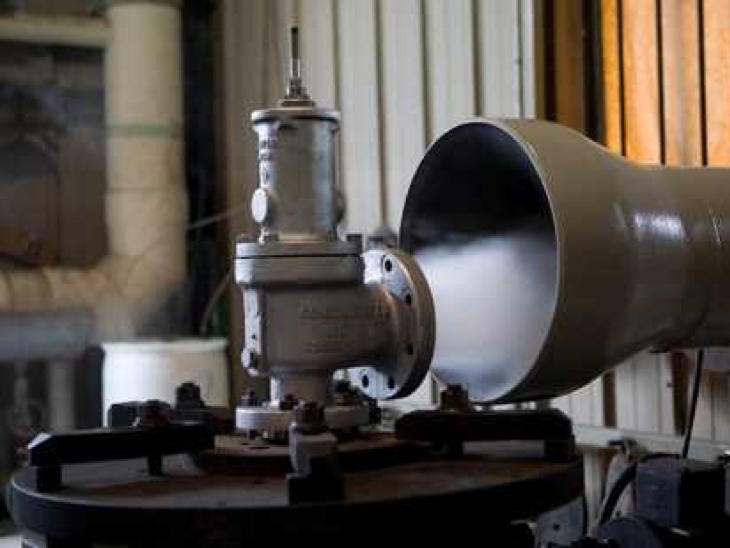
Relief valves need to open and close at very specific pressures, and also need to open smoothly. A smooth opening contains a clean “pop” sound, and not a simmering or chattering sound. Responding to the appropriate pressures and opening and closing cleanly are both important signs a professional maintenance provider will look for in a safety valve.
Safety valves contain a compression screw, which puts pressure on a spring and causes the valve to function. The compression screw is where a maintenance provider will try to dial in your valve’s functionality and make set-pressure adjustments. It’s important to note if a valve is cold it might test higher, but as the valve gets hotter its metal will expand and its innerspring will slightly decompress.
Once the valve is warm and has stabilized, it’s best to give it more than one test (Rick does three) to make sure the valve is consistent and within ASME code.
ASME defines a safety valve as properly functioning at 150 psi if it tests within 3% of the set pressure. If your valve tests within 3% of the set pressure three times in a row on properly calibrated gauges, you’re likely good to go.
Remember, this procedure should only be done by professionals. If you’d like to schedule maintenance for your boiler, need assistance, or just want to learn more, contact us and check out our maintenance and service options at https://www.wareinc.com/boiler-services
Pressure safety valves are designed to protect process piping and equipment in case of an overpressure event. TEAM Valve Solutions inspects, tests, repairs and re-certifies safety valves at 17 service centers across three continents, and in our fleet of mobile facilities, all of which are audited under the jurisdiction of relevant governing bodies.
Our solutions cover all major safety valve brands and support our customers through an inventory of spare parts and loose-assembled valves. In addition, our facilities are audited and governed by the National Board of Boiler and Pressure Vessel Inspectors. Testing, repair, and assembly are performed under license and guidelines of NBIC, and ASME Section I and VIII.
To ensure accurate in-line setpoint verification, TEAM Valve Solutions utilizes Trevitest, the pioneering system for validating safety valve performance in Conventional and Nuclear Power plants, as well as in other industrial process facilities.

Safety is of the utmost importance when dealing with pressure relief valves. The valve is designed to limit system pressure, and it is critical that they remain in working order to prevent an explosion. Explosions have caused far too much damage in companies over the years, and though pressurized tanks and vessels are equipped with pressure relief vales to enhance safety, they can fail and result in disaster.
That’s also why knowing the correct way to test the valves is important. Ongoing maintenance and periodic testing of pressurized tanks and vessels and their pressure relief valves keeps them in working order and keep employees and their work environments safe. Pressure relief valves must be in good condition in order to automatically lower tank and vessel pressure; working valves open slowly when the pressure gets high enough to exceed the pressure threshold and then closes slowly until the unit reaches the low, safe threshold. To ensure the pressure relief valve is in good working condition, employees must follow best practices for testing them including:
If you consider testing pressure relief valves a maintenance task, you’ll be more likely to carry out regular testing and ensure the safety of your organization and the longevity of your
It’s important to note, however, that the American Society of Mechanical Engineers (ASME) and National Board Inspection Code (NBIC), as well as state and local jurisdictions, may set requirements for testing frequency. Companies are responsible for checking with these organizations to become familiar with the testing requirements. Consider the following NBIC recommendations on the frequency for testing relief valves:
High-pressure steam boilers greater than 15 psi and less than 400 psi – perform manual check every six months and pressure test annually to verify nameplate set pressure
High-pressure steam boilers 400 psi and greater – pressure test to verify nameplate set pressure every three years or as determined by operating experience as verified by testing history
High-temperature hot water boilers (greater than 160 psi and/or 250 degrees Fahrenheit) – pressure test annually to verify nameplate set pressure. For safety reasons, removal and testing on a test bench is recommended
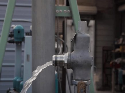
When testing the pressure relief valve, raise and lower the test lever several times. The lever will come away from the brass stem and allow hot water to come out of the end of the drainpipe. The water should flow through the pipe, and then you should turn down the pressure to stop the leak, replace the lever, and then increase the pressure.
One of the most common problems you can address with regular testing is the buildup of mineral salt, rust, and corrosion. When buildup occurs, the valve will become non-operational; the result can be an explosion. Regular testing helps you discover these issues sooner so you can combat them and keep your boiler and valve functioning properly. If no water flows through the pipe, or if there is a trickle instead of a rush of water, look for debris that is preventing the valve from seating properly. You may be able to operate the test lever a few times to correct the issue. You will need to replace the valve if this test fails.
When testing relief valves, keep in mind that they have two basic functions. First, they will pop off when the pressure exceeds its safety threshold. The valve will pop off and open to exhaust the excess pressure until the tank’s pressure decreases to reach the set minimum pressure. After this blowdown process occurs, the valve should reset and automatically close. One important testing safety measure is to use a pressure indicator with a full-scale range higher than the pop-off pressure.
Thus, you need to be aware of the pop-off pressure point of whatever tank or vessel you test. You always should remain within the pressure limits of the test stand and ensure the test stand is assembled properly and proof pressure tested. Then, take steps to ensure the escaping pressure from the valve is directed away from the operator and that everyone involved in the test uses safety shields and wears safety eye protection.
After discharge – Because pressure relief valves are designed to open automatically to relieve pressure in your system and then close, they may be able to open and close multiple times during normal operation and testing. However, when a valve opens, debris may get into the valve seat and prevent the valve from closing properly. After discharge, check the valve for leakage. If the leakage exceeds the original settings, you need to repair the valve.
According to local jurisdictional requirements – Regulations are in place for various locations and industries that stipulate how long valves may operate before needing to be repair or replaced. State inspectors may require valves to be disassembled, inspected, repaired, and tested every five years, for instance. If you have smaller valves and applications, you can test the valve by lifting the test lever. However, you should do this approximately once a year. It’s important to note that ASME UG136A Section 3 requires valves to have a minimum of 75% operating pressure versus the set pressure of the valve for hand lifting to be performed for these types of tests.
Depending on their service and application– The service and application of a valve affect its lifespan. Valves used for clean service like steam typically last at least 20 years if they are not operated too close to the set point and are part of a preventive maintenance program. Conversely, valves used for services such as acid service, those that are operated too close to the set point, and those exposed to dirt or debris need to be replaced more often.
Pressure relief valves serve a critical role in protecting organizations and employees from explosions. Knowing how and when to test and repair or replace them is essential.
Certifies Allied Valve Inc. is qualified and approved to assemble Pressure Relief Valves (PRV) for use in Section I applications including boilers and pressure vessels.
Certifies Allied Valve Inc. is qualified and approved to assemble Pressure Relief Valves (PRV) for use in Section VIII applications including all uses outside of boilers and pressure vessels.
Certifies Allied Valve Inc. is qualified and approved to calibrate, test, and stamp Pressure Relief Valves (PRV) for use in Section I and Section VIII applications.
Certifies Allied Valve Inc. is qualified and approved to repair Pressure Relief Valves (PRV) of all brands for both Section I and Section VIII applications.
The National Board offers the Certificate of Authorization and T/O mark for the inservice testing of pressure relief valves. Requirements are described in NB-528. Accreditation of T/o Test Only Organizations.
Boiler explosions have been responsible for widespread damage to companies throughout the years, and that’s why today’s boilers are equipped with safety valves and/or relief valves. Boiler safety valves are designed to prevent excess pressure, which is usually responsible for those devastating explosions. That said, to ensure that boiler safety valves are working properly and providing adequate protection, they must meet regulatory specifications and require ongoing maintenance and periodic testing. Without these precautions, malfunctioning safety valves may fail, resulting in potentially disastrous consequences.
Boiler safety valves are activated by upstream pressure. If the pressure exceeds a defined threshold, the valve activates and automatically releases pressure. Typically used for gas or vapor service, boiler safety valves pop fully open once a pressure threshold is reached and remain open until the boiler pressure reaches a pre-defined, safe lower pressure.
Boiler relief valves serve the same purpose – automatically lowering boiler pressure – but they function a bit differently than safety valves. A relief valve doesn’t open fully when pressure exceeds a defined threshold; instead, it opens gradually when the pressure threshold is exceeded and closes gradually until the lower, safe threshold is reached. Boiler relief valves are typically used for liquid service.
There are also devices known as “safety relief valves” which have the characteristics of both types discussed above. Safety relief valves can be used for either liquid or gas or vapor service.
Nameplates must be fastened securely and permanently to the safety valve and remain readable throughout the lifespan of the valve, so durability is key.
The National Board of Boiler and Pressure Vessel Inspectors offers guidance and recommendations on boiler and pressure vessel safety rules and regulations. However, most individual states set forth their own rules and regulations, and while they may be similar across states, it’s important to ensure that your boiler safety valves meet all state and local regulatory requirements.
The National Board published NB-131, Recommended Boiler and Pressure Vessel Safety Legislation, and NB-132, Recommended Administrative Boiler and Pressure Vessel Safety Rules and Regulationsin order to provide guidance and encourage the development of crucial safety laws in jurisdictions that currently have no laws in place for the “proper construction, installation, inspection, operation, maintenance, alterations, and repairs” necessary to protect workers and the public from dangerous boiler and pressure vessel explosions that may occur without these safeguards in place.
The American Society of Mechanical Engineers (ASME) governs the code that establishes guidelines and requirements for safety valves. Note that it’s up to plant personnel to familiarize themselves with the requirements and understand which parts of the code apply to specific parts of the plant’s steam systems.
High steam capacity requirements, physical or economic constraints may make the use of a single safety valve impossible. In these cases, using multiple safety valves on the same system is considered an acceptable practice, provided that proper sizing and installation requirements are met – including an appropriately sized vent pipe that accounts for the total steam venting capacity of all valves when open at the same time.
The lowest rating (MAWP or maximum allowable working pressure) should always be used among all safety devices within a system, including boilers, pressure vessels, and equipment piping systems, to determine the safety valve set pressure.
Avoid isolating safety valves from the system, such as by installing intervening shut-off valves located between the steam component or system and the inlet.
Contact the valve supplier immediately for any safety valve with a broken wire seal, as this indicates that the valve is unsafe for use. Safety valves are sealed and certified in order to prevent tampering that can prevent proper function.
Avoid attaching vent discharge piping directly to a safety valve, which may place unnecessary weight and additional stress on the valve, altering the set pressure.

The primary role of a safety relief valve is to prevent over-pressure situations in pressurized vessels or systems. If the tank’s relief valve fails, it can lead to an accident that destroys property, life, or landscape.
The National Board of Boiler and Pressure Vessel Inspectors is one of the governing bodies for the testing and/or repair of ASME Safety Relief Valves.
You, as the owner of the valve, can test it, but it must be done in accordance with the National Board Inspection Code and your state’s and/or local regulations.
Based on the National Board Code, which bases their inspection intervals on what type of service the valve is used for, the following intervals are suggested:
Also, keep in mind that this piping should be oriented so that no liquid relieved through this piping can flow back and rest on the ASME safety relief valve’s outlet port.
The ASME relief valves are set to fully open at its “set” pressure but will begin to partially open before then – normally at 10% below its set pressure.
If your valve is allowed to do this, trash and/or corrosion can set in over time which could prevent the valve from either closing completely or from fully opening, either of which is not a favorable solution.

When I teach my steam classes, I ask the attendees, "Do you test the pop safety valve?" Most do not. When I ask why, they tell me the same reason; the safety valve will leak. I joke during the classes that you do not want to test the pop safety valve on a Friday afternoon because it will almost certainly leak. I then ask, Do you check the low water cutoff? They look at me like I have a third eye and say they always check the low water cutoff. If you test the low water cutoff, you should test the pop safety valve. It is the last line of defense against a potential catastrophe. One of the things I do when performing a boiler service call is to explain the duty of the pop safety valve and ask the customer if they would like to have it tested. I explain that it could leak and if they refuse to test it, I will notate it on my service call in case something happens. In this way, my company is protected.
The best way to understand the pop safety valve is to read the instructions which came with the valve. I don"t have a life, and while you are watching the Masked Singer, I read O & M manuals. I know, I"m weird. I figure it"s my job to share things I find while reading these page-turners. The manufacturer hides all sorts of useful tidbits on the installation and maintenance of their valve. I have enclosed some information I gleaned while reading the instructions for a Conbraco/Apollo pop safety valve.
The valve must be mounted in a vertical, upright position directly to a clean, tapped opening in the top of the boiler. I see many safety valves installed horizontally and wonder if that voids the warranty. There should be no restrictions or valves in the piping to or from the safety valve. The installation instructions require the discharge piping to be schedule 40 pipe. They specifically say not to use schedule 80 pipe, which is 50% thicker than schedule 40 pipe. Many installers use copper tubing for the discharge, which does not meet the instructions. The other thing which confuses me the manufacturer instructs you not to use a pipe wrench to install the safety valve. I would wager 99% of all valves are installed using a pipe wrench. I wonder what kind of valve they want you to use.
I consult the pop safety manufacturer or the building insurance company to determine the frequency of tests. Apollo recommends quarterly testing using the Try Lever Test unless the valve is located in a severe service condition, and then it should be done more often. They further state the pop safety valve should have a Pressure Test annually before the heating season or at the end of any non-service period. This test will check your courage as you have to jump out the pressure controls and watch the operation of the boiler as the pressure builds. If the pop safety valve opens at the set pressure, the valve is working properly. This is not a test a novice should do alone.
Apollo suggests checking the pop safety valve at or near the maximum operating pressure by holding the test lever fully open for at least 5 seconds and letting it pop closed. On a low-pressure steam system, the pop safety valve is set for 15 psi. I like to run the boiler steam pressure up to 12 psi or higher to check the pop safety valve. After the test, I drop it to the operating pressure the owner requires. If the valve does not open, the boiler should be shut down until it is checked by a licensed contractor or qualified service person.
The pop safety manufacturer requires a minimum pressure differential of five psi between the pressure relief valve set pressure and the boiler operating pressure. It further states, Under no circumstances should the margin be less than five psig. On a low-pressure steam boiler, the pop safety valve will be set for 15 psi. That means the boiler steam pressure should be ten psi or lower. In breweries, it is common to see the boiler pressure set at 12-14 psi. This is less than the five psi differential and could create a dangerous condition.

The National Board offers the Certificate of Authorization and VR Stamp for the repair of pressure relief valves. Requirements are included in the current mandatory edition of the National Board Inspection Code(NBIC), Part 4, and NB-514, Accreditation of VR Repair Organizations.
The National Board offers the Certificate of Authorization for use of the T/O mark which indicates accreditation as a pressure relief valve Testing Organization. The program includes provisions for minor adjustments to restore valve performance. Requirements are based upon the current mandatory edition of the National Board Inspection Code(NBIC), Part 2, Part 4, and NB-528, Accreditation of T/O Test Only Organizations.
The National Board supports members who request tests be conducted on pressure relief devices involved in boiler and pressure vessel accidents. This service is provided at no cost to the National Board member. Please contact Pressure Relief or Executive staff for more information.
Representatives from the National Board are assigned to visit company sites to select production sample valves for testing at National Board- and ASME- accepted labs.

As soon as mankind was able to boil water to create steam, the necessity of the safety device became evident. As long as 2000 years ago, the Chinese were using cauldrons with hinged lids to allow (relatively) safer production of steam. At the beginning of the 14th century, chemists used conical plugs and later, compressed springs to act as safety devices on pressurised vessels.
Early in the 19th century, boiler explosions on ships and locomotives frequently resulted from faulty safety devices, which led to the development of the first safety relief valves.
In 1848, Charles Retchie invented the accumulation chamber, which increases the compression surface within the safety valve allowing it to open rapidly within a narrow overpressure margin.
Today, most steam users are compelled by local health and safety regulations to ensure that their plant and processes incorporate safety devices and precautions, which ensure that dangerous conditions are prevented.
The principle type of device used to prevent overpressure in plant is the safety or safety relief valve. The safety valve operates by releasing a volume of fluid from within the plant when a predetermined maximum pressure is reached, thereby reducing the excess pressure in a safe manner. As the safety valve may be the only remaining device to prevent catastrophic failure under overpressure conditions, it is important that any such device is capable of operating at all times and under all possible conditions.
Safety valves should be installed wherever the maximum allowable working pressure (MAWP) of a system or pressure-containing vessel is likely to be exceeded. In steam systems, safety valves are typically used for boiler overpressure protection and other applications such as downstream of pressure reducing controls. Although their primary role is for safety, safety valves are also used in process operations to prevent product damage due to excess pressure. Pressure excess can be generated in a number of different situations, including:
The terms ‘safety valve’ and ‘safety relief valve’ are generic terms to describe many varieties of pressure relief devices that are designed to prevent excessive internal fluid pressure build-up. A wide range of different valves is available for many different applications and performance criteria.
In most national standards, specific definitions are given for the terms associated with safety and safety relief valves. There are several notable differences between the terminology used in the USA and Europe. One of the most important differences is that a valve referred to as a ‘safety valve’ in Europe is referred to as a ‘safety relief valve’ or ‘pressure relief valve’ in the USA. In addition, the term ‘safety valve’ in the USA generally refers specifically to the full-lift type of safety valve used in Europe.
Pressure relief valve- A spring-loaded pressure relief valve which is designed to open to relieve excess pressure and to reclose and prevent the further flow of fluid after normal conditions have been restored. It is characterised by a rapid-opening ‘pop’ action or by opening in a manner generally proportional to the increase in pressure over the opening pressure. It may be used for either compressible or incompressible fluids, depending on design, adjustment, or application.
Safety valves are primarily used with compressible gases and in particular for steam and air services. However, they can also be used for process type applications where they may be needed to protect the plant or to prevent spoilage of the product being processed.
Relief valve - A pressure relief device actuated by inlet static pressure having a gradual lift generally proportional to the increase in pressure over opening pressure.
Relief valves are commonly used in liquid systems, especially for lower capacities and thermal expansion duty. They can also be used on pumped systems as pressure overspill devices.
Safety relief valve - A pressure relief valve characterised by rapid opening or pop action, or by opening in proportion to the increase in pressure over the opening pressure, depending on the application, and which may be used either for liquid or compressible fluid.
In general, the safety relief valve will perform as a safety valve when used in a compressible gas system, but it will open in proportion to the overpressure when used in liquid systems, as would a relief valve.
Safety valve- A valve which automatically, without the assistance of any energy other than that of the fluid concerned, discharges a quantity of the fluid so as to prevent a predetermined safe pressure being exceeded, and which is designed to re-close and prevent further flow of fluid after normal pressure conditions of service have been restored.

There is a wide range of safety valves available to meet the many different applications and performance criteria demanded by different industries. Furthermore, national standards define many varying types of safety valve.
The ASME standard I and ASME standard VIII for boiler and pressure vessel applications and the ASME/ANSI PTC 25.3 standard for safety valves and relief valves provide the following definition. These standards set performance characteristics as well as defining the different types of safety valves that are used:
ASME I valve - A safety relief valve conforming to the requirements of Section I of the ASME pressure vessel code for boiler applications which will open within 3% overpressure and close within 4%. It will usually feature two blowdown rings, and is identified by a National Board ‘V’ stamp.
ASME VIII valve- A safety relief valve conforming to the requirements of Section VIII of the ASME pressure vessel code for pressure vessel applications which will open within 10% overpressure and close within 7%. Identified by a National Board ‘UV’ stamp.
Full bore safety valve - A safety valve having no protrusions in the bore, and wherein the valve lifts to an extent sufficient for the minimum area at any section, at or below the seat, to become the controlling orifice.
Conventional safety relief valve -The spring housing is vented to the discharge side, hence operational characteristics are directly affected by changes in the backpressure to the valve.
Balanced safety relief valve -A balanced valve incorporates a means of minimising the effect of backpressure on the operational characteristics of the valve.
Pilot operated pressure relief valve -The major relieving device is combined with, and is controlled by, a self-actuated auxiliary pressure relief device.
Power-actuated safety relief valve - A pressure relief valve in which the major pressure relieving device is combined with, and controlled by, a device requiring an external source of energy.
Standard safety valve - A valve which, following opening, reaches the degree of lift necessary for the mass flowrate to be discharged within a pressure rise of not more than 10%. (The valve is characterised by a pop type action and is sometimes known as high lift).
Full lift (Vollhub) safety valve -A safety valve which, after commencement of lift, opens rapidly within a 5% pressure rise up to the full lift as limited by the design. The amount of lift up to the rapid opening (proportional range) shall not be more than 20%.
Direct loaded safety valve -A safety valve in which the opening force underneath the valve disc is opposed by a closing force such as a spring or a weight.
Proportional safety valve - A safety valve which opens more or less steadily in relation to the increase in pressure. Sudden opening within a 10% lift range will not occur without pressure increase. Following opening within a pressure of not more than 10%, these safety valves achieve the lift necessary for the mass flow to be discharged.
Diaphragm safety valve -A direct loaded safety valve wherein linear moving and rotating elements and springs are protected against the effects of the fluid by a diaphragm
Bellows safety valve - A direct loaded safety valve wherein sliding and (partially or fully) rotating elements and springs are protected against the effects of the fluids by a bellows. The bellows may be of such a design that it compensates for influences of backpressure.
Controlled safety valve - Consists of a main valve and a control device. It also includes direct acting safety valves with supplementary loading in which, until the set pressure is reached, an additional force increases the closing force.
Safety valve - A safety valve which automatically, without the assistance of any energy other than that of the fluid concerned, discharges a quantity of the fluid so as to prevent a predetermined safe pressure being exceeded, and which is designed to re-close and prevent further flow of fluid after normal pressure conditions of service have been restored. Note; the valve can be characterised either by pop action (rapid opening) or by opening in proportion (not necessarily linear) to the increase in pressure over the set pressure.
Direct loaded safety valve -A safety valve in which the loading due to the fluid pressure underneath the valve disc is opposed only by a direct mechanical loading device such as a weight, lever and weight, or a spring.
Assisted safety valve -A safety valve which by means of a powered assistance mechanism, may additionally be lifted at a pressure lower than the set pressure and will, even in the event of a failure of the assistance mechanism, comply with all the requirements for safety valves given in the standard.
Supplementary loaded safety valve - A safety valve that has, until the pressure at the inlet to the safety valve reaches the set pressure, an additional force, which increases the sealing force.
Note; this additional force (supplementary load), which may be provided by means of an extraneous power source, is reliably released when the pressure at the inlet of the safety valve reaches the set pressure. The amount of supplementary loading is so arranged that if such supplementary loading is not released, the safety valve will attain its certified discharge capacity at a pressure not greater than 1.1 times the maximum allowable pressure of the equipment to be protected.
Pilot operated safety valve -A safety valve, the operation of which is initiated and controlled by the fluid discharged from a pilot valve, which is itself, a direct loaded safety valve subject to the requirement of the standard.
The common characteristic shared between the definitions of conventional safety valves in the different standards, is that their operational characteristics are affected by any backpressure in the discharge system. It is important to note that the total backpressure is generated from two components; superimposed backpressure and the built-up backpressure:
Subsequently, in a conventional safety valve, only the superimposed backpressure will affect the opening characteristic and set value, but the combined backpressure will alter the blowdown characteristic and re-seat value.
The ASME/ANSI standard makes the further classification that conventional valves have a spring housing that is vented to the discharge side of the valve. If the spring housing is vented to the atmosphere, any superimposed backpressure will still affect the operational characteristics. Thiscan be seen from Figure 9.2.1, which shows schematic diagrams of valves whose spring housings are vented to the discharge side of the valve and to the atmosphere.
By considering the forces acting on the disc (with area AD), it can be seen that the required opening force (equivalent to the product of inlet pressure (PV) and the nozzle area (AN)) is the sum of the spring force (FS) and the force due to the backpressure (PB) acting on the top and bottom of the disc. In the case of a spring housing vented to the discharge side of the valve (an ASME conventional safety relief valve, see Figure 9.2.1 (a)), the required opening force is:
In both cases, if a significant superimposed backpressure exists, its effects on the set pressure need to be considered when designing a safety valve system.
Once the valve starts to open, the effects of built-up backpressure also have to be taken into account. For a conventional safety valve with the spring housing vented to the discharge side of the valve, see Figure 9.2.1 (a), the effect of built-up backpressure can be determined by considering Equation 9.2.1 and by noting that once the valve starts to open, the inlet pressure is the sum of the set pressure, PS, and the overpressure, PO.
Balanced safety valves are those that incorporate a means of eliminating the effects of backpressure. There are two basic designs that can be used to achieve this:
Although there are several variations of the piston valve, they generally consist of a piston type disc whose movement is constrained by a vented guide. The area of the top face of the piston, AP, and the nozzle seat area, AN, are designed to be equal. This means that the effective area of both the top and bottom surfaces of the disc exposed to the backpressure are equal, and therefore any additional forces are balanced. In addition, the spring bonnet is vented such that the top face of the piston is subjected to atmospheric pressure, as shown in Figure 9.2.2.
The bellows arrangement prevents backpressure acting on the upper side of the disc within the area of the bellows. The disc area extending beyond the bellows and the opposing disc area are equal, and so the forces acting on the disc are balanced, and the backpressure has little effect on the valve opening pressure.
Bellows failure is an important concern when using a bellows balanced safety valve, as this may affect the set pressure and capacity of the valve. It is important, therefore, that there is some mechanism for detecting any uncharacteristic fluid flow through the bellows vents. In addition, some bellows balanced safety valves include an auxiliary piston that is used to overcome the effects of backpressure in the case of bellows failure. This type of safety valve is usually only used on critical applications in the oil and petrochemical industries.
Since balanced pressure relief valves are typically more expensive than their unbalanced counterparts, they are commonly only used where high pressure manifolds are unavoidable, or in critical applications where a very precise set pressure or blowdown is required.
This type of safety valve uses the flowing medium itself, through a pilot valve, to apply the closing force on the safety valve disc. The pilot valve is itself a small safety valve.
The diaphragm type is typically only available for low pressure applications and it produces a proportional type action, characteristic of relief valves used in liquid systems. They are therefore of little use in steam systems, consequently, they will not be considered in this text.
The piston type valve consists of a main valve, which uses a piston shaped closing device (or obturator), and an external pilot valve. Figure 9.2.4 shows a diagram of a typical piston type, pilot operated safety valve.
The piston and seating arrangement incorporated in the main valve is designed so that the bottom area of the piston, exposed to the inlet fluid, is less than the area of the top of the piston. As both ends of the piston are exposed to the fluid at the same pressure, this means that under normal system operating conditions, the closing force, resulting from the larger top area, is greater than the inlet force. The resultant downward force therefore holds the piston firmly on its seat.
If the inlet pressure were to rise, the net closing force on the piston also increases, ensuring that a tight shut-off is continually maintained. However, when the inlet pressure reaches the set pressure, the pilot valve will pop open to release the fluid pressure above the piston. With much less fluid pressure acting on the upper surface of the piston, the inlet pressure generates a net upwards force and the piston will leave its seat. This causes the main valve to pop open, allowing the process fluid to be discharged.
When the inlet pressure has been sufficiently reduced, the pilot valve will reclose, preventing the further release of fluid from the top of the piston, thereby re-establishing the net downward force, and causing the piston to reseat.
Pilot operated safety valves offer good overpressure and blowdown performance (a blowdown of 2% is attainable). For this reason, they are used where a narrow margin is required between the set pressure and the system operating pressure. Pilot operated valves are also available in much larger sizes, making them the preferred type of safety valve for larger capacities.
One of the main concerns with pilot operated safety valves is that the small bore, pilot connecting pipes are susceptible to blockage by foreign matter, or due to the collection of condensate in these pipes. This can lead to the failure of the valve, either in the open or closed position, depending on where the blockage occurs.
The terms full lift, high lift and low lift refer to the amount of travel the disc undergoes as it moves from its closed position to the position required to produce the certified discharge capacity, and how this affects the discharge capacity of the valve.
A full lift safety valve is one in which the disc lifts sufficiently, so that the curtain area no longer influences the discharge area. The discharge area, and therefore the capacity of the valve are subsequently determined by the bore area. This occurs when the disc lifts a distance of at least a quarter of the bore diameter. A full lift conventional safety valve is often the best choice for general steam applications.
The disc of a high lift safety valve lifts a distance of at least 1/12th of the bore diameter. This means that the curtain area, and ultimately the position of the disc, determines the discharge area. The discharge capacities of high lift valves tend to be significantly lower than those of full lift valves, and for a given discharge capacity, it is usually possible to select a full lift valve that has a nominal size several times smaller than a corresponding high lift valve, which usually incurs cost advantages.Furthermore, high lift valves tend to be used on compressible fluids where their action is more proportional.
In low lift valves, the disc only lifts a distance of 1/24th of the bore diameter. The discharge area is determined entirely by the position of the disc, and since the disc only lifts a small amount, the capacities tend to be much lower than those of full or high lift valves.
Except when safety valves are discharging, the only parts that are wetted by the process fluid are the inlet tract (nozzle) and the disc. Since safety valves operate infrequently under normal conditions, all other components can be manufactured from standard materials for most applications. There are however several exceptions, in which case, special materials have to be used, these include:
Cast steel -Commonly used on higher pressure valves (up to 40 bar g). Process type valves are usually made from a cast steel body with an austenitic full nozzle type construction.
For all safety valves, it is important that moving parts, particularly the spindle and guides are made from materials that will not easily degrade or corrode. As seats and discs are constantly in contact with the process fluid, they must be able to resist the effects of erosion and corrosion.
The spring is a critical element of the safety valve and must provide reliable performance within the required parameters. Standard safety valves will typically use carbon steel for moderate temperatures. Tungsten steel is used for higher temperature, non-corrosive applications, and stainless steel is used for corrosive or clean steam duty. For sour gas and high temperature applications, often special materials such as monel, hastelloy and ‘inconel’ are used.
Standard safety valves are generally fitted with an easing lever, which enables the valve to be lifted manually in order to ensure that it is operational at pressures in excess of 75% of set pressure. This is usually done as part of routine safety checks, or during maintenance to prevent seizing. The fitting of a lever is usually a requirement of national standards and insurance companies for steam and hot water applications. For example, the ASME Boiler and Pressure Vessel Code states that pressure relief valves must be fitted with a lever if they are to be used on air, water over 60°C, and steam.
A test gag (Figure 9.2.7) may be used to prevent the valve from opening at the set pressure during hydraulic testing when commissioning a system. Once tested, the gag screw is removed and replaced with a short blanking plug before the valve is placed in service.
The amount of fluid depends on the particular design of safety valve. If emission of this fluid into the atmosphere is acceptable, the spring housing may be vented to the atmosphere – an open bonnet. This is usually advantageous when the safety valve is used on high temperature fluids or for boiler applications as, otherwise, high temperatures can relax the spring, altering the set pressure of the valve. However, using an open bonnet exposes the valve spring and internals to environmental conditions, which can lead to damage and corrosion of the spring.
When the fluid must be completely contained by the safety valve (and the discharge system), it is necessary to use a closed bonnet, which is not vented to the atmosphere. This type of spring enclosure is almost universally used for small screwed valves and, it is becoming increasingly common on many valve ranges since, particularly on steam, discharge of the fluid could be hazardous to personnel.
Some safety valves, most commonly those used for water applications, incorporate a flexible diaphragm or bellows to isolate the safety valve spring and upper chamber from the process fluid, (see Figure 9.2.9).

A relief valve is one of the most crucial pressured system components and often the last device to prevent catastrophic failures in high-pressured systems. That is why it is essential that relief valves are always certified and should work at all times.
Relief valves are pressure valves that are designed to open at a preset pressure and discharge fluid until the pressure drops to a safe and acceptable level. This means the relief valve is the last resort that releases pressure when other components in the system have failed to control the pressure.
Safety is of paramount importance when it comes to dealing with relief valves. So, it’s critical for industries to make sure the valves are working as designed.
The only way to do that is through periodic inspection and standardized testing. The standards about relief valves and associated assemblies like boilers and pressured vessels are regulated by ASME, API, OSHA, National Board, and individual State codes.
Standard requirements include periodic inspection, testing, and recertification. Certification assures that a valve’s condition and performance are essentially equal to that of a new valve.
Though ASME is the leading organization governing pressured systems’ standards and codes, the body itself does not certify the valves. Certification and recertification of relief valves are done by the National Board (NB).
Performing periodic testing on relief valves is the best practice to ensure that the valves are in good working condition and the employees and work environment is safe.
The above recommendations constitute correct inspecting and testing practices for efficient Relief Valve operations and, ultimately, a safe working environment. However, one crucial safety measure is to use a pressure indicator with a full-scale range higher than the valve’s relief pressure.
In fact, we believe proper valve inspection, testing, and maintenance is the best investment you make in the safety and security of your company and employees.
Our valve experts focus on getting your old valves tested and recertified for safe use. On top of that, we evaluate the repair condition of every valve and recommend the right solution to manage your equipment better.

Tired of keeping track of your valve inventory’s annual certification records? We offer complete management of your safety relief valves. With an inventory of repair parts and in stock relief valves of all sizes, we can respond to any customer emergency. We offer annual certification services as well as repair of all major brands, including Kunkle, Conbraco, Consolidated, Dresser, Apollo and more.
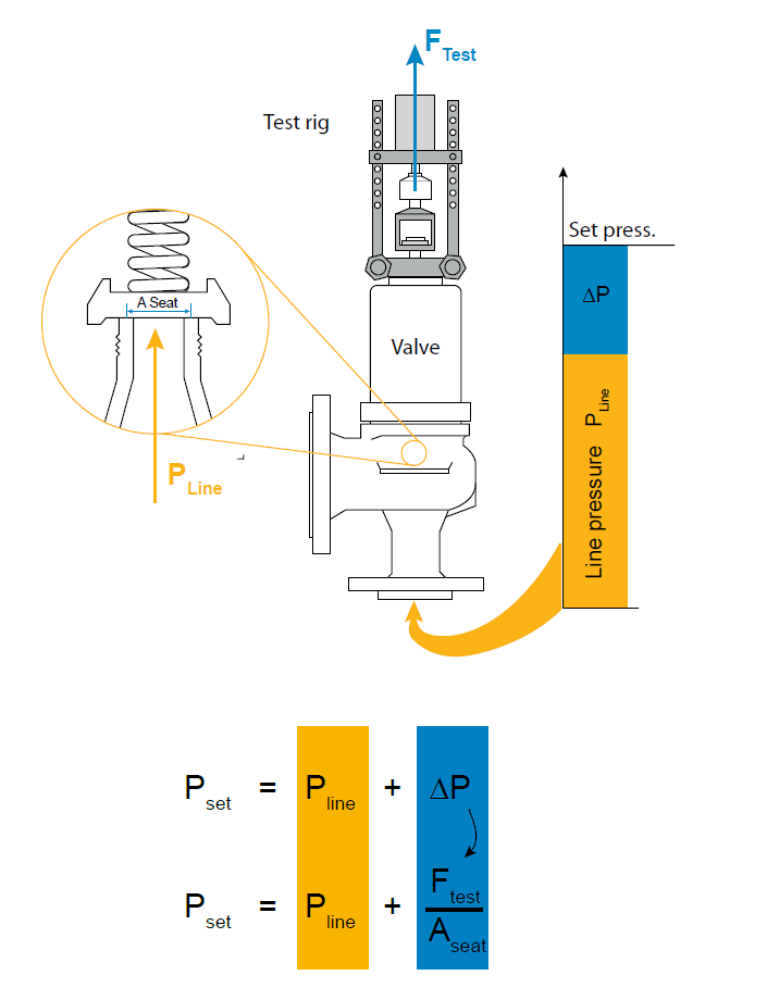
The Popping Test or Pop Test is a set pressure test of Pressure Relief Valve (PRV). It is done by compressing air into the inlet of PRV until the valve opens. Engineers then compare the opening force with the set pressure of the PRV to see whether the valve functions as specified.
When pressure surpasses the safety threshold, relief valves pop off. The “popping off” action expels surplus pressure until the tank’s pressure drops to the designated minimum pressure. The valve then resets and closes automatically after completing the blowdown procedure.
Safety is imperative and test technicians should always behave as if the valve under pressure will physically implode at any moment. ASME Section I Division VIII covers testing criteria for pressure vessel and boiler applications. Other codes such as API may apply depending on the application.
Before testing, determine the set pressure of the PRV. Properly manufactured and serviced PRVs have a set pressure engraved on a tag that’s riveted onto the body. Ensure the gauge you’re using has the proper measuring range for the pressure you’ve set.
Reduce the pressure gradually and record the reseating pressure (the pressure at which the valve closes). This happens instantly if the pressure source contains too low of a volume, thus making the seating pressure too hard to record.
Even though the fundamental PRV testing technique is relatively straightforward, it produces results based on simple observation with minimal backing data. Provision of signed certifications allows for little to no traceability other than the technician’s word.
Always stay within the test stand’s pressure limits and ensure the test stand erects correctly. Ensure the valve’s escaping pressure directs away from the operator and that everyone in the test area wears safety shields and eye protection.
With this in mind, the application of pressure Relief Valves should be assigned only to fully trained personnel and strictly comply with rules provided by the governing codes and standards.
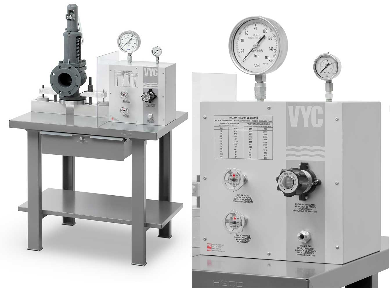
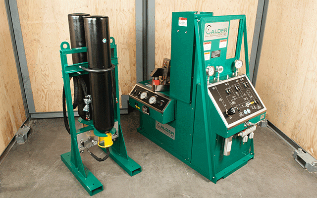
Bench testing provides the most popular type of pressure relief valve testing because it allows for work to occur in a controlled shop environment. Testing of valves that have already been in service, requires shutdown of the process system. Then, a lab takes receipt of the valve, checks it, and prepares it for testing.
An accurate pressure relief valve testing approach that does not need valve removal or facility downtime is inline testing. A competent technician can test valves in the system using inline safety relief valve testing equipment to determine the actual setpoint. Any testing that does not require bench testing may be a suitable candidate for inline pressure relief valve testing. It does away with the downtime requirement and delivers highly accurate results.
While not a popping test, all pressure relief valves require regular manual testing. An operated-in-place test occurs by manually activating the test lever on the valve. This ensures the valve can open and close tightly, but it does not validate its opening and closing pressure. This test requires quarterly or bi-annually to ensure the most basic functionality of safety relief valves.
The accumulation test is a boiler safety test that determines whether the safety valves can release steam quickly enough to keep the pressure rising by 10%. The main steam stop valve closes during this safety valve accumulation test. With the burner on, it validates that the steam pressure will not climb over 10% prior to the safety valve releasing excess steam pressure to the atmosphere.
Hydro testing, more formally called hydrostatic testing, is performed on pressure vessels to check for leaks. This testing completely fills a pressure vessel with water and pressures it. Once pressurized, leaks can be detected. Testing occurs in accordance with ASME Section VIII Division I.

When it comes to understanding pressure relief valve testing requirements, there’s a lot of information out there, but not all of it seems conclusive. If you’re new to pressure relief valves or are getting started in a new industry, it can be tough to decipher what testing requirements your facility needs to meet.
While we can’t provide the specific testing requirements for every industry, we can offer a few general testing requirements, and point you in the right direction to find the information you need for your facility’s unique testing requirements:
It’s good to keep in mind that every industry and region has unique pressure relief valve testing requirements. Your facility may be required to just bench test pressure relief valves every five years, or you may have to test valves every year, but bench test and repair valves every three to five years. There is a large variance in the testing requirements for pressure relief and safety valves depending on your industry and your region. That said, there are a few general testing requirements we can look at to start with.
The National Board Inspection Code, created by the National Board of Boiler and Pressure Valve Inspectors, makes the following recommendations on the frequency of testing for safety and pressure relief valves, depending on the temperature, psi, and function of your boiler:
High-pressure steam boilers greater than 15 psi and less than 400 psi should be manually checked every 6 months and pressure tested annually to verify nameplate set pressure.
High-pressure steam boilers greater than 400 psi should be pressure tested to verify nameplate set pressure every three years, or as determined by operating experience as verified by testing history.
High-temperature hot water boilers operating at greater than 160 psi and/or 250° F should be pressure tested annually to verify nameplate set pressure.
It’s important to remember that these are general pressure valve testing recommendations. For specific requirements, you’ll have to verify your unique jurisdictional and industry code requirements. See the resources below for more information.
The National Board Inspection Code is an industry-recognized name offering quality information on pressure relief valve testing requirements. Here, you’ll find a wealth of information and testing best practices.
The ASME is another organization setting pressure relief valve testing requirements, and offering the necessary training engineers need to test and understand the testing procedures for pressure relief valves. In addition to testing requirements and standards, the ASME offers a variety of online courses on pressure relief valves, from fabrication and proper installation to inspection and repair.
For specific testing standards, it’s best to check with your industry and your regional jurisdiction. Pressure relief valve testing requirements can vary by state or region and are most often industry-specific. Check your industry’s standards, and check local code requirements to ensure your facility is adhering to the most relevant pressure relief valve testing requirements.
When you’re looking for the pressure relief valve testing requirements relevant to your facility, it’s important to understand the different testing methods that are available to you. It’s likely that regardless of your industry if you have safety and pressure relief valves in use at your facility, you’ll have to bench test those valves at least every five years.
In addition to those bench tests, though, you’ll also have to perform manual or on-site pressure relief valve testing. Here’s a quick look at the three most common pressure relief valve testing methods you’ll see when researching pressure relief valve testing requirements:
The most commonly mandated form of pressure relief valve testing, bench testing is unique in that it requires you completely shut down your facility’s system and remove all pressure relief valves. The valves are then transported to a lab where they are tested and repaired as necessary. Tested valves are then re-installed in your system.
Bench testing is the most involved method of pressure relief valve testing, but as this is how valves are tested when they’re manufactured, the industry considers this to be the most thorough testing method.
Inline testing is another accurate pressure relief valve testing method that doesn’t require the removal of valves or facility downtime. With inline safety relief valve testing equipment, a trained technician can test valves in the system to calculate the real setpoint of a valve in the system.
While inline testing cannot take the place of mandated bench testing, it is a more efficient form of testing for other regular testing requirements. Inline pressure relief valve testing is the ideal choice for any required testing that does not have to be bench testing, as it eliminates the need for downtime while still providing exceptionally accurate results.
Some pressure relief valve testing requirements will call for regular manual testing for freedom of operation. This is a basic test that can be done on-site. To complete an operated-in-place test, the test lever on the valve is manually activated. This test functions to ensure that the valve can open and shut tightly, but it does not verify at what pressure the valve opens and shuts. This is a test that may be required quarterly or bi-annually, to ensure the most basic functionality of safety relief valves.
Pressure relief valve testing is necessary for any facility with safety relief and pressure relief valves. For more information about the equipment you need for pressure relief valve testing, the profitability of certain testing methods, and more, head to the AccuTEST blog. There, you’ll find a variety of resources on everything from implementing inline safety relief valve testing to minimizing plant downtime.
If your company requires regular pressure relief valve testing, you might be interested in AccuTEST’s high-tech equipment. Offering inline testing with accurate, repeatable results, our system is the best on the market. See how our equipment works in real-time — schedule a live webinar demo today.


 8613371530291