
boiler safety valve testing procedure price
Tired of keeping track of your valve inventory’s annual certification records? We offer complete management of your safety relief valves. With an inventory of repair parts and in stock relief valves of all sizes, we can respond to any customer emergency. We offer annual certification services as well as repair of all major brands, including Kunkle, Conbraco, Consolidated, Dresser, Apollo and more.

LegaTest on-line testing for safety valves system is designed and integrated with proven software and the highest specification of equipment to guarantee equipment integrity and ensuring compliance with statutory requirements.
Legatest opens the valve slightly by pulling the spindle. Force, pressure, lift and sound sensors are sending signals to electronic data acquisition control unit and PC. LCD is showing 4 curves:
This service was developed to help customers avoid loss of productivity and improve operational uptime. Data acquisition software allows the system to keep full records of all your safety valves. Test results are stored on the database for future maintenance requirements. Full test results and certification are presented to comply with your statutory requirements and support further diagnostics as required.
"We are offering our service online safety valve testing in Qatar, Saudi Arabia, Bahrain, United Arab Emirates, Oman, Kuwait, Asia, Europe and all middle east countries".
On-line welded safety valves can be tested in the In-Situ position without cutting,Welding,Removing and Outage of the plant,which give considerable at time saving and cost saving to the customer enormously.
Safety valve can be tested when plant/boiler is in operating condition (Hot test) without increasing the pressure of the boiler also the valve can be tested in during shutdown (Cold test) on both condition that test can be performed.
Around ₹50,000 to ₹75,000 per safety valve cost saving will be effected to the customer in comparision with conventional test methods and other test. The cost saving is benficial to the customer in our lega test(Advanced LegaTest)Online safety valve testing system

For many years, ultrasound has been utilised by various vendors as an additional method to find the set point in cases the standard diagrams are hard to analyse. This can be the case when testing safety valves on liquid services.
Within an extensive benchmark test, METRUS in co operation with Sweden‘s biggest nuclear power station Ringhals AB investigated the approach to use ultrasound as an additional indication for the set point on liquid service safety valves. The result of 55 tests on different valves is that the „Ultrasound point“ is completely depending on the seat condition. This result perfectly first the fact that ultrasound will detect the start to leak point and not the set point (start to lift point).
Only on a new or freshly serviced valve, the set point will be close to the ultrasound point. Even tiniest soiling or improper maintenance will cause the ultrasound to severely „drift away“ from the true set point. Within a typical online safety valve testing scenario where a valve has not bee serviced for a year or more, it is not at all recommended to use ultrasound to identify the set point.
There are still two useful applications for ultrasound within online safety valve testing. A very simple but effective use is to compare the sound level of the valve before and after the test. Comparing those sound levels will indicate if after the test (disk lift) the valve is left in a similar condition to its previous untested state. This could be first information if the valve did properly reseat and seal after it has been lifted. White Paper – Online safety valve testing METRUS Valve Test Bench Exellence
Knowing why safety valves should be tested online and how this is done in theory, it is most helpful to get an idea of the every day questions you will have to deal with. It will enable you to imagine how online safety valve testing appears in real life.
Plant operators are often surprised when being asked by online testing engineers whether it is a problem to open a valve. Considering the definition of the set point to be the initial moment when the disk starts to lift the safety valve disk must lift to find that point in a test diagram. It very much depends on the test equipment how long and high the valve will open, but it definitely has to open. geöffnet wird.
To test a safety valve, it must be possible to lift the disk and measure the force when doing so. If a safety valve has a spindle, it is possible in 95% of all cases to test it online. Some valves might require a simple spindle modification. This depends on the valve and the adapter solution how to „connect“ the test rig. Valves that do not have a spindle at all can not be tested.
Valves installed on extremely dirty fluids like bituminous crude oil should not be tested unless they are equipped with a rupture disk to keep the seat clean. Dirt could prevent the disk from sealing properly and the valve will remain leaking after the test. It the maintenance departments decision whether to agree with slightly lifting a valve or not.
Safety valves installed in EEx areas require special equipment to operate the test rig. If such equipment is available, it is important to check the specific EEx certificate for the approved EEx class and EEx area. As of now and to our best knowledge, there is no online safety valve testing system available that has an EEx approval for the whole machine. The test rigs are approved but the power unit usually has to stay outside the EEx area or have to be protected with special temporary solutions.
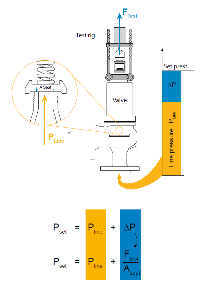
A frequent question to be found in industry is „what is the highest set point and the largest nominal diameter you can test?“. According to the online testing formula of fig. 1 the set pressure is calculated from line pressure, seat area and test force. Those parameters interact. The more line pressure is to be found under the safety vales disk the less force is required to lift (test) it. A final statement can never be made as it depends on seat area, set point and line pressure, whether or not the force capacity of specific equipment will be strong enough to test a valve.
Some suppliers claim that their equipment can test „any“ safety valve. Technically speaking it means raising the line pressure will lead to a remaining test force small enough to be covered by the test equipments force capacity. As online safety valve testing should not affect the plant operation this statement is not very respectable. Usually the line pressure can not be changed significantly just to test a valve.
Thinking about the largest valves, small and medium valves are often forgotten. But those ½“ and 1“ valves built the majority of valves to be found in industry. It is a technical fact, that each measurement task requires suitable sensor ranges. Large valves require large forces and small valves usually small forces. The operational range of online safety valve test equipment is therefore not only defined by its strongest force capacity. It is a question how accurate it can deal with a variety of forces and pressures – small and large.
Online safety valve testing offers major cost saving potential. In most cases it is cheaper than workshop testing after comparing direct testing costs. This of course requires the test equipment to be efficient in handling and operation.
Safety valves need to be tested at various locations within a plant. It is common to move the test equipment a few times during a test day. Different valve types to be tested require retooling of the test rig. In every day life the equipment will be packed and unpacked several times and it will require adaptation to fit the test rig on the safety valve. Valves will be located on top of tall reactors and on difficult to reach places under or behind pipelines.
The test equipments performance is significantly defined by its mechanical performance – weight and flexibility. The time for unpacking and rigging up as well as for wiring all sensors etc. determines, how fast the individual valve test will be. And in many cases the safety valve requires adjustment. Depending on how long it takes to take the rig off the safety valve, testing and re-testing will be fast and efficient or time consuming.
Within a typical online safety valve test scenario, a valve might need to be adjusted. To adjust a valve, it requires to remove the rig (RR) adjust the valve (VA) and reinstall (RI) the rig before you can carry out the next test to see, if the adjustment was successful. This is done usually two times until a satisfying set pressure is adjusted.
The relation between handling and testing time in average test equipment is about 1/5. It becomes obvious that total test time and efficiency are significantly depending on the test rig performance – weight, portability and speed of set up / dismantling.
It may happen that safety valves stay open after the test. To make sure that such event does not affect the plant operation, a concept to remotely close the safety valve, using the test rig is absolutely necessary for safe online safety valve testing.
Testing safety valves online is not at all dangerous as long as the procedure is done properly and the system performs as it should. But there are rare scenarios in which a plant disturbance could appear, especially if a safety valve stays open or gets damaged.
Online safety valve test equipment today is either manually or electronically controlled. Electronic systems support the test process and monitor test limits, taking a lot of responsibility from the technician. TESON® e.g. automatically drives the complete lifting process, monitoring all sensor signals for pre calculated test limits. But electronic systems are sensitive to power black outs as well as to software malfunctions. To deal professionally with those, the online safety valve testing system must have an extensive safety system to guarantee the safety valve will never be blocked open or damaged – whatever might happen.
Manually controlled system are not sensitive to power black outs or system failures. They leave the full control over the test process to the technician. It is up to the technician to control the lifting force and whether or not to overload a valve. Especially with manually controlled system experience plays an important role as the safety issue is basically the human factor. Despite that even manually driven system must have some safety features to respond to hardware or hydraulic malfunction.
Considering the number of parameters to be considered and monitored during an online safety valve test, digital systems are definitely superior as the chance of malfunction and power black outs is considerably small if the systems are well designed and extensively tested. Even after intensive training and years experience it is barely possible for a technician to compete with the reliability and response time of a digital system. Considering the background of online safety valve testing it is a derived requirement of the system to be safely and correctly operated with minimum skill and experience.
When thinking of a first time investment, it is very often the purchase price that plays an important role. But if you consider the cost saving potential of online safety valve testing or the profit you could make with a service, it becomes obvious that there is more to be considered to get a real view on the cost of ownership.
Support from your supplier will be crucial for your business. If you are facing time sensitive testing sessions and your equipment gets damaged or you come across complex questions, delays of operations or loosing your customer to the competition can cause severe loss of profit. The system vendor should be able to minimize downtimes with an intelligent support strategy. This includes 24 h availability of technical support, access to most spare parts in local markets and availability of rental equipment to substitute yours during service and repair. The more a supplier is focused on the online safety valve testing business, the better resources he will offer to support your every day work.
Like all measuring equipment, online safety valve testing systems require calibration. Sensors and measuring electronic need calibration (typically every 2-3 years) to harmonize with ISO quality standards. Suppliers must be able to either offer you a calibration service or advice you where to get such service. To minimize transportation costs, the parts and modules that need calibration should be easy to isolate for shipping.
The variety of valves to be found in industry is huge. It is not at all practical to own every type of special equipment that might be required one day to test special applications. Your investment will be significantly lower if you can own core components that cover the majority of your every day online testing needs. Your supplier should offer you special extension for rent to cover the remaining applications once they are required.
We hope this white paper could draw a picture what online safety valve testing is about. If you have any further related question, please feel free to contact METRUS at any time. It will be our pleasure to support and consult you..

The National Board offers the Certificate of Authorization and VR Stamp for the repair of pressure relief valves. Requirements are included in the current mandatory edition of the National Board Inspection Code(NBIC), Part 4, and NB-514, Accreditation of VR Repair Organizations.
The National Board offers the Certificate of Authorization for use of the T/O mark which indicates accreditation as a pressure relief valve Testing Organization. The program includes provisions for minor adjustments to restore valve performance. Requirements are based upon the current mandatory edition of the National Board Inspection Code(NBIC), Part 2, Part 4, and NB-528, Accreditation of T/O Test Only Organizations.
The National Board supports members who request tests be conducted on pressure relief devices involved in boiler and pressure vessel accidents. This service is provided at no cost to the National Board member. Please contact Pressure Relief or Executive staff for more information.
Representatives from the National Board are assigned to visit company sites to select production sample valves for testing at National Board- and ASME- accepted labs.
Pressure safety valves are designed to protect process piping and equipment in case of an overpressure event. TEAM Valve Solutions inspects, tests, repairs and re-certifies safety valves at 17 service centers across three continents, and in our fleet of mobile facilities, all of which are audited under the jurisdiction of relevant governing bodies.
Our solutions cover all major safety valve brands and support our customers through an inventory of spare parts and loose-assembled valves. In addition, our facilities are audited and governed by the National Board of Boiler and Pressure Vessel Inspectors. Testing, repair, and assembly are performed under license and guidelines of NBIC, and ASME Section I and VIII.
To ensure accurate in-line setpoint verification, TEAM Valve Solutions utilizes Trevitest, the pioneering system for validating safety valve performance in Conventional and Nuclear Power plants, as well as in other industrial process facilities.

Trevi test is use for set pressure of safety valve with online while safety valve in service without adding pressure in whole system approaching the set pressure. Trevi test kit use the Hydraulic lift assist device to help pull spindle of safety valve to overcome spring force without increasing pressure in a system.
In early time in power plant we were not using trevi test for checking the pressure of safety valve instate of that we increase the pressure of system till the safety valve will not pop up than by comparing the control room valve pressure data we can set the pressure by tightening or loose the adjusting screw. But this method can be risky as well as time consuming and it can be reason of generation lose in the power plant.
Ask Running line pressure to operation department and enter that pressure in software, Calculate the pulled force from above formula then enter it in software then operate pressure applying switch that plot the graph in software the first deflection in the graph indicates the operate value of safety valve if this value is more then set value than we open lock nut of safety valve then tight adjusting screw if the value is less then set value than we open lock nut of safety valve then lose adjusting screw then tight lock nut, then take second trial to set the setting pressure.
In order to ensure that the maximum allowable accumulation pressure of any system or apparatus protected by a safety valve is never exceeded, careful consideration of the safety valve’s position in the system has to be made. As there is such a wide range of applications, there is no absolute rule as to where the valve should be positioned and therefore, every application needs to be treated separately.
A common steam application for a safety valve is to protect process equipment supplied from a pressure reducing station. Two possible arrangements are shown in Figure 9.3.3.
The safety valve can be fitted within the pressure reducing station itself, that is, before the downstream stop valve, as in Figure 9.3.3 (a), or further downstream, nearer the apparatus as in Figure 9.3.3 (b). Fitting the safety valve before the downstream stop valve has the following advantages:
• The safety valve can be tested in-line by shutting down the downstream stop valve without the chance of downstream apparatus being over pressurised, should the safety valve fail under test.
• When setting the PRV under no-load conditions, the operation of the safety valve can be observed, as this condition is most likely to cause ‘simmer’. If this should occur, the PRV pressure can be adjusted to below the safety valve reseat pressure.
Indeed, a separate safety valve may have to be fitted on the inlet to each downstream piece of apparatus, when the PRV supplies several such pieces of apparatus.
• If supplying one piece of apparatus, which has a MAWP pressure less than the PRV supply pressure, the apparatus must be fitted with a safety valve, preferably close-coupled to its steam inlet connection.
• If a PRV is supplying more than one apparatus and the MAWP of any item is less than the PRV supply pressure, either the PRV station must be fitted with a safety valve set at the lowest possible MAWP of the connected apparatus, or each item of affected apparatus must be fitted with a safety valve.
• The safety valve must be located so that the pressure cannot accumulate in the apparatus viaanother route, for example, from a separate steam line or a bypass line.
It could be argued that every installation deserves special consideration when it comes to safety, but the following applications and situations are a little unusual and worth considering:
• Fire - Any pressure vessel should be protected from overpressure in the event of fire. Although a safety valve mounted for operational protection may also offer protection under fire conditions,such cases require special consideration, which is beyond the scope of this text.
• Exothermic applications - These must be fitted with a safety valve close-coupled to the apparatus steam inlet or the body direct. No alternative applies.
• Safety valves used as warning devices - Sometimes, safety valves are fitted to systems as warning devices. They are not required to relieve fault loads but to warn of pressures increasing above normal working pressures for operational reasons only. In these instances, safety valves are set at the warning pressure and only need to be of minimum size. If there is any danger of systems fitted with such a safety valve exceeding their maximum allowable working pressure, they must be protected by additional safety valves in the usual way.
In order to illustrate the importance of the positioning of a safety valve, consider an automatic pump trap (see Block 14) used to remove condensate from a heating vessel. The automatic pump trap (APT), incorporates a mechanical type pump, which uses the motive force of steam to pump the condensate through the return system. The position of the safety valve will depend on the MAWP of the APT and its required motive inlet pressure.
This arrangement is suitable if the pump-trap motive pressure is less than 1.6 bar g (safety valve set pressure of 2 bar g less 0.3 bar blowdown and a 0.1 bar shut-off margin). Since the MAWP of both the APT and the vessel are greater than the safety valve set pressure, a single safety valve would provide suitable protection for the system.
Here, two separate PRV stations are used each with its own safety valve. If the APT internals failed and steam at 4 bar g passed through the APT and into the vessel, safety valve ‘A’ would relieve this pressure and protect the vessel. Safety valve ‘B’ would not lift as the pressure in the APT is still acceptable and below its set pressure.
It should be noted that safety valve ‘A’ is positioned on the downstream side of the temperature control valve; this is done for both safety and operational reasons:
Operation - There is less chance of safety valve ‘A’ simmering during operation in this position,as the pressure is typically lower after the control valve than before it.
Also, note that if the MAWP of the pump-trap were greater than the pressure upstream of PRV ‘A’, it would be permissible to omit safety valve ‘B’ from the system, but safety valve ‘A’ must be sized to take into account the total fault flow through PRV ‘B’ as well as through PRV ‘A’.
A pharmaceutical factory has twelve jacketed pans on the same production floor, all rated with the same MAWP. Where would the safety valve be positioned?
One solution would be to install a safety valve on the inlet to each pan (Figure 9.3.6). In this instance, each safety valve would have to be sized to pass the entire load, in case the PRV failed open whilst the other eleven pans were shut down.
If additional apparatus with a lower MAWP than the pans (for example, a shell and tube heat exchanger) were to be included in the system, it would be necessary to fit an additional safety valve. This safety valve would be set to an appropriate lower set pressure and sized to pass the fault flow through the temperature control valve (see Figure 9.3.8).

There is a wide range of safety valves available to meet the many different applications and performance criteria demanded by different industries. Furthermore, national standards define many varying types of safety valve.
The ASME standard I and ASME standard VIII for boiler and pressure vessel applications and the ASME/ANSI PTC 25.3 standard for safety valves and relief valves provide the following definition. These standards set performance characteristics as well as defining the different types of safety valves that are used:
ASME I valve - A safety relief valve conforming to the requirements of Section I of the ASME pressure vessel code for boiler applications which will open within 3% overpressure and close within 4%. It will usually feature two blowdown rings, and is identified by a National Board ‘V’ stamp.
ASME VIII valve- A safety relief valve conforming to the requirements of Section VIII of the ASME pressure vessel code for pressure vessel applications which will open within 10% overpressure and close within 7%. Identified by a National Board ‘UV’ stamp.
Full bore safety valve - A safety valve having no protrusions in the bore, and wherein the valve lifts to an extent sufficient for the minimum area at any section, at or below the seat, to become the controlling orifice.
Conventional safety relief valve -The spring housing is vented to the discharge side, hence operational characteristics are directly affected by changes in the backpressure to the valve.
Balanced safety relief valve -A balanced valve incorporates a means of minimising the effect of backpressure on the operational characteristics of the valve.
Pilot operated pressure relief valve -The major relieving device is combined with, and is controlled by, a self-actuated auxiliary pressure relief device.
Power-actuated safety relief valve - A pressure relief valve in which the major pressure relieving device is combined with, and controlled by, a device requiring an external source of energy.
Standard safety valve - A valve which, following opening, reaches the degree of lift necessary for the mass flowrate to be discharged within a pressure rise of not more than 10%. (The valve is characterised by a pop type action and is sometimes known as high lift).
Full lift (Vollhub) safety valve -A safety valve which, after commencement of lift, opens rapidly within a 5% pressure rise up to the full lift as limited by the design. The amount of lift up to the rapid opening (proportional range) shall not be more than 20%.
Direct loaded safety valve -A safety valve in which the opening force underneath the valve disc is opposed by a closing force such as a spring or a weight.
Proportional safety valve - A safety valve which opens more or less steadily in relation to the increase in pressure. Sudden opening within a 10% lift range will not occur without pressure increase. Following opening within a pressure of not more than 10%, these safety valves achieve the lift necessary for the mass flow to be discharged.
Diaphragm safety valve -A direct loaded safety valve wherein linear moving and rotating elements and springs are protected against the effects of the fluid by a diaphragm
Bellows safety valve - A direct loaded safety valve wherein sliding and (partially or fully) rotating elements and springs are protected against the effects of the fluids by a bellows. The bellows may be of such a design that it compensates for influences of backpressure.
Controlled safety valve - Consists of a main valve and a control device. It also includes direct acting safety valves with supplementary loading in which, until the set pressure is reached, an additional force increases the closing force.
Safety valve - A safety valve which automatically, without the assistance of any energy other than that of the fluid concerned, discharges a quantity of the fluid so as to prevent a predetermined safe pressure being exceeded, and which is designed to re-close and prevent further flow of fluid after normal pressure conditions of service have been restored. Note; the valve can be characterised either by pop action (rapid opening) or by opening in proportion (not necessarily linear) to the increase in pressure over the set pressure.
Direct loaded safety valve -A safety valve in which the loading due to the fluid pressure underneath the valve disc is opposed only by a direct mechanical loading device such as a weight, lever and weight, or a spring.
Assisted safety valve -A safety valve which by means of a powered assistance mechanism, may additionally be lifted at a pressure lower than the set pressure and will, even in the event of a failure of the assistance mechanism, comply with all the requirements for safety valves given in the standard.
Supplementary loaded safety valve - A safety valve that has, until the pressure at the inlet to the safety valve reaches the set pressure, an additional force, which increases the sealing force.
Note; this additional force (supplementary load), which may be provided by means of an extraneous power source, is reliably released when the pressure at the inlet of the safety valve reaches the set pressure. The amount of supplementary loading is so arranged that if such supplementary loading is not released, the safety valve will attain its certified discharge capacity at a pressure not greater than 1.1 times the maximum allowable pressure of the equipment to be protected.
Pilot operated safety valve -A safety valve, the operation of which is initiated and controlled by the fluid discharged from a pilot valve, which is itself, a direct loaded safety valve subject to the requirement of the standard.
The common characteristic shared between the definitions of conventional safety valves in the different standards, is that their operational characteristics are affected by any backpressure in the discharge system. It is important to note that the total backpressure is generated from two components; superimposed backpressure and the built-up backpressure:
Subsequently, in a conventional safety valve, only the superimposed backpressure will affect the opening characteristic and set value, but the combined backpressure will alter the blowdown characteristic and re-seat value.
The ASME/ANSI standard makes the further classification that conventional valves have a spring housing that is vented to the discharge side of the valve. If the spring housing is vented to the atmosphere, any superimposed backpressure will still affect the operational characteristics. Thiscan be seen from Figure 9.2.1, which shows schematic diagrams of valves whose spring housings are vented to the discharge side of the valve and to the atmosphere.
By considering the forces acting on the disc (with area AD), it can be seen that the required opening force (equivalent to the product of inlet pressure (PV) and the nozzle area (AN)) is the sum of the spring force (FS) and the force due to the backpressure (PB) acting on the top and bottom of the disc. In the case of a spring housing vented to the discharge side of the valve (an ASME conventional safety relief valve, see Figure 9.2.1 (a)), the required opening force is:
In both cases, if a significant superimposed backpressure exists, its effects on the set pressure need to be considered when designing a safety valve system.
Once the valve starts to open, the effects of built-up backpressure also have to be taken into account. For a conventional safety valve with the spring housing vented to the discharge side of the valve, see Figure 9.2.1 (a), the effect of built-up backpressure can be determined by considering Equation 9.2.1 and by noting that once the valve starts to open, the inlet pressure is the sum of the set pressure, PS, and the overpressure, PO.
Balanced safety valves are those that incorporate a means of eliminating the effects of backpressure. There are two basic designs that can be used to achieve this:
Although there are several variations of the piston valve, they generally consist of a piston type disc whose movement is constrained by a vented guide. The area of the top face of the piston, AP, and the nozzle seat area, AN, are designed to be equal. This means that the effective area of both the top and bottom surfaces of the disc exposed to the backpressure are equal, and therefore any additional forces are balanced. In addition, the spring bonnet is vented such that the top face of the piston is subjected to atmospheric pressure, as shown in Figure 9.2.2.
The bellows arrangement prevents backpressure acting on the upper side of the disc within the area of the bellows. The disc area extending beyond the bellows and the opposing disc area are equal, and so the forces acting on the disc are balanced, and the backpressure has little effect on the valve opening pressure.
Bellows failure is an important concern when using a bellows balanced safety valve, as this may affect the set pressure and capacity of the valve. It is important, therefore, that there is some mechanism for detecting any uncharacteristic fluid flow through the bellows vents. In addition, some bellows balanced safety valves include an auxiliary piston that is used to overcome the effects of backpressure in the case of bellows failure. This type of safety valve is usually only used on critical applications in the oil and petrochemical industries.
Since balanced pressure relief valves are typically more expensive than their unbalanced counterparts, they are commonly only used where high pressure manifolds are unavoidable, or in critical applications where a very precise set pressure or blowdown is required.
This type of safety valve uses the flowing medium itself, through a pilot valve, to apply the closing force on the safety valve disc. The pilot valve is itself a small safety valve.
The diaphragm type is typically only available for low pressure applications and it produces a proportional type action, characteristic of relief valves used in liquid systems. They are therefore of little use in steam systems, consequently, they will not be considered in this text.
The piston type valve consists of a main valve, which uses a piston shaped closing device (or obturator), and an external pilot valve. Figure 9.2.4 shows a diagram of a typical piston type, pilot operated safety valve.
The piston and seating arrangement incorporated in the main valve is designed so that the bottom area of the piston, exposed to the inlet fluid, is less than the area of the top of the piston. As both ends of the piston are exposed to the fluid at the same pressure, this means that under normal system operating conditions, the closing force, resulting from the larger top area, is greater than the inlet force. The resultant downward force therefore holds the piston firmly on its seat.
If the inlet pressure were to rise, the net closing force on the piston also increases, ensuring that a tight shut-off is continually maintained. However, when the inlet pressure reaches the set pressure, the pilot valve will pop open to release the fluid pressure above the piston. With much less fluid pressure acting on the upper surface of the piston, the inlet pressure generates a net upwards force and the piston will leave its seat. This causes the main valve to pop open, allowing the process fluid to be discharged.
When the inlet pressure has been sufficiently reduced, the pilot valve will reclose, preventing the further release of fluid from the top of the piston, thereby re-establishing the net downward force, and causing the piston to reseat.
Pilot operated safety valves offer good overpressure and blowdown performance (a blowdown of 2% is attainable). For this reason, they are used where a narrow margin is required between the set pressure and the system operating pressure. Pilot operated valves are also available in much larger sizes, making them the preferred type of safety valve for larger capacities.
One of the main concerns with pilot operated safety valves is that the small bore, pilot connecting pipes are susceptible to blockage by foreign matter, or due to the collection of condensate in these pipes. This can lead to the failure of the valve, either in the open or closed position, depending on where the blockage occurs.
The terms full lift, high lift and low lift refer to the amount of travel the disc undergoes as it moves from its closed position to the position required to produce the certified discharge capacity, and how this affects the discharge capacity of the valve.
A full lift safety valve is one in which the disc lifts sufficiently, so that the curtain area no longer influences the discharge area. The discharge area, and therefore the capacity of the valve are subsequently determined by the bore area. This occurs when the disc lifts a distance of at least a quarter of the bore diameter. A full lift conventional safety valve is often the best choice for general steam applications.
The disc of a high lift safety valve lifts a distance of at least 1/12th of the bore diameter. This means that the curtain area, and ultimately the position of the disc, determines the discharge area. The discharge capacities of high lift valves tend to be significantly lower than those of full lift valves, and for a given discharge capacity, it is usually possible to select a full lift valve that has a nominal size several times smaller than a corresponding high lift valve, which usually incurs cost advantages.Furthermore, high lift valves tend to be used on compressible fluids where their action is more proportional.
In low lift valves, the disc only lifts a distance of 1/24th of the bore diameter. The discharge area is determined entirely by the position of the disc, and since the disc only lifts a small amount, the capacities tend to be much lower than those of full or high lift valves.
Except when safety valves are discharging, the only parts that are wetted by the process fluid are the inlet tract (nozzle) and the disc. Since safety valves operate infrequently under normal conditions, all other components can be manufactured from standard materials for most applications. There are however several exceptions, in which case, special materials have to be used, these include:
Cast steel -Commonly used on higher pressure valves (up to 40 bar g). Process type valves are usually made from a cast steel body with an austenitic full nozzle type construction.
For all safety valves, it is important that moving parts, particularly the spindle and guides are made from materials that will not easily degrade or corrode. As seats and discs are constantly in contact with the process fluid, they must be able to resist the effects of erosion and corrosion.
The spring is a critical element of the safety valve and must provide reliable performance within the required parameters. Standard safety valves will typically use carbon steel for moderate temperatures. Tungsten steel is used for higher temperature, non-corrosive applications, and stainless steel is used for corrosive or clean steam duty. For sour gas and high temperature applications, often special materials such as monel, hastelloy and ‘inconel’ are used.
Standard safety valves are generally fitted with an easing lever, which enables the valve to be lifted manually in order to ensure that it is operational at pressures in excess of 75% of set pressure. This is usually done as part of routine safety checks, or during maintenance to prevent seizing. The fitting of a lever is usually a requirement of national standards and insurance companies for steam and hot water applications. For example, the ASME Boiler and Pressure Vessel Code states that pressure relief valves must be fitted with a lever if they are to be used on air, water over 60°C, and steam.
A test gag (Figure 9.2.7) may be used to prevent the valve from opening at the set pressure during hydraulic testing when commissioning a system. Once tested, the gag screw is removed and replaced with a short blanking plug before the valve is placed in service.
The amount of fluid depends on the particular design of safety valve. If emission of this fluid into the atmosphere is acceptable, the spring housing may be vented to the atmosphere – an open bonnet. This is usually advantageous when the safety valve is used on high temperature fluids or for boiler applications as, otherwise, high temperatures can relax the spring, altering the set pressure of the valve. However, using an open bonnet exposes the valve spring and internals to environmental conditions, which can lead to damage and corrosion of the spring.
When the fluid must be completely contained by the safety valve (and the discharge system), it is necessary to use a closed bonnet, which is not vented to the atmosphere. This type of spring enclosure is almost universally used for small screwed valves and, it is becoming increasingly common on many valve ranges since, particularly on steam, discharge of the fluid could be hazardous to personnel.
Some safety valves, most commonly those used for water applications, incorporate a flexible diaphragm or bellows to isolate the safety valve spring and upper chamber from the process fluid, (see Figure 9.2.9).

Riggio Valve Services technology enables safe and economical in-place safety relief valve testing during normal operations with no operational interruption. Yearly re-certification may be achieved without the need for valve removal provided specific prerequisites and qualifications meet code requirements. Test procedures, measurements and analysis facilitate:
Riggio is authorized by the National Board of Boiler and Pressure Vessel Inspectors. The procedure is recognized by ASME and can be found in Interpretations I-83-31 and VIII –1-83-350. It is also covered in ASME Section I PG-72.2
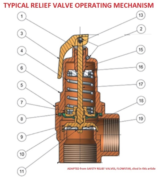
Relief valves are designed to open at a preset pressure (or temperature) level and relieve the system when it has exceeded the desired level. The valve"s relief of elevated liquid, gas, or steam pressures prevents damage to the system. We offer a wide selection of relief valves for any application.


 8613371530291