
boiler steam safety valve free sample

In order to ensure that the maximum allowable accumulation pressure of any system or apparatus protected by a safety valve is never exceeded, careful consideration of the safety valve’s position in the system has to be made. As there is such a wide range of applications, there is no absolute rule as to where the valve should be positioned and therefore, every application needs to be treated separately.
A common steam application for a safety valve is to protect process equipment supplied from a pressure reducing station. Two possible arrangements are shown in Figure 9.3.3.
The safety valve can be fitted within the pressure reducing station itself, that is, before the downstream stop valve, as in Figure 9.3.3 (a), or further downstream, nearer the apparatus as in Figure 9.3.3 (b). Fitting the safety valve before the downstream stop valve has the following advantages:
• The safety valve can be tested in-line by shutting down the downstream stop valve without the chance of downstream apparatus being over pressurised, should the safety valve fail under test.
• When setting the PRV under no-load conditions, the operation of the safety valve can be observed, as this condition is most likely to cause ‘simmer’. If this should occur, the PRV pressure can be adjusted to below the safety valve reseat pressure.
Indeed, a separate safety valve may have to be fitted on the inlet to each downstream piece of apparatus, when the PRV supplies several such pieces of apparatus.
• If supplying one piece of apparatus, which has a MAWP pressure less than the PRV supply pressure, the apparatus must be fitted with a safety valve, preferably close-coupled to its steam inlet connection.
• If a PRV is supplying more than one apparatus and the MAWP of any item is less than the PRV supply pressure, either the PRV station must be fitted with a safety valve set at the lowest possible MAWP of the connected apparatus, or each item of affected apparatus must be fitted with a safety valve.
• The safety valve must be located so that the pressure cannot accumulate in the apparatus viaanother route, for example, from a separate steam line or a bypass line.
It could be argued that every installation deserves special consideration when it comes to safety, but the following applications and situations are a little unusual and worth considering:
• Fire - Any pressure vessel should be protected from overpressure in the event of fire. Although a safety valve mounted for operational protection may also offer protection under fire conditions,such cases require special consideration, which is beyond the scope of this text.
• Exothermic applications - These must be fitted with a safety valve close-coupled to the apparatus steam inlet or the body direct. No alternative applies.
• Safety valves used as warning devices - Sometimes, safety valves are fitted to systems as warning devices. They are not required to relieve fault loads but to warn of pressures increasing above normal working pressures for operational reasons only. In these instances, safety valves are set at the warning pressure and only need to be of minimum size. If there is any danger of systems fitted with such a safety valve exceeding their maximum allowable working pressure, they must be protected by additional safety valves in the usual way.
In order to illustrate the importance of the positioning of a safety valve, consider an automatic pump trap (see Block 14) used to remove condensate from a heating vessel. The automatic pump trap (APT), incorporates a mechanical type pump, which uses the motive force of steam to pump the condensate through the return system. The position of the safety valve will depend on the MAWP of the APT and its required motive inlet pressure.
This arrangement is suitable if the pump-trap motive pressure is less than 1.6 bar g (safety valve set pressure of 2 bar g less 0.3 bar blowdown and a 0.1 bar shut-off margin). Since the MAWP of both the APT and the vessel are greater than the safety valve set pressure, a single safety valve would provide suitable protection for the system.
Here, two separate PRV stations are used each with its own safety valve. If the APT internals failed and steam at 4 bar g passed through the APT and into the vessel, safety valve ‘A’ would relieve this pressure and protect the vessel. Safety valve ‘B’ would not lift as the pressure in the APT is still acceptable and below its set pressure.
It should be noted that safety valve ‘A’ is positioned on the downstream side of the temperature control valve; this is done for both safety and operational reasons:
Operation - There is less chance of safety valve ‘A’ simmering during operation in this position,as the pressure is typically lower after the control valve than before it.
Also, note that if the MAWP of the pump-trap were greater than the pressure upstream of PRV ‘A’, it would be permissible to omit safety valve ‘B’ from the system, but safety valve ‘A’ must be sized to take into account the total fault flow through PRV ‘B’ as well as through PRV ‘A’.
A pharmaceutical factory has twelve jacketed pans on the same production floor, all rated with the same MAWP. Where would the safety valve be positioned?
One solution would be to install a safety valve on the inlet to each pan (Figure 9.3.6). In this instance, each safety valve would have to be sized to pass the entire load, in case the PRV failed open whilst the other eleven pans were shut down.
If additional apparatus with a lower MAWP than the pans (for example, a shell and tube heat exchanger) were to be included in the system, it would be necessary to fit an additional safety valve. This safety valve would be set to an appropriate lower set pressure and sized to pass the fault flow through the temperature control valve (see Figure 9.3.8).
My name is Kelly Paffel, Technical Manager for Inveno Engineering, LLC, located in Tampa, Florida. We are an engineering firm focused on steam and condensate systems. Today I want to talk about steam safety valves: sizing, selection, installation, best practices. Steam safety valves installed wherever the maximum allowable working steam pressure of a system or over pressurizing a containing vessel is likely to be exceeded. In particular under fault conditions due to a failure of another piece of equipment in the system.
The typical system we have a pressure inducing valve here. We have a pressure 200 PSI here. And our equipment down here is only rated for 150 PSI, then we need to protect it with a safety relief valve. And typically, that safety relief valve will be set for the lowest rated equipment or component in the system; pressure and temperature rating.
The codes for this steam safety valve is governed by the American Society of Mechanical Engineers (ASME). ASME, through its committees, has established Boiler and Pressure Vessel Codes for safety though rules and formulas indicating a good practice. The National Board of Boiler and Pressure Vessel Inspectors has the authority to verify, administer and enforce this ASME code wherever it has been adopted. Therefore any safety valve that we must follow the code set out by ASME and under the jurisdiction of the national report.
Steam safety valve codes. In the steam system, we look at section one which is for the boilers or power boilers. Section 4 is for heating boilers and section 8 is for pressure vessels out there away from the boiler in the steam system. So, anything away from the boiler, we’re typically looking at section 8, safety valves. The example shows right here, this picture here shows the safety valve located on the boiler, which is going to be section 1.
The code stamps and it’s meaning, we have A, M, N, PP, S, U, U2, UV, and V. So these are the codes and these are the meanings of the code. For example, PP is pressure piping, S is for power boilers, U is for pressure vessels, and V is for boiler safety valves.
We’re going to discuss sizing and selection of a safety valve. We’re looking at the design type. The design type can be the standard safety valve, which is shown here, or we can use pilot operated. Then we have body drains, a lifting device here. Some people prefer to have a lifting device, some people do not prefer. Of course the materials here have to be rated for the max pressure and temperature of the system. So that depends on the material, so if we get in to the higher pressures, when we’re dealing with super heat, then materials have to be selected for that super heat pressure and temperature.
The sealing adjustments typically is adjustments here for the over pressurization in blow down, and the set point tolerance has got to be come up with on safety valves. Now, we’re now getting into the details on the internals of the safety valve and we’re going to talk about the selection process.
So here’s a typical application, we’re going to do this for pressure reduction. So we’re reducing steam pressure here, downstream here. Our equipment downstream, we have a device that only rated for 100PSI, 338 degrees. So we’re going to have to put in a safety valve here. So we’re reducing the pressure here to 50PSI for our operation, but we have to protect the system which is going to be 100PSI chain.
Now, the thing is that we typically have a 10 percent differential between the operating set pressures recommended, and the thing is that this pressure differential would be, if we’re operating at 100PSI, or our safety valve is set for 100PSI and we want to operate at 90PSI or lower. That’s due to, the safety valve can go into, what we call simmer[inaudible 00:05:27] so we want to be at least 10 percent away from our set pressure of our safety valve for the operating pressure of the system. Now, some people recommend 20 percent, and that gets into the lower pressure operation where we’re reducing pressures down to 10 or 12 PSI and we have our safety valve set there for 5PSI. So if my system safety valve is set for 15PSI, it would operate the system at 10PSI to stay away from that simmer effect of the safety valve and that’s per code that the safety valve can go into simmer.
The total capacity of a safety valve at set pressure must exceed the control valve or pressure-reducing valve’s maximum capacity, if the valve were to fail in a fully open position. So if this valve were to fail in the fully open position, this safety valve has to be able to discharge the total capacity. Now, total capacity of the boilers, is the maximum BTU fuel input on the boiler. So the safety valve must be able to relieve the maximum steam output with the maximum BTU input to that boiler, depending on the type of fuel that you’re using for that boiler. Multiple safety valve installation is possible if the capacity can not be reached with one safety valve. It’s common to find that with boilers that we have two or three safety valves to get to the capacity that’s required for that operation.
The steam safety valves sizing designation is designated by numbers. Excuse me. Letters. So up here you’ll see the letters, here. K, L, M, N, P. That gives us the effective orifice area. So if I have a set pressure here 100 PSI, and a P orifice, we have this capacity here, which is around 37012 pounds per hour. So we look up the safety valve and see 4 by 6 P. P means the orifice inside the safety valve.
Now, a safety relief valve must be mounted in the vertical position. The reason mounted in the vertical position is a safety valve is set up as assembled or manufactured in the vertical position, so you must duplicate how the position is of the safety valve. The system must be free of dirt of course. Upstream piping connection must be at least equal to the valve, so if the end of the valve is 6 inches, then this connection valve here needs to be 6 inches.
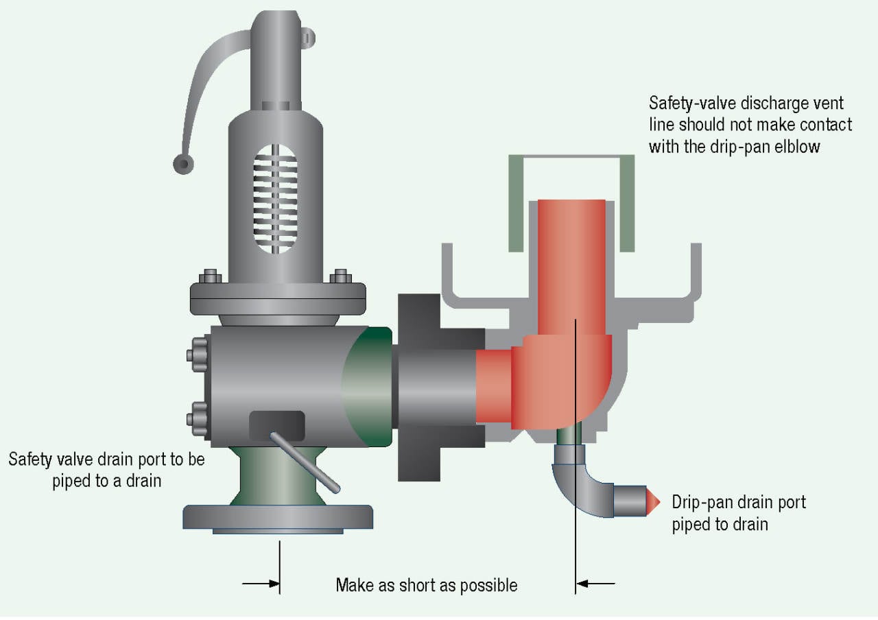
With the steam safety valve no shutoff valve can be installed down here, and do not plug the drain valves, and the discharge lines should be no less than the full area of the valve. In the [inaudible 00:08:38] that make sure we have a drip pan elbow put onto the valve, and this just changes direction from horizontal to vertical, and increases the pipe on pipe diameter, and then the vent pipe can come down but does not make contact with the drip pan elbow. The outlet always must discharge where no one can be at harm’s way, typically to the top of the building or the unit, and cut it at a 45 degree angle to signify it’s a steam safety valve. So you cut it at a 45 degree angle, it used to be 7 feet, and this has recently changed, it’s now 10 feet above. That’s a typical installation of a safety valve.
We also have best practices up on the website, to go into more detail on safety valves, but this is just a short version to give you some idea. So if we can be of service, here is out contact information, and have a great day.

Boiler explosions have been responsible for widespread damage to companies throughout the years, and that’s why today’s boilers are equipped with safety valves and/or relief valves. Boiler safety valves are designed to prevent excess pressure, which is usually responsible for those devastating explosions. That said, to ensure that boiler safety valves are working properly and providing adequate protection, they must meet regulatory specifications and require ongoing maintenance and periodic testing. Without these precautions, malfunctioning safety valves may fail, resulting in potentially disastrous consequences.
Boiler safety valves are activated by upstream pressure. If the pressure exceeds a defined threshold, the valve activates and automatically releases pressure. Typically used for gas or vapor service, boiler safety valves pop fully open once a pressure threshold is reached and remain open until the boiler pressure reaches a pre-defined, safe lower pressure.
Boiler relief valves serve the same purpose – automatically lowering boiler pressure – but they function a bit differently than safety valves. A relief valve doesn’t open fully when pressure exceeds a defined threshold; instead, it opens gradually when the pressure threshold is exceeded and closes gradually until the lower, safe threshold is reached. Boiler relief valves are typically used for liquid service.
There are also devices known as “safety relief valves” which have the characteristics of both types discussed above. Safety relief valves can be used for either liquid or gas or vapor service.
Nameplates must be fastened securely and permanently to the safety valve and remain readable throughout the lifespan of the valve, so durability is key.
The National Board of Boiler and Pressure Vessel Inspectors offers guidance and recommendations on boiler and pressure vessel safety rules and regulations. However, most individual states set forth their own rules and regulations, and while they may be similar across states, it’s important to ensure that your boiler safety valves meet all state and local regulatory requirements.
The National Board published NB-131, Recommended Boiler and Pressure Vessel Safety Legislation, and NB-132, Recommended Administrative Boiler and Pressure Vessel Safety Rules and Regulationsin order to provide guidance and encourage the development of crucial safety laws in jurisdictions that currently have no laws in place for the “proper construction, installation, inspection, operation, maintenance, alterations, and repairs” necessary to protect workers and the public from dangerous boiler and pressure vessel explosions that may occur without these safeguards in place.
The American Society of Mechanical Engineers (ASME) governs the code that establishes guidelines and requirements for safety valves. Note that it’s up to plant personnel to familiarize themselves with the requirements and understand which parts of the code apply to specific parts of the plant’s steam systems.
High steam capacity requirements, physical or economic constraints may make the use of a single safety valve impossible. In these cases, using multiple safety valves on the same system is considered an acceptable practice, provided that proper sizing and installation requirements are met – including an appropriately sized vent pipe that accounts for the total steam venting capacity of all valves when open at the same time.
The lowest rating (MAWP or maximum allowable working pressure) should always be used among all safety devices within a system, including boilers, pressure vessels, and equipment piping systems, to determine the safety valve set pressure.
Avoid isolating safety valves from the system, such as by installing intervening shut-off valves located between the steam component or system and the inlet.
Contact the valve supplier immediately for any safety valve with a broken wire seal, as this indicates that the valve is unsafe for use. Safety valves are sealed and certified in order to prevent tampering that can prevent proper function.
Avoid attaching vent discharge piping directly to a safety valve, which may place unnecessary weight and additional stress on the valve, altering the set pressure.
A boiler valve kit is a must-have for any homeowner with a boiler system. This brass valve kit features a vent safety valve that helps to protect your home from dangerous gas build-up. The included instructions make installation easy, and the durable brass construction ensures lasting performance. Keep your family safe with this essential boiler valve kit.
9. When the calibrated pressure is reached, the valve opens automatically and discharges the atmosphere to protect the whole system from safe caused by overpressure
10. This brass boiler valve kit is perfect for any steam-powered project. The kit includes a pressure gauge, safety valve, and two shut-off valves. The pressure gauge helps you monitor the pressure in your boiler, the safety valve keeps your boiler from exploding, and the shut-off valves let you turn off the steam supply without having to drain the boiler.
This brass boiler valve kit is perfect for any steam-related projects you may have. It includes a durable boiler and vent safety valve to keep your project safe and functional. The included instructions make it easy to install this kit in no time. This boiler valve kit is the perfect addition to your tool collection with its high-quality construction and affordable price. This brass boiler valve kit is ideal for any steam-based appliance. The kit includes a boiler valve, vent safety valve, and all the necessary fittings for a quick and easy installation. The included vent safety valve helps to ensure safe operation by releasing excess pressure in the event of a malfunction. This kit is ideal for use with any boiler, including cast iron, steel, or copper boilers.
Vent safety valves are required for all direct-fired appliances; this kit includes everything you need to install one. The boiler valve is brass and has a 1/2-inch pipe thread fitting that can be connected to the vent pipe. It also features an adjustable pressure relief valve with a gauge, protecting your home from high-pressure steam or air from the system. This kit comes with two elbows (1 in., two in.), four nipples (3/4 in., 1/8 in., 3/8 in.), three straight fittings (5/16 inches), and five pipe connectors (3 ways).
This boiler kit includes a brass pressure relief valve with an air vent, which is required by law. It also has a 1/2″ discharge elbow and two unions connecting the pipe inlet to your water heater. The safety valves are designed to prevent excess pressure from building up inside the tank, which can cause dangerous boil-overs or even potential explosions. This kit is excellent for homeowners with existing water heaters without this equipment installed.
Steam and hot water boilers shall be equipped, respectively, with listed or approved steam safety or pressure-relief valves of appropriate discharge capacity and conforming with ASME requirements. A shutoff valve shall not be placed between the relief valve and the boiler or on discharge pipes between such valves and the atmosphere. [NFPA 54:10.3.6]

Stainless Steel Safety Relief Valve is a safety mechanism deployed in applications to prevent them from bursting under pressure. Suraj Metal Corporationis a leading manufacturer and supplier of the different types such as the Brass Safety Valveand others in various sizes and dimensions. The valves are fitted with the pipelines in a way that when the pressure goes above the threshold level, the Stainless Steel Air Safety Valveopens up and relieves the system of pressure.
This is important to prevent the pipes from being damaged or bursting under high pressure. The Stainless Steel Safety Exhaust Ball Valveis used in the exhaust systems where the temperature plays major role. When the temperature exceeds certain point, it increases pressure and the safety valve opens and balances the pressure in the system. The spring loaded boiler safety valveis used in boilers and heat exchanger systems where steam and hot water are circulated through pipes. There are different gas safety valvetypes and each of these differ in their purpose and functions. Please feel free to contact us for more information on the different types of air compressor pressure relief valveand others with pricing.
We Keep Bulk Stock of CF8 stainless steel Pressure Safety Valve at our stockyard, contact us for Free Sample & stock list, View Brass Safety Valve Dimension chart
find Stainless Steel Safety Exhaust Ball Valve Dimensions, price list, size chart here, Buy ASTM A351 CF8M 316 temperature safety valve at best price in India

The primary purpose of a safety valve is to protect life, property and the environment. Safety valves are designed to open and release excess pressure from vessels or equipment and then close again.
The function of safety valves differs depending on the load or main type of the valve. The main types of safety valves are spring-loaded, weight-loaded and controlled safety valves.
Regardless of the type or load, safety valves are set to a specific set pressure at which the medium is discharged in a controlled manner, thus preventing overpressure of the equipment. In dependence of several parameters such as the contained medium, the set pressure is individual for each safety application.

A little product education can make you look super smart to customers, which usually means more orders for everything you sell. Here’s a few things to keep in mind about safety valves, so your customers will think you’re a genius.
A safety valve is required on anything that has pressure on it. It can be a boiler (high- or low-pressure), a compressor, heat exchanger, economizer, any pressure vessel, deaerator tank, sterilizer, after a reducing valve, etc.
There are four main types of safety valves: conventional, bellows, pilot-operated, and temperature and pressure. For this column, we will deal with conventional valves.
A safety valve is a simple but delicate device. It’s just two pieces of metal squeezed together by a spring. It is passive because it just sits there waiting for system pressure to rise. If everything else in the system works correctly, then the safety valve will never go off.
A safety valve is NOT 100% tight up to the set pressure. This is VERY important. A safety valve functions a little like a tea kettle. As the temperature rises in the kettle, it starts to hiss and spit when the water is almost at a boil. A safety valve functions the same way but with pressure not temperature. The set pressure must be at least 10% above the operating pressure or 5 psig, whichever is greater. So, if a system is operating at 25 psig, then the minimum set pressure of the safety valve would be 30 psig.
Most valve manufacturers prefer a 10 psig differential just so the customer has fewer problems. If a valve is positioned after a reducing valve, find out the max pressure that the equipment downstream can handle. If it can handle 40 psig, then set the valve at 40. If the customer is operating at 100 psig, then 110 would be the minimum. If the max pressure in this case is 150, then set it at 150. The equipment is still protected and they won’t have as many problems with the safety valve.
Here’s another reason the safety valve is set higher than the operating pressure: When it relieves, it needs room to shut off. This is called BLOWDOWN. In a steam and air valve there is at least one if not two adjusting rings to help control blowdown. They are adjusted to shut the valve off when the pressure subsides to 6% below the set pressure. There are variations to 6% but for our purposes it is good enough. So, if you operate a boiler at 100 psig and you set the safety valve at 105, it will probably leak. But if it didn’t, the blowdown would be set at 99, and the valve would never shut off because the operating pressure would be greater than the blowdown.
All safety valves that are on steam or air are required by code to have a test lever. It can be a plain open lever or a completely enclosed packed lever.
Safety valves are sized by flow rate not by pipe size. If a customer wants a 12″ safety valve, ask them the flow rate and the pressure setting. It will probably turn out that they need an 8×10 instead of a 12×16. Safety valves are not like gate valves. If you have a 12″ line, you put in a 12″ gate valve. If safety valves are sized too large, they will not function correctly. They will chatter and beat themselves to death.
Safety valves need to be selected for the worst possible scenario. If you are sizing a pressure reducing station that has 150 psig steam being reduced to 10 psig, you need a safety valve that is rated for 150 psig even though it is set at 15. You can’t put a 15 psig low-pressure boiler valve after the reducing valve because the body of the valve must to be able to handle the 150 psig of steam in case the reducing valve fails.
The seating surface in a safety valve is surprisingly small. In a 3×4 valve, the seating surface is 1/8″ wide and 5″ around. All it takes is one pop with a piece of debris going through and it can leak. Here’s an example: Folgers had a plant in downtown Kansas City that had a 6×8 DISCONTINUED Consolidated 1411Q set at 15 psig. The valve was probably 70 years old. We repaired it, but it leaked when plant maintenance put it back on. It was after a reducing valve, and I asked him if he played with the reducing valve and brought the pressure up to pop the safety valve. He said no, but I didn’t believe him. I told him the valve didn’t leak when it left our shop and to send it back.
If there is a problem with a safety valve, 99% of the time it is not the safety valve or the company that set it. There may be other reasons that the pressure is rising in the system before the safety valve. Some ethanol plants have a problem on starting up their boilers. The valves are set at 150 and they operate at 120 but at startup the pressure gets away from them and there is a spike, which creates enough pressure to cause a leak until things get under control.
If your customer is complaining that the valve is leaking, ask questions before a replacement is sent out. What is the operating pressure below the safety valve? If it is too close to the set pressure then they have to lower their operating pressure or raise the set pressure on the safety valve.
Is the valve installed in a vertical position? If it is on a 45-degree angle, horizontal, or upside down then it needs to be corrected. I have heard of two valves that were upside down in my 47 years. One was on a steam tractor and the other one was on a high-pressure compressor station in the New Mexico desert. He bought a 1/4″ valve set at 5,000 psig. On the outlet side, he left the end cap in the outlet and put a pin hole in it so he could hear if it was leaking or not. He hit the switch and when it got up to 3,500 psig the end cap came flying out like a missile past his nose. I told him to turn that sucker in the right direction and he shouldn’t have any problems. I never heard from him so I guess it worked.
If the set pressure is correct, and the valve is vertical, ask if the outlet piping is supported by something other than the safety valve. If they don’t have pipe hangers or a wall or something to keep the stress off the safety valve, it will leak.
There was a plant in Springfield, Mo. that couldn’t start up because a 2″ valve was leaking on a tank. It was set at 750 psig, and the factory replaced it 5 times. We are not going to replace any valves until certain questions are answered. I was called to solve the problem. The operating pressure was 450 so that wasn’t the problem. It was in a vertical position so we moved on to the piping. You could tell the guy was on his cell phone when I asked if there was any piping on the outlet. He said while looking at the installation that he had a 2″ line coming out into a 2×3 connection going up a story into a 3×4 connection and going up another story. I asked him if there was any support for this mess, and he hung up the phone. He didn’t say thank you, goodbye, or send me a Christmas present.

(f) When operating conditions are changed, or additional boiler heating surface is installed, the valve capacity shall be increased, if necessary, to meet the new conditions and be in accordance with HG-400.l (e). The additional valves required, on account of changed conditions, may be installed on the outlet piping provided there is no intervening valve.
(a) Each hot water heating or supply boiler shall have at least one officially rated safety relief valve, of the automatic reseating type, identified with the V or HV Symbol, and set to relieve at or below the maximum allowable working pressure of the boiler.
(b) Hot water heating or supply boilers limited to a water temperature not in excess of 210°F (99°C) may have, in lieu of the valve(s) specified in (a) above, one or more officially rated temperature and pressure safety relief valves of the automatic reseating type identified with the HV symbol, and set to relieve at or below the maximum allowable working pressure of the boiler.
(c) When more than one safety relief valve is used on either hot water heating or hot water supply boilers, the additional valves shall be officially rated and may have a set pressure within a range not to exceed 6 psi (40 kPa) above the maximum allowable working pressure of the boiler up to and including 60 psi (400 kPa), and 5% for those having a maximum allowable working pressure exceeding 60 psi (400 kPa).
(d) No safety relief valve shall be smaller than NPS ¾ (DN 20) nor larger than NPS 4 (DN 100) except that boilers having a heat input not greater than 15,000 Btu/hr (4.4 kW) may be equipped with a rated safety relief valve of NPS ½ (DN 15).
(e) The required steam relieving capacity, in pounds per hour (kg/h), of the pressure relieving device or devices on a boiler shall be the greater of that determined by dividing the maximum output in Btu at the boiler nozzle obtained by the firing of any fuel for which the unit is installed by 1,000, or shall be determined on the basis of pounds (kg) of steam generated per hour per square foot (m2) of boiler heating surface as given in Table HG-400.1. For cast iron boilers constructed to the requirements of Part HC, the minimum valve capacity shall be determined by the maximum output method. In many cases a greater relieving capacity of valves will have to be provided than the minimum specified by these rules. In every case, the requirements of HG-400.2 (g) shall be met.
(f) When operating conditions are changed, or additional boiler heating surface is installed, the valve capacity shall be increased, if necessary, to meet the new conditions and shall be in accordance with HG-400,2(g). The additional valves required, on account of changed conditions, may be installed on the outlet piping provided there is no intervening valve.
(g) Safety relief valve capacity for each boiler with a single safety relief valve shall be such that, with the fuel burning equipment installed and operated at maximum capacity, the pressure cannot rise more than 10% above the maximum allowable working pressure. When more than one safety relief valve is used, the overpressure shall be limited to 10% above the set pressure of the highest set valve allowed by HG-400.2 (c).
(a)Steam to Hot Water Supply. When a hot water supply is heated indirectly by steam in a coil or pipe within the service limitations set forth in HG-101, the pressure of the steam used shall not exceed the safe working pressure of the hot water tank, and a safety relief valve at least NPS 1 (DN 25),set to relieve at or below the maximum allowable working pressure of the tank, shall be applied on the tank.
(b) High Temperature Water to Water Heat Exchanger.1 When high temperature water is circulated through the coils or tubes of a heat exchanger to warm water for space heating or hot water supply, within the service limitations set forth in HG-101, the heat exchanger shall be equipped with one or more officially rated safety relief valves that are identified with the V or HV Symbol, set to relieve at or below the maximum allowable working pressure of the heat exchanger, and of sufficient rated capacity to prevent the heat exchanger pressure from rising more than 10% above the maximum allowable working pressure of the vessel.
(c) High Temperature Water to Steam Heat Exchanger.1When high temperature water is circulated through the coils or tubes of a heat exchanger to generate low pressure steam, within the service limitations set forth in HG-101, the heat exchanger shall be equipped with one or more officially rated safety valves that are identified with the V or HV Symbol, set to relieve at a pressure not to exceed 15 psi (100 kPa), and of sufficient rated capacity to prevent the heat exchanger pressure from rising more than 5 psi (35 kPa) above the maximum allowable working pressure of the vessel. For heat exchangers requiring steam pressures greater than 15 psi (100 kPa), refer to Section I or Section VIII, Division 1.
(a) The inlet opening shall have an inside diameter approximately equal to, or greater than, the seat diameter. In no case shall the maximum opening through any part of the valve be less than ¼ in. (6 mm) in diameter or its equivalent area.
(c) O-rings or other packing devices when used on the stems of safety relief valves shall be so arranged as not to affect their operation or capacity.
(d) The design shall incorporate guiding arrangements necessary to insure consistent operation and tightness. Excessive lengths of guiding surfaces should be avoided. Bottom guided designs are not permitted on safety relief valves.
(f) Safety valves shall be spring loaded. The spring shall be designed so that the full lift spring compression shall be no greater than 80% of the nominal solid deflection. The permanent set of the spring (defined as the difference between the free height and height measured 10 min after the spring has been compressed solid three additional times after presetting at room temperature) shall not exceed 0.5% of the free height.
(g) There shall be a lifting device and a mechanical connection between the lifting device and the disk capable of lifting the disk from the seat a distance of at least 1/16 in. (1.5 mm) with no pressure on the boiler.
(h) A body drain below seat level shall be provided by the Manufacturer for all safety valves and safety relief valves, except that the body drain may be omitted when the valve seat is above the bottom of the inside diameter of the discharge piping. For valves exceeding NPS 2½ (DN 65) the drain hole or holes shall be tapped not less than NPS 3/8 (DN 10). For valves NPS 2½ (DN 65) or smaller, the drain hole shall not be less than ¼ in. (6 mm) in diameter. Body drain connections shall not be plugged during or after field installation. In safety relief valves of the diaphragm type, the space above the diaphragm shall be vented to prevent a buildup of pressure above the diaphragm. Safety relief valves of the diaphragm type shall be so designed that failure or deterioration of the diaphragm material will not impair the ability of the valve to relieve at the rated capacity.
(k) The set pressure tolerances, plus or minus, of safety valves shall not exceed 2 psi (15 kPa), and for safety relief valves shall not exceed 3 psi (20 kPa) for pressures up to and including 60 psig (400 kPa) and 5% for pressures above 60 psig (400 kPa).
(l) Safety valves shall be arranged so that they cannot be reset to relieve at a higher pressure than the maximum allowable working pressure of the boiler.
(e) Material for valve bodies and bonnets or their corresponding metallic pressure containing parts shall be listed in Section II,except that in cases where a manufacturer desires to make use of materials other than those listed in Section II, he shall establish and maintain specifications requiring equivalent control of chemical and physical properties and quality.
(g) No materials liable to fail due to deterioration or vulcanization when subjected to saturated steam temperature corresponding to capacity test pressure shall be used.
(a) A Manufacturer shall demonstrate to the satisfaction of an ASME designee that his manufacturing, production, and testing facilities and quality control procedures will insure close agreement between the performance of random production samples and the performance of those valves submitted for capacity certification.
(c) A Manufacturer may be granted permission to apply, the HV Code Symbol to production pressure relief valves capacity certified in accordance with HG-402.3 provided the following tests are successfully completed. This permission shall expire on the sixth anniversary of the date it is initially granted. The permission may be extended for 6 year periods if the following tests are successfully repeated within the 6 month period before expiration.
(1) Two sample production pressure relief valves of a size and capacity within the capability of an ASME accepted laboratory shall be selected by an ASME designee.
(2) Operational and capacity tests shall be conducted in the presence of an ASME designee at an ASME accepted laboratory. The valve Manufacturer shall be notified of the time of the test and may have representatives present to witness the test.
(3) Should any valve fail to relieve at or above its certified capacity or should it fail to meet performance requirements of this Section, the test shall be repeated at the rate of two replacement valves, selected in accordance with HG-401.3(c)(1), for each valve that failed.
(4) Failure of any of the replacement valves to meet the capacity or the performance requirements of this Section shall be cause for revocation within 60 days of the authorization to use the Code Symbol on that particular type of valve. During this period, the Manufacturer shall demonstrate the cause of such deficiency and the action taken to guard against future occurrence, and the requirements of HG-401.3(c) above shall apply.
(d) Safety valves shall be sealed in a manner to prevent the valve from being taken apart without breaking the seal. Safety relief valves shall be set and sealed so that they cannot be reset without breaking the seal.
(a) Every safety valve shall be tested to demonstrate its popping point, blowdown, and tightness. Every safety relief valve shall be tested to demonstrate its opening point and tightness. Safety valves shall be tested on steam or air and safety relief valves on water, steam, or air. When the blowdown is nonadjustable, the blowdown test may be performed on a sampling basis.
(c) Testing time on safety valves shall be sufficient, depending on size and design, to insure that test results are repeatable and representative of field performance.
HG-401.5 Design Requirements. At the time of the submission of valves for capacity certification, or testing in accordance with this Section, the ASME Designee has the authority to review the design for conformity with the requirements of this Section, and to reject or require modification of designs that do not conform, prior to capacity testing.
HG-402.1 Valve Markings. Each safety or safety-relief valve shall be plainly marked with the required data by the Manufacturer in such a way that the markings will not be obliterated in service. The markings shall be stamped, etched, impressed, or cast on the valve or on a nameplate, which shall be securely fastened to the valve.
(6) year built or, alternatively, a coding may be marked on the valves such that the valve Manufacturer can identify the year the valve was assembled and tested, and
HG-402.2 Authorization to Use ASME Stamp.Each safety valve to which the Code Symbol (Fig. HG-402) is to be applied shall be produced by a Manufacturer and/or Assembler who is in possession of a valid Certificate of Authorization. (See HG-540.) For all valves to be stamped with the HV Symbol, a Certified Individual (CI) shall provide oversight to ensure that the use of the “HV" Code symbol on a safety valve or safety relief valve is in accordance with this Section and that the use of the “HV" Code symbol is documented on a Certificate of Conformance Form, HV-1.
HG-402.3 Determination of Capacity to Be Stamped on Valves. The Manufacturer of the valves that are to be stamped with the Code symbol shall submit valves for testing to a place where adequate equipment and personnel are available to conduct pressure and relieving-capacity tests which shall be made in the presence of and certified by an authorized observer. The place, personnel, and authorized observer shall be approved by the Boiler and Pressure Vessel Committee. The valves shall be tested in one of the following three methods.
(a) Coefficient Method. Tests shall be made to determine the lift, popping, and blowdown pressures, and the capacity of at least three valves each of three representative sizes (a total of nine valves). Each valve of a given size shall be set at a different pressure. However, safety valves for steam boilers shall have all nine valves set at 15 psig (100 kPa). A coefficient shall be established for each test as follows:
A series of anomalies occurred in the boiler room that evening. The steel compression tank for the hydronic loop flooded, leaving no room for expansion. Water will expand at 3% of its volume when heated from room temperature to 180° F. When the burner fired, the expansion of the water increased the system pressure within the boiler. The malfunctioning operating control did not shut off the burner at the set point which caused the relief valve to open.
The brass relief valve discharge was installed with copper tubing piped solid to a 90° ell on the floor and the tubing further extended to the floor drain. The combination of hot water and steam from the boiler caused the discharge copper tubing to expand, using the relief valve as a fulcrum. The expansion of the copper discharge tubing pressing against the floor was enough to crack the brass relief valve, flooding the boiler room. The damage was not discovered until the next morning, several hours after the leak occurred. Thousands of dollars in damage was sustained and luckily no one was injured.
Each boiler requires some sort of pressure relieving device. They are referred to as either a safety, relief or safety relief valve. While these names are often thought of as interchangeable, there are subtle differences between them. According to the National Board of Boiler and Pressure Vessel Inspectors, the following are the definitions of each:
• Safety valve— This device is typically used for steam or vapor service. It operates automatically with a full-opening pop action and recloses when the pressure drops to a value consistent with the blowdown requirements prescribed by the applicable governing code or standard.
• Relief valve— This device is used for liquid service. It operates automatically by opening farther as the pressure increases beyond the initial opening pressure and recloses when the pressure drops below the opening pressure.
• Safety relief valve— This device includes the operating characteristics of both a safety valve and a relief valve and may be used in either application.
• Temperature and pressure safety relief valve— This device is typically used on potable water heaters. In addition to its pressure-relief function, it also includes a temperature-sensing element which causes the device to open at a predetermined temperature regardless of pressure. The set temperature on these devices is usually 210°.
• Relief valve piping— The boiler contractor installed a bushing on the outlet of the safety relief valve. Instead of 1 1/2-in. pipe, the installer used 3/4-in. pipe. When asked about it, he answered that he did not have any 1 1/2-in. pipe but had plenty of 3/4-in. pipe. I explained and then had to show the disbelieving contractor the code that states that the relief valve discharge piping has to be the same diameter as the relief valve outlet (see 2012 International Mechanical Code, 1006.6). By reducing the discharge pipe size, the relieving capacity of the safety valve may not be adequate to properly relieve the pressure inside the boiler, causing a dangerous situation.
The code also states that the discharge material shall be of rigid pipe that is approved for the temperature of the system. The inlet pipe size shall be full diameter of the pipe inlet for the relief valve. Some manufacturers suggest using black iron pipe rather than copper tubing. If using copper, it should have an air space that allows expansion should the relief valve open to avoid the accident that I referenced above. The discharge piping has to be supported and the weight of the piping should not be on the safety relief valve. Valves are not permitted in the inlet piping to or discharge piping from the relief valve. If you are using copper tubing on discharge piping, verify that there is room for expansion.
• Installation— Read the manufacturer’s installation manual as each may have different requirements. For instance, Conbraco requires that the discharge piping must terminate with a plain end and use a material that can handle temperatures of 375° or greater. This will preclude PVC or CPVC pipe for the discharge piping. The instruction manual for its model 12-14 steam relief valve stipulates that you cannot use a pipe wrench to install it. That would be good to know.
I once visited Boiler Utopia as the floor was clean and waxed. All the pipes were covered and exposed pipes were painted. There were large stickers detailing what was inside each pipe as well as directional arrows. Nothing was stacked next to the boilers. Yellow caution lines were painted on the floor around each boiler. I was in heaven. As I walked around the rear of the boiler, something clicked and triggered a warning bell. The discharge of the relief valve piping was about 6 in. from the floor but instead of a plain or angled cut end, the pipe had a threaded pipe cap on the termination. I asked the maintenance person about it and he said that the valve was leaking all over his newly waxed floor and this was the only way he could stop it. When I said that the discharge pipe should not have been threaded, he explained that it was not threaded and he had to take it to the local hardware store to thread it. I informed him that the cap had to be removed. We cut the pipe on an angle to prevent this.
• Steam boiler— Most manufacturers recommend a drip pan ell on the discharge of the steam boiler relief valve to eliminate the weight of the discharge piping on the relief valve. Some codes require the discharge to be vented outdoors.
• Testing— I will ask the attendees in my classes, “How often do you test the relief valves?” Most do not make eye contact and when I follow up with, “Why are they not tested?” I often hear that opening the relief valve will cause it to leak. I suggest that you refer to each manufacturer’s directions for testing. For instance, one will recommend once a year while another recommends twice a year. One manufacturer says, “Safety/relief valves should be operated only often enough to assure they are in good working order.” I am not sure what that even means. You want to also verify the proper test procedure as some will only want the relief valve tested when the boiler is at 75% of the rated pressure or higher of the relief valve.


 8613371530291