
consolidated 1811 safety valve free sample
A variety of pressure/temperature classes, orifice sizes and inlet/outlet combinations provide a flexible selection of safety valves to meet industrial needs at the lowest cost.
Low spindle bearing point and concentric spindle loading virtually eliminate the natural tendency for the disc to assume a horizontal position during the opening and closing cycle of the valve.
The mechanical flexibility of the Thermodisc allows the system pressure to assist in sealing the contact surface between the valve seat and Thermodisc.
Dual ring adjustments allow fine tuning of the safety valve performance characteristics needed to meet the steam system conditions that vary at each installation. A sharp, clean opening assures long valve seat life and reduced maintenance costs. Consistent opening and closing pressures contribute to efficient steam system operation.
SV-1 INDEX General Information Valve Selection .................................................................................................................GI.1 Features & Benefits ..........................................................................................................GI.3 How to Order ...................................................................................................................GI.16 Valve Coding ..................................................................................................................GI.20 Aftermarket Considerations .............................................................................................GI.27 1700 Scope of Design .......................................................................................................... 1700.1 Materials .......................................................................................................................1700.8 Dimension & Weights (USCS) ....................................................................................1700.19 Dimension & Weights (metric) ....................................................................................1700.25 Pressure / Temperature (USCS) ................................................................................1700.32 Pressure / Temperature (USCS) Alternate .................................................................1700.37 Orifice Capacities .......................................................................................................1700.42 Hydrostatic Test Plug ..................................................................................................1700.67 2700 Scope of Design ...........................................................................................................2700.1 Materials .......................................................................................................................2700.3 Dimension & Weights (USCS) ......................................................................................2700.5 Dimension & Weights (metric) ....................................................................................2700.11 Pressure / Temperature (USCS) ................................................................................2700.19 Pressure / Temperature (USCS) Alternate .................................................................2700.21 Orifice Capacities .......................................................................................................2700.23 Hydrostatic Test Plug ..................................................................................................2700.36 1811 Scope of Design ...........................................................................................................1811.1 Materials .......................................................................................................................1811.4 Dimension & Weights (USCS) ......................................................................................1811.5 Dimension & Weights (metric) ......................................................................................1811.7 Orifice Capacities .........................................................................................................1811.9 1511 Scope of Design ...........................................................................................................1511.1 Materials .......................................................................................................................1511.2 Dimension & Weights ...................................................................................................1511.3 Orifice Capacities .........................................................................................................1511.5
The CONSOLIDATED Pressure Relief Valve has been a leader in the industry since 1879, thus offering over a century of experience in design, engineering and product manufacture. CONSOLIDATED’S history of dependable and reliable valve service assures that today’s products and designs are consistent with the industry’s current requirements. Rigid manufacturing standards controlled by an ASME approved Quality Assurance Program and a certified/registered ISO 9001 Quality Assurance Program ensure that each valve will be manufactured in accordance with established design criteria and tested for functional performance. This quality-controlled manufacturing and test program assures that each valve manufactured will provide long and reliable service. CONSOLIDATED ASME Code Sections I and VIII Spring Loaded Pressure Relief Valves have been flow tested in accordance with the applicable ASME Code rules for the establishment of rated capacities and are listed in The National Board of Boiler and Pressure Vessel Inspectors publication Pressure Relieving Device Certifications.
Table of Contents Valve Selection . . . . . . . . . . . . . . . . . . . . . . . . . . . . . . . . . . . . . . . . . . . . . . . . . . . . . . . . . . . . . . . . . . . . . . .GI.1 Features & Benefits 1700 . . . . . . . . . . . . . . . . . . . . . . . . . . . . . . . . . . . . . . . . . . . . . . . . . . . . . . . . . . . . . . . . . . . . . . . . . . .GI.3 2700 . . . . . . . . . . . . . . . . . . . . . . . . . . . . . . . . . . . . . . . . . . . . . . . . . . . . . . . . . . . . . . . . . . . . . . . . . . .GI.7 1811 . . . . . . . . . . . . . . . . . . . . . . . . . . . . . . . . . . . . . . . . . . . . . . . . . . . . . . . . . . . . . . . . . . . . . . . . . . .GI.11 1511 . . . . . . . . . . . . . . . . . . . . . . . . . . . . . . . . . . . . . . . . . . . . . . . . . . . . . . . . . . . . . . . . . . . . . . . . . . .GI.13 1541/1543 . . . . . . . . . . . . . . . . . . . . . . . . . . . . . . . . . . . . . . . . . . . . . . . . . . . . . . . . . . . . . . . . . . . . . .GI.14 2478 . . . . . . . . . . . . . . . . . . . . . . . . . . . . . . . . . . . . . . . . . . . . . . . . . . . . . . . . . . . . . . . . . . . . . . . . . . .GI.15 How to Order . . . . . . . . . . . . . . . . . . . . . . . . . . . . . . . . . . . . . . . . . . . . . . . . . . . . . . . . . . . . . . . . . . . . . . . .GI.16 Valve Coding . . . . . . . . . . . . . . . . . . . . . . . . . . . . . . . . . . . . . . . . . . . . . . . . . . . . . . . . . . . . . . . . . . . . . . . . .GI.20 Aftermarket Considerations . . . . . . . . . . . . . . . . . . . . . . . . . . . . . . . . . . . . . . . . . . . . . . . . . . . . . . . . . . . . . .GI.27
1700 CONSOLIDATED Maxiflow® High Pressure Safety Valves are premium products that are installed in a majority of power generating stations worldwide to protect boilers from overpressure conditions. 1700
Our Green Tag® serves as a reminder that each CONSOLIDATED valve meets or exceeds the stringent performance and overpressure protection requirements set forth by the ASME and is backed by Dresser. Additionally, the symbol also represents our Green Tag Centers. These centers are fully certified by Dresser as CONSOLIDATED® valve assembly and repair facilities. They also meet or exceed the standards of the ASME and the National Board. Contact the authorized Green Tag Center in your local area to fill your immediate needs for CONSOLIDATED Pressure Relief Valves or call 1-800-245-VALV. Evidence of this quality is a Green Tag certification attached to the valve following final test and inspection.
1511 Valve type 1511 is a cast iron exposed spring safety valve. It is designed for ASME Code Sections I and VIII. This valve is specifically designed for steam generator and air service applications.
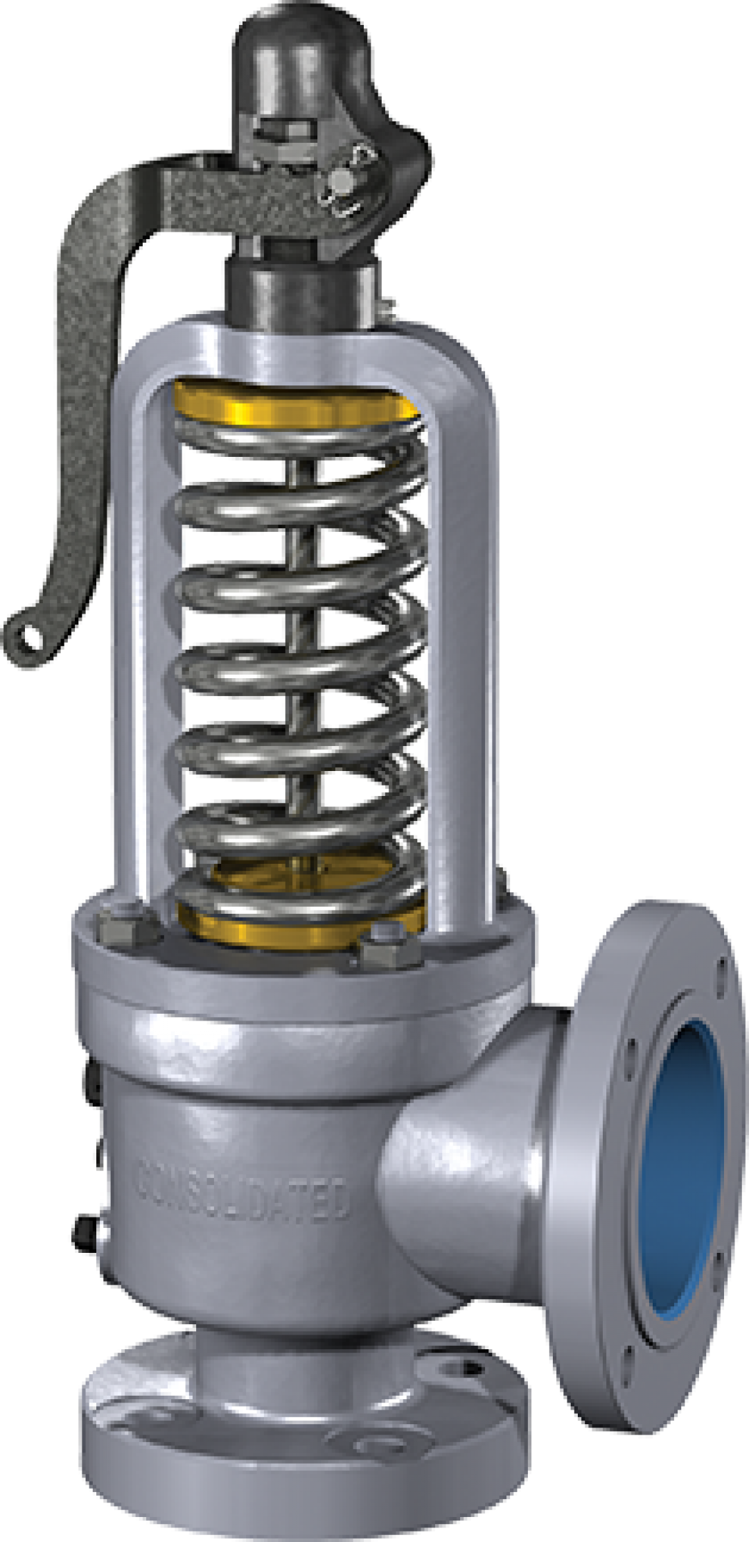
The 1811 safety valve is a high capacity flanged steel safety valve designed for steam service. The design is available in two pressure classes (300 and 600). Both pressure classes are provided with a ThermodiscTM seat design to assure maximum seat tightness. 1811
2478 Valve types 1541 and 1543 are ASME Code approved for Sections I and VIII. They are designed for steam and other compressible fluids. The valves should be used on compressible fluids only, not incompressible fluids such as water or oil. 1541/1543
3500 The Consolidated Series 3500 Electromatic Ball Valve is designed to provide automatic or manual overpressure protection for steam boiler systems, and can also be used to assist start-up and shutdown venting. 3500
Notes: 1. For maximum set pressure at a given temperature see the Pressure/Temperature chart for each valve type. 2. For set pressure less than 15 psig ASME code stamping is not allowed. 3. These valves have either an open yoke or a vented bonnet which should never be closed. 4. Do not exceed back pressure limits (% of Set Pressure) or the outlet flange rating (whichever is less). 5. ASME code approved products are permitted for use by the U.S. Coast Guard for marine applications which include power boilers, evaporators, heaters, and unfired pressure vessels. 6. The 2478 valve type is a closed bonnet design and can be used for hot liquids when closed discharge piping is used. This valve type is not recommended for vapor service. This valve is not ASME certified. 7. Back pressure not to exceed outlet flange rating.
CONSOLIDATED Maxiflow® high pressure safety valves are premium products that are installed on a majority of power generating stations worldwide to protect boilers from overpressure conditions.
When full lift is attained, (Figure 2), lift stop (M) rests against cover plate (P) to eliminate hunting, adding stability to the valve. When the valve discharges in an open position, steam is bled into chamber (H) through two bleed holes (J) in the roof of the disc holder. Similarly, the spindle overlap collar (K) rises to a fixed position above the floating washer (L). The area between the floating washer and the spindle is thereby increased by the difference in the two diameters on the overlap collar.
Under this condition, steam in chamber (H) enters into chamber (Q) through the secondary area formed by the floating washer (L) and the overlap collar (K) on the spindle, through orifice (N), and escapes to atmosphere through the pipe discharge connection (R). When closing, (Figure 3), the upper adjusting ring (G) initiates the pressure at which the valve will begin to close. The spindle overlap collar (K) is adjusted so that it moves down into the floating washer (L) thereby reducing the escape of steam from chamber (H) effectively. The resulting momentary pressure building up in chamber (H), at a rate controlled by orifice (N), produces a downward thrust in the direction of spring loading. The combined thrust of the pressure and spring loading results in positive and precise closing. Cushioning of the closing is controlled by the lower adjusting ring (O).
OVERLAP COLLAR — controls the pressure at which the valve will reseat. PRESSURE ASSISTED CLOSING — utilizes steam pressure to assist closing the valve and isolates the spring from steam pressure during actuation.
ADJUSTABLE LIFT STOP — matches safety valve capacity to boiler capacity, eliminates overpressure, protects against chatter, reduces reaction forces, assists stack sizing, and protects against over-compression of the spring.
UPPER ADJUSTING RING — for attaining full lift at pop and controlling the pressure at which the valve will begin to close. HIGH CAPACITY DISCHARGE — provides higher rated capacity and increases allowable backpressure to 25 percent of the valve’s set pressure.
THERMODISC — eliminates distortion due to thermal stresses. Temperature differentials quickly equalize and permanent tightness is ensured. LOWER ADJUSTING RING — ensures sharp pop action of the valve on opening and cushions the valve on closing. INLET CONNECTION — welded or flange.
Thermodisc Design The ThermodiscTM seat was designed and developed to address the problem of safety valve leakage. The disc design uses Inconel material and has an improved spindle pocket with concentric loading of the disc. These features, when combined with a low spindle bearing point and a thin flexible seat, provide a superior safety valve that has repeatable seat tightness.
Inconel material provides superior corrosive resistance and strength at high temperatures over a long period of time. The strength of the Inconel material prevents distortion in the spindle/disc contact area during actuation. A more durable disc material helps to maintain the safety valves original set pressure despite numerous actuations and further improves the longevity of the safety valve.
Projected Spring Force Concentric Disc Loading Concentric disc loading equalizes the spring force being transmitted to the valve seating area. The disc remains concentric to the centerline of the valve nozzle and ensures that the valve will reseat in its original seating position. The effective seating area remains constant, producing repeatable valve opening pressures.
Low Spindle Bearing Point A low spindle bearing point locates the point of spring force transmission below the horizontal seat line of the valve, which minimizes the natural tendency for the disc to assume a horizontally tilted position during the opening and closing cycle of the valve. The low spindle bearing point further promotes equalized spring force distribution at the valve seat and contributes to maintaining seat tightness.
Thin Flexible Design The thin seat design compensates for temperature changes by equalizing the temperature in the disc, thereby reducing distortions. Flexibility also allows the system pressure to assist the mechanical loading and produce a line contact at the sealing surface of the seat bushing; the critical seating area remains constant, which ensures consistent repeatable valve opening.
Side Rod Construction The unique side rod construction of these valves insures that spring load in the valve is predictable and does not vary with changes in temperature. The side rods retain spring load and the rods are somewhat removed from the valve body so that the side rod temperatures remain relatively constant. Upon valve actuation, high temperature steam flow through the valve body causes large changes in thermal expansions of materials. The side rods retain their stable temperature and spring load does not change. Body expansion occurs independently of the side rods in an area above the point where the side rods attach to the valve body.
Valve Operation In (Figure 1), the Upper Adjusting Ring (G) is positioned for attaining full lift at pop and for controlling the pressure at which the valve will begin to close. The Lower Adjusting Ring (O) ensures a sharp pop action at the set pressure and cushions the valve on closing.
When full lift is attained, (Figure 2), Lift Stop (M) rests against Yoke (T) to eliminate hunting, adding stability to the valve. When the valve discharges in an open position, steam is bled into Chamber (H) through two Bleed Holes (J) in the roof of the disc holder. The steam escapes to the atmosphere through the Pipe Discharge Connection (R).
ADVANCED YOKE DESIGN — provides spring cooling and ensures stable set pressure. THRUST BEARING — provides accurate and easy adjustment of set pressures when in service, and also provides uniform loading of the valve spring.
VENTED COVERPLATE — allows the valve to go to full lift at 3% overpressure. ADJUSTABLE LIFT STOP — matches safety valve capacity to boiler capacity, eliminates overpressure, protects against chatter, reduces reaction forces, assists stack sizing, and protects against ove-compression of the spring.
GROOVED DISC HOLDER — prevents disc rotation and permits motion with minimum friction. UPPER ADJUSTING RING — for attaining full lift at pop and controlling the pressure at which the valve will begin to close. HIGH CAPACITY DISCHARGE — provides higher rated capacity and increases allowable backpressure to 25% of the valve’s set pressure.
Thermodisc Design The ThermodiscTM seat was designed and developed to address the problem of safety valve leakage. The disc design uses Inconel material and has an improved spindle pocket with concentric loading of the disc. These features, when combined with a low spindle bearing point and a thin flexible seat, provide a superior safety valve that has repeatable seat tightness.
Inconel Disc Material Inconel material provides superior corrosive resistance and strength at high temperatures over a long period of time. The strength of the Inconel material prevents distortion in the spindle/disc contact area during actuation. A more durable disc material helps to maintain the safety valves original set pressure despite numerous actuations and further improves the longevity of the safety valve.
Projected Spring Force Concentric Disc Loading Concentric disc loading equalizes the spring force being transmitted to the valve seating area. The disc remains concentric to the centerline of the valve nozzle and ensures that the valve will reseat in its original seating position. The effective seating area remains constant, producing repeatable valve opening pressures.
Low Spindle Bearing Point A low spindle bearing point locates the point of spring force transmission below the horizontal seat line of the valve, which minimizes the natural tendency for the disc to assume a horizontally tilted position during the opening and closing cycle of the valve. The low spindle bearing point further promotes equalized spring force distribution at the valve seat and contributes to maintaining seat tightness.
Thin Flexible Design The thin seat design compensates for temperature changes by equalizing the temperature in the disc, thereby reducing distortions. Flexibility also allows the system pressure to assist the mechanical loading and produce a line contact at the sealing surface of the seat bushing; the critical seating area remains constant, which ensures consistent repeatable valve opening.
Features & Benefits • Feature: Ten orifice sizes, from .307 sq. inches to 11.050 sq. inches. Flanges ANSI B16.5 inlet & outlet connections. From 1-1/4" x 1-1/2" to 6" x 8" with oversize flanges available. Benefit: A variety of pressure/temperature classes, orifice sizes and inlet/outlet combinations provide a flexible selection of safety valves to meet industrial needs at the lowest cost. • Feature: Low spindle bearing point and concentric spindle loading. The valve disc spindle contact area is designed to provide concentric spindle loading and a low spindle bearing point near the valve seat line. Benefit: The natural tendency for the disc to assume a horizontal position during the opening and closing cycle of the valve is virtually eliminated. Equalized spring force at the valve seat line contributes to maintaining seat tightness. • Feature: ThermodiscTM design. The mechanical flexibility of the ThermodiscTM allows the system pressure to assist in sealing the contact surface between the valve seat and ThermodiscTM. Benefit: Repeatable tightness of the valve set pressure is achieved. Maintenance costs are reduced and it is not necessary to achieve optical flatness when lapping seats to produce a tight seat. • Feature: Seal welded seat bushing. Benefit: Seal welding the seat bushing into the base assures no leakage of steam past the threaded area of the seat bushing.
• Feature: Two adjusting rings provide positive and repeatable opening action and assure full relieving capacity. The lower adjusting ring assures a sharp pop action. The upper adjusting ring assures full lift and a minimum blowdown. Benefit: Dual ring adjustments allow fine tuning of the safety valve’s performance characteristics needed to meet steam system conditions which vary at each installation. Sharp, clean opening assures long valve seat life and reduced maintenance cost. Consistent opening and closing pressures contribute to efficient steam system operation.
Features & Benefits • The 1511 valve operating characteristics are designed to handle pressures up to 250 psig maximum and operating temperatures at 406°F.
• The 1511 type valve is available in sizes from 1-1/2" to 6" in a complete range of ASME approved and certified orifice sizes. • 1511 valves are offered with ANSI 125# & 250# flat face flanges.
Applications • Steam or Air Service - The 1511 type valve is designed for all steam and air service applications that are within the pressure and temperature limits specified for these valves. This type of valve is not suitable for incompressible fluid service such as water, oil, etc. • Noncorrosive Air or Gas - For compressible fluid service (other than air or steam), inquiries must state the specific application. The 1511 type valve is NOT suitable for relieving toxic, flammable, or corrosive media. • Marine Use - Use of standard safety valve products that are ASME Code Section I approved is permitted by the U.S. Coast Guard. • Bolting to Steel Flanges - Special considerations are required when bolting 1511 valves to carbon steel flanges. When a 1511 valve is bolted to class 150# steel flanges the 150# steel flanges shall be flat-faced. When a 1511 valve is to be bolted to 300# steel flanges the raised face of the 300# steel flange may be supplied with a flat face.
CONSOLIDATED Type 1541 and 1543 safety valves are designed for steam and other compressible fluids. They are most commonly used in pharmaceutical, dying, and process plants.
• Self-aligning spring washer for reliability and long life. • Precision wound spring, ± 5% tolerance on rate to ensure repeatability and maximum tightness. Manufactured and capacity certified to ASME Code Sections I and VIII. • Valves tested on steam. • Seats checked for tightness on steam. • The adjustable lifting mechanism can be positioned in any location with 300 degrees of rotation to facilitate ease of installation.
The CONSOLIDATED Series 3500 Electromatic Ball Valve is designed to provide automatic or manual over-pressure protection for steam boiler systems, and can also be used to assist start-up and shut-down venting.
Features & Benefits The CONSOLIDATED Series 3500 Electromatic Ball Valve (EBV) is designed to provide automatic or manual over-pressure protection for steam boiler systems. Set to operate at a lower pressure than the spring-loaded safety valves, the EBV substantially reduces safety valve maintenance and increases boiler efficiency. The EBV should be sized as part of the safety valve boiler package in order to ensure safe performance. This can be accomplished using a Consolidated 3500 EBV because the proper seat bore diameter is selected to match the optimum capacity requirement. Where open/close actuation is acceptable, the EBV can also be used to assist with start-up and shut-down venting.
Ball, Seat, and Seat Loader Assembly The ball, seat, and seat loader is carbide coated which helps to prevent damage caused by abrasives in the steam flow. Also a wiping action occurs as the valve opens and closes which further protects the seats. The ball and seat are made from titanium in order to fight thermal stress cracking, and to improve seat tightness. To further extend the service life of the valve, the ‘seat, ball, and seat loader assembly’ is replaceable in the field.
Seat and Body Joint Seal When it is time to repair the EBV, the ‘seat, ball and seat loader assembly’ can easily be replaced by removing the outlet flange from the valve body. The seat/body joint seal is made of expanded graphite. Expanded graphite provides positive sealing and there is little or no need for lapping surfaces, taking critical measurements and making fine adjustments. This proven method of sealing is also the method with the lowest replacement cost.
LEDEEN® Actuator The LEDEEN actuator is a high quality scotch yoke actuator with several design features not typically found on pneumatic actuators installed in power stations. The rugged frame of the Ledeen actuator is its foundation and is well suited for developing and transferring torque to the valve. Furthermore, the frame is nonpressurized and it is totally weatherproof. This ensures that the rotary seals on the output shaft will not contribute to a pressure leak that would require unexpected maintenance. Inside this frame, every mechanism that slides or rotates during operation has a low friction bushing to efficiently support its movement. In addition, the square slide blocks within the yoke are distinctive and provide a significant stress reduction when transferring the linear input force of the piston into the rotary output of the yoke. In the pneumatic cylinder, a cap seal assembly is utilized on the piston and piston rod. This unique seal design provides a dependable pressure seal specifically designed for dynamic applications that vary widely in operation from low frequency to high frequency. The combination of this seal design with the non-corrosive sealing surface of the cylinder and piston rod ensures extended maintenance free performance. All of the above features on the Ledeen actuator are intended to provide for a long service life.
Control Package Several items have been added to the control package. The positioner monitor is an explosion proof (NEMA 4, 4X, 7, 9 rated) aluminum enclosure and is equipped with two mechanical switches and a high visibility monitor for instant recognition of valve position up to distances of 150 feet. The solenoid valves are mounted directly onto the position monitor housing. This package has the option of adding additional switches should a customer want to send a valve position signal to his DCS or other remote location. Ledeen Actuator
System Components (Figure 1) illustrates the relationship of the various components of the CONSOLIDATED Electromatic Ball Valve System. The Electromatic Ball Valve (EBV) is usually mounted on the superheater outlet header, the controller close to the boiler and the control station on the boiler control panel board. The Electromatic Ball Valve is normally set at a pressure lower than the spring-loaded safety valves where it can substantially reduce safety valve maintenance and improve boiler efficiency.
Electromatic Ball Valve (Type 3500) The CONSOLIDATED 3500 EBV is an automatic, power actuated, pressure relief and venting valve. A double acting air actuator is the standard actuation package. The estimated (open, close) cyclic action is 2 seconds.
Controller (Type 3539) (Figure 2) The standard control package consists of a dual control pressure switch comprised of a bourdon type sensing element that actuates two micro switches and a heavy duty relay switch. When the predetermined set point of the valve is reached, the relay switch closes and transmits electric current to two threeway solenoid valves located on the actuation package. With the solenoid valves energized, the EBV opens. When the pressure decreases below the adjusted closing point of the valve, the relay opens which de-energizes the solenoid valves and causes the EBV to close.
Control Station (Type 2537) (Figure 3) The control station, which includes a switch and two lights, is a small unit that can be mounted on the control panel. The control station is electrically connected to the controller. The control station is a three-position electric switch: off, automatic or manual. With the control station switch in the automatic position, the amber light turns on indicating valve closed and remains on until the valve is opened. When the system pressure reaches the set pressure the valve opens, the amber light turns off, and the red light turns on indicating valve open. When the system pressure decreases to the closing pressure, the valve closes, the red light is turned off and the amber light is turned back on indicating valve closed. When it is desirable to open the valve manually, this can be accomplished by simply pushing the control station switch to the manual position. To close the valve, it is only necessary to push the switch to the off position.
Isolation Valve A special isolation valve is used to isolate the 3500 Electromatic Ball Valve. It must be the correct size and not restrict the capacity of the Electromatic Ball Valve. The valve is used to isolate the EBV in the event of leakage. The isolation valve is normally in the open position during startup. Contact the factory for an isolating ball valve or an isolating gate valve quotation.
b) Allowable Overpressure on Valve c) Required Relieving Capacity d) Buttweld Valves Inlet Size Inlet Specifications Outlet Size & Flange Rating e) Flanged Valves
2539 Controller Transmitter Controller DCS Other (specify) Safety Valve Information a) Total Generating Capacity of the Boiler b) Drum Safety Valve Capacities
f) Other Type Connections Other Than Buttweld or Flange g) Special Codes or Standards h) Model and Manufacturer of Isolation Gate Valve (if any) i) Model No. and Nameplate data of valve being replaced
17 1 5 D - 2 - S - X1 - I9 - F1 - HP - * - WSC - RL ➀ ORIFICE 1,2,3,5, 4,6,Q,8,R & RR In the case of the Q, R & RR orifice the designation appears between the Pressure Class and the Temperature Class, i.e. 1707QD. ➄ HIGH PRESSURE The 900# Class 8, R & RR orifice valves have HP in the valve code.
➁ PRESSURE DESIGN STD Valve = 16 psig and above (except H & J Metal Seat see LP2) LP1 = 5 psig to 15 psig (D through J, Metal Seat & Soft Seat) LP2 = 16 psig to 35 psig (H & J Metal Seat Only)
CONSOLIDATED is a leading provider of pressure relief valves with over 100 years of experience. One of the many Dresser product lines includes CONSOLIDATED pressure relief valve products, providing world-class market-leading technology. CONSOLIDATED commands a global network of manufacturing facilities and service providers, offering strength through experience and innovation. As a leading provider of pressure relief valve solutions, CONSOLIDATED offers world-class global aftermarket services. The global aftermarket program is designed to provide consistent and exceptional repair services, technical training, field support, spare parts production and management, complete equipment replacement, and comprehensive diagnostic services. This global support network consists of Green Tag Centers (GTC®) and CONSOLIDATED field service technicians that provide OEM experience, knowledge, and technology to support all of your MRO needs worldwide, including hands-on training and on-site support. The CONSOLIDATED aftermarket service program offers complete services for pressure relief valve products, including on-site installation and start-up, predictive and preventative maintenance programs, equipment testing, rebuilding and trouble-shooting, and complete valve turn-around management. The program also includes on-site inventory planning, diagnostic data interpretation services, on-site machining, field retrofitting, and hands-on training. CONSOLIDATED aftermarket service support is accessible 24 hours a day and seven days a week year round. OEM Parts - CONSOLIDATED fully understands that quick response in obtaining replacement parts and overhaul services is a critical factor in maintaining a smoothly operating plant. As a result, CONSOLIDATED has placed extremely high importance on this customer need within our global aftermarket program. Service Parts Inventory Philosophy - CONSOLIDATED’S formulated service parts inventory philosophy is designed to provide prompt valve service capability, thus preventing extended maintenance downtime. Your CONSOLIDATED sales representative or local Green Tag Center can assist you in developing an optimum inventory plan to fit your company’s inventory needs. CONSOLIDATED also provides integrated programs; using tools such as “Valv-Keep” to help manage the support of your installed equipment. These programs are location specific and include plant surveys, data management, scheduling and planning of maintenance, repairs, and overhauls. Historical data and trends can be managed using an asset management system to maximize efficiency of overall equipment support. In addition, CONSOLIDATED has developed advanced diagnostic tools and services that also assist in the prevention of unexpected or unnecessary maintenance, repair, or overhaul. Available diagnostic tools include the Electronic Valve Tester (EVT®) for pressure relief valves. Diagnostic services include the on-site application of these highly advanced tools by fully trained technicians.
CONSOLIDATED Maxiflow® high pressure safety valves are premium products that are installed on a majority of power generating stations worldwide to protect boilers from overpressure conditions.
The CONSOLIDATED Pressure Relief Valve has been a leader in the industry since 1879, thus offering over a century of experience in design, engineering and product manufacture. CONSOLIDATED’S history of dependable and reliable valve service assures that today’s products and designs are consistent with the industry’s current requirements. Rigid manufacturing standards controlled by an ASME approved Quality Assurance Program and a certified/registered ISO 9001 Quality Assurance Program ensure that each valve will be manufactured in accordance with established design criteria and tested for functional performance. This quality-controlled manufacturing and testing program assures that each valve manufactured will provide long and reliable service. Evidence of this quality is a Green Tag® certification attached to the valve following final test and inspection. Our Green Tag® serves as a reminder that each Consolidated valve meets or exceeds the stringent performance and overpressure protection requirements set forth by the ASME and is backed by the Industrial Valve Operation, Dresser Flow Control. Consolidated ASME Code Sections I and VIII Spring Loaded Pressure Relief Valves have been flow tested in accordance with the applicable ASME Code rules for the establishment of rated capacities and are listed in The National Board of Boiler and Pressure Vessel Inspectors publication “Pressure Relieving Device Certifications.”
Additionally, the symbol also represents our Green Tag Centers. These centers are fully certified by Dresser as Consolidated valve assembly and repair facilities. They also meet or exceed the standards of the ASME and the National Board. Contact the authorized Green Tag Center in your local area to fill your immediate needs for Consolidated Pressure Relief Valves.
3. Locate the valve type in the appropriate scope of design section and complete the valve selection. Review the required weights, dimensions, materials, and connections. 1700.1
Example Flanged inlet safety valve, ASME Code Section I. Application. Set pressure 1000 psig, temperature 900°F, required relieving capacity 94,900 lbs./hr.= valve type number 17???-2-S.
3. Verify pressure and temperature requirements on page 1700.33 for ASME Section I, ASME B16.34. At 1000 psig, 900°F and a #3 orifice, locate the D temperature class and select the 900 class valve with 900# inlet flange and a 150# outlet flange = valve type number 1736 D-2-S.
1. Refer to capacity table on page 1700.45 for ASME Code Section I Saturated Steam. At 1000 psig set pressure, select a #3 orifice with a saturated capacity of 120,221 lbs./hr. = valve type number 173??-2-S.
4. Locate the valve type in the appropriate scope of design section page 1700.3 and the configuration code on page GI.21. Complete the valve selection = valve type number 1736D-2-S-I9-F1.
Notes: 1. To determine the maximum allowable pressure at a given temperature refer to the appropriate pressure/temperature table. 2. Available in an ANSI Class 300 outlet flange. 3. For replacement valves only and on application, available in an ANSI Class 900 inlet flange. 4. For replacement valves and on application, available in an ANSI Class 1500 inlet flange. 5. Available with ANSI B16.5 inlet flange facings. See page GI.21 for selections.
Notes: 1. To determine the maximum allowable pressure at a given temperature refer to the appropriate pressure/temperature table. 2. Available in an ANSI Class 300 outlet flange. 3. For replacement valves and on application, available in an ANSI Class 2500 inlet flange. 4. Available with ANSI B16.5 inlet flange facings. See page GI.21 for selections.
Note: 1. For F(1100°F) (593°C) AND G(1120°F) (604°C) temperature class materials contact factory. 2. Locknut set screw supplied when valve set pressure is 2500 psig and above. (Set screw not shown).
23 Note: 1. For F(1100°F) (593°C) AND G(1120°F) (604°C) temperature class materials contact factory. 2. Locknut set screw supplied when valve set pressure is 2500 psig and above. (Set screw not shown).
• = Recommended spare parts. See maintenance manual for quantity. Note: 1. For F(1100°F) (593°C) AND G(1120°F) (604°C) temperature class materials contact factory. 2. Locknut set screw supplied when valve set pressure is 2500 psig and above.
• = Recommended spare parts. See maintenance manual for quantity. Note: 1. For F(1100°F) (593°C) AND G(1120°F) (604°C) temperature class materials contact factory. 2. Locknut set screw supplied when valve set pressure is 2500 psig and above.
Valve Type 1715W 1725W 1735W 1755W 1745W 1716W 1726W 1736W 1756W 1746W 1717W 1727W 1737W 1757W 1747W 1767W 1777QW 1787W 1707RW 1707RRW 1719W 1729W 1739W 1759W 1749W 1710W 1720W 1730W 1750W 1740W 1760W 1713W 1723W 1733W 1753W 1743W
CONSOLIDATED safety valves are supplied to meet the specific material requirements of our customers. The following special material requirements are available for the safety valves listed. Many boiler manufactures now prefer to match the safety valve inlet neck material to the material being used on the header and nozzle inlet. By matching the materials, welding procedures can be simplified and the overall cost of installation reduced.
Some customers prefer that the valve be supplied with the same material for both the inlet neck and seat bushing. This material combination is often requested when rapid startup is expected on the boiler, as is the case with peaking units. When heat is applied, the expansion rate is constant for both the inlet neck and seat bushing. Both the inlet neck and seat bushing are manufactured from high strength forged material integrally welded to the cast valve body. A Stellite deposit is added to the seating area.
C A U T I O N Steam flow will occur through the coverplate vent when the valve is in the open position. Do not plug. Pipe to safe location. Refer to maintenance manual for instructions.
C A U T I O N Steam flow will occur through the coverplate vent when the valve is in the open position. Do not plug. Pipe to safe location. Refer to maintenance manual for instructions.
C A U T I O N Steam flow will occur through the coverplate vent when the valve is in the open position. Do not plug. Pipe to safe location. Refer to maintenance manual for instructions.
C A U T I O N Steam flow will occur through the coverplate vent when the valve is in the open position. Do not plug. Pipe to safe location. Refer to maintenance manual for instructions.
C A U T I O N Steam flow will occur through the coverplate vent when the valve is in the open position. Do not plug. Pipe to safe location. Refer to maintenance manual for instructions.
C A U T I O N Steam flow will occur through the coverplate vent when the valve is in the open position. Do not plug. Pipe to safe location. Refer to maintenance manual for instructions.
Notes: 1. Applies to 1-1/2" through 3" sizes only. 2. Consult the factory. Set pressure limits for buttweld valves can be further limited by buttweld dimensions. 3. Available CL_300 with same Pressure/Temperature rating.
Set pressure limits (psig) for 1700 flanged & buttweld safety valves at designated temperature (°F) Meets ASME B&PVC Section I, (2001 Edition), and ASME B16.34, (1996 Edition)
Notes: 1. Consult the factory. Set pressure limits for buttweld valves can be further limited by buttweld dimensions. 2. Available CL_300 with same Pressure/Temperature rating.
Set pressure limits (psig) for 1700 flanged & buttweld safety valves at designated temperature (°F) Meets ASME B&PVC Section I, (2001 Edition), and ASME B16.34, (1996 Edition)
Set pressure limits (psig) for 1700 flanged & buttweld safety valves at designated temperature (°F) Meets ASME B&PVC Section I, (2001 Edition), ASME B16.34 and Non-Mandatory Code ASME B31.1-Appendix II. — (Note 5)
5. ASME B31.1 - Appendix II analysis is limited to calculating valve outlet pressure and temperature. The calculated outlet pressure and temperature, using ASME B31.1 Appendix II analysis, complies with ASME B16.34. The valve inlet pressure/temperature rating is in compliance with ASME B16.34.
Set pressure limits (psig) for 1700 flanged & buttweld safety valves at designated temperature (°F) Meets ASME B&PVC Section I, (2001 Edition), ASME B16.34 and Non-Mandatory Code ASME B31.1-Appendix II. — (Note 4)
Notes: 1. Not recommended at this temperature. 2. Consult the factory. 3. Consult the factory. Set pressure limits for buttweld valves can be further limited by buttweld dimensions.
4. ASME B31.1 - Appendix II analysis is limited to calculating valve outlet pressure and temperature. The calculated outlet pressure and temperature, using ASME B31.1 Appendix II analysis, complies with ASME B16.34. The valve inlet pressure/temperature rating is in compliance with ASME B16.34.
Set pressure limits (psig) for 1700 flanged & buttweld safety valves at designated temperature (°F) Meets ASME B&PVC Section I, (2001 Edition), ASME B16.34 and Non-Mandatory Code ASME B31.1-Appendix II. — (Note 4)
Notes: 3. Consult the factory. Set pressure limits for buttweld 4. ASME B31.1 - Appendix II analysis is limited to calculating valve outlet pressure and temperature. The calculated outlet pressure and temperature, using valves can be further limited by buttweld dimensions. ASME B31.1 Appendix II analysis, complies with ASME B16.34. The valve inlet pressure/temperature rating is in compliance with ASME B16.34.
Notes: 1. Consult the factory. Set pressure limits for buttweld valves can be further limited by buttweld dimensions. 2. ASME B31.1 - Appendix II analysis is limited to calculating valve outlet pressure and temperature. The calculated outlet pressure and temperature, using ASME B31.1 Appendix II analysis, complies with ASME B16.34. The valve inlet pressure/temperature rating is in compliance with ASME B16.34.
Apply correction factor for capacities on superheated steam. Correction factor tables begin on page 1700.66. Review pressure temperature limits. Pressure/temperature tables begin on page 1700.32. The 1700 is certified as a restricted lift valve and capacities can be restricted down to 30% of its full rated capacity. Orifice Designation & Area - Square Inches Orifice Designation Orifice Area Sq. In. Set Pressure (psig) 100 105 110 115 120 125 130 135 140 145 150 155 160 165 170 175 180 185 190 195 200 205 210 215 220 225 230 235 240 245 250 255 260 265 270 275 280 285 290 295 300 305 310 315 320 325 330 335 340 345
75466 78768 82070 85372 88674 91976 95278 98580 101883 105185 108487 111789 115091 118393 121695 124997 128299 131601 134903 138205 141507 144809 148111 151413 154716 158018 161320 164622 167924 171226 174528 177830 181132 184434 187736 191038 194340 197642 200944 204246 207549 210851 214153 217455 220757 224059 227361 230663 233965 237267
Apply correction factor for capacities on superheated steam. Correction factor tables begin on page 1700.66. Review pressure temperature limits. Pressure temperature tables begin on page 1700.32. The 1700 is certified as a restricted lift valve and capacities can be restricted down to 30% of its full rated capacity. Orifice Designation & Area - Square Inches Orifice Designation Orifice Area Sq. In. Set Pressure (psig) 350 355 360 365 370 375 380 385 390 395 400 405 410 415 420 425 430 435 440 445 450 455 460 465 470 475 480 485 490 495 500 505 510 515 520 525 530 535 540 545 550 555 560 565 570 575 580 585 590 595
Apply correction factor for capacities on superheated steam. Correction factor tables begin on page 1700.66. Review pressure temperature limits. Pressure temperature tables begin on page 1700.32. The 1700 is certified as a restricted lift valve and capacities can be restricted down to 30% of its full rated capacity. Orifice Designation & Area - Square Inches Orifice Designation Orifice Area Sq. In. Set Pressure (psig) 600 605 610 615 620 625 630 635 640 645 650 655 660 665 670 675 680 685 690 695 700 705 710 715 720 725 730 735 740 745 750 755 760 765 770 775 780 785 790 795 800 805 810 815 820 825 830 835 840 845
Apply correction factor for capacities on superheated steam. Correction factor tables begin on page 1700.66. Review pressure temperature limits. Pressure temperature tables begin on page 1700.32. The 1700 is certified as a restricted lift valve and capacities can be restricted down to 30% of its full rated capacity. Orifice Designation & Area - Square Inches Orifice Designation Orifice Area Sq. In. Set Pressure (psig) 850 855 860 865 870 875 880 885 890 895 900 905 910 915 920 925 930 935 940 945 950 955 960 965 970 975 980 985 990 995 1000 1005 1010 1015 1020 1025 1030 1035 1040 1045 1050 1055 1060 1065 1070 1075 1080 1085 1090 1095
Apply correction factor for capacities on superheated steam. Correction factor tables begin on page 1700.66. Review pressure temperature limits. Pressure temperature tables begin on page 1700.32. The 1700 is certified as a restricted lift valve and capacities can be restricted down to 30% of its full rated capacity. Orifice Designation & Area - Square Inches Orifice Designation Orifice Area Sq. In. Set Pressure (psig) 1100 1105 1110 1115 1120 1125 1130 1135 1140 1145 1150 1155 1160 1165 1170 1175 1180 1185 1190 1195 1200 1205 1210 1215 1220 1225 1230 1235 1240 1245 1250 1255 1260 1265 1270 1275 1280 1285 1290 1295 1300 1305 1310 1315 1320 1325 1330 1335 1340 1345
173383 174161 174939 175717 176495 177273 178051 178829 179607 180385 181163 181941 182719 183497 184275 185053 185831 186609 187387 188165 188943 189721 190499 191277 192055 192833 193611 194389 195167 195945 196723 197501 198279 199057 199835 200613 201391 202169 202947 203725 204503 205281 206059 206837 207615 208393 209171 209949 210727 211505
Apply correction factor for capacities on superheated steam. Correction factor tables begin on page 1700.66. Review pressure temperature limits. Pressure temperature tables begin on page 1700.32. The 1700 is certified as a restricted lift valve and capacities can be restricted down to 30% of its full rated capacity. Orifice Designation & Area - Square Inches Orifice Designation Orifice Area Sq. In. Set Pressure (psig) 1350 1355 1360 1365 1370 1375 1380 1385 1390 1395 1400 1405 1410 1415 1420 1425 1430 1435 1440 1445 1450 1455 1460 1465 1470 1475 1480 1485 1490 1495 1500 1505 1510 1515 1520 1525 1530 1535 1540 1545 1550 1555 1560 1565 1570 1575 1580 1585 1590 1595
Apply correction factor for capacities on superheated steam. Correction factor tables begin on page 1700.66. Review pressure temperature limits. Pressure temperature tables begin on page 1700.32. The 1700 is certified as a restricted lift valve and capacities can be restricted down to 30% of its full rated capacity. Orifice Designation & Area - Square Inches Orifice Designation Orifice Area Sq. In. Set Pressure (psig) 1600 1605 1610 1615 1620 1625 1630 1635 1640 1645 1650 1655 1660 1665 1670 1675 1680 1685 1690 1695 1700 1705 1710 1715 1720 1725 1730 1735 1740 1745 1750 1755 1760 1765 1770 1775 1780 1785 1790 1795 1800 1805 1810 1815 1820 1825 1830 1835 1840 1845
Apply correction factor for capacities on superheated steam. Correction factor tables begin on page 1700.66. Review pressure temperature limits. Pressure temperature tables begin on page 1700.32. The 1700 is certified as a restricted lift valve and capacities can be restricted down to 30% of its full rated capacity. Orifice Designation & Area - Square Inches Orifice Designation Orifice Area Sq. In. Set Pressure (psig) 1850 1855 1860 1865 1870 1875 1880 1885 1890 1895 1900 1905 1910 1915 1920 1925 1930 1935 1940 1945 1950 1955 1960 1965 1970 1975 1980 1985 1990 1995 2000 2005 2010 2015 2020 2025 2030 2035 2040 2045 2050 2055 2060 2065 2070 2075 2080 2085 2090 2095
Apply correction factor for capacities on superheated steam. Correction factor tables begin on page 1700.66. Review pressure temperature limits. Pressure temperature tables begin on page 1700.32. The 1700 is certified as a restricted lift valve and capacities can be restricted down to 30% of its full rated capacity. Orifice Designation & Area - Square Inches Orifice Designation Orifice Area Sq. In. Set Pressure (psig) 2100 2105 2110 2115 2120 2125 2130 2135 2140 2145 2150 2155 2160 2165 2170 2175 2180 2185 2190 2195 2200 2205 2210 2215 2220 2225 2230 2235 2240 2245 2250 2255 2260 2265 2270 2275 2280 2285 2290 2295 2300 2305 2310 2315 2320 2325 2330 2335 2340 2345
Apply correction factor for capacities on superheated steam. Correction factor tables begin on page 1700.66. Review pressure temperature limits. Pressure temperature tables begin on page 1700.32. The 1700 is certified as a restricted lift valve and capacities can be restricted down to 30% of its full rated capacity. Orifice Designation & Area - Square Inches Orifice Designation Orifice Area Sq. In. Set Pressure (psig) 2350 2355 2360 2365 2370 2375 2380 2385 2390 2395 2400 2405 2410 2415 2420 2425 2430 2435 2440 2445 2450 2455 2460 2465 2470 2475 2480 2485 2490 2495 2500 2505 2510 2515 2520 2525 2530 2535 2540 2545 2550 2555 2560 2565 2570 2575 2780 2585 2590 2595
Apply correction factor for capacities on superheated steam. Correction factor tables begin on page 1700.66. Review pressure temperature limits. Pressure temperature tables begin on page 1700.32. The 1700 is certified as a restricted lift valve and capacities can be restricted down to 30% of its full rated capacity. Orifice Designation & Area - Square Inches Orifice Designation Orifice Area Sq. In. Set Pressure (psig) 2600 2605 2610 2615 2620 2625 2630 2635 2640 2645 2650 2655 2660 2665 2670 2675 2680 2685 2690 2695 2700 2705 2710 2715 2720 2725 2730 2735 2740 2745 2750 2755 2760 2765 2770 2775 2780 2785 2790 2795 2800 2805 2810 2815 2820 2825 2830 2835 2840 2845
Apply correction factor for capacities on superheated steam. Correction factor tables begin on page 1700.66. Review pressure temperature limits. Pressure temperature tables begin on page 1700.32. The 1700 is certified as a restricted lift valve and capacities can be restricted down to 30% of its full rated capacity. Orifice Designation & Area - Square Inches Orifice Designation Orifice Area Sq. In. Set Pressure (psig) 2850 2855 2860 2865 2870 2875 2880 2885 2890 2895 2900 2905 2910 2915 2920 2925 2930 2935 2940 2945 2950 2955 2960 2965 2970 2975 2980 2985 2990 2995 3000 3005 3010 3015 3020 3025 3030 3035 3040 3045 3050 3055 3060 3065 3070 3075 3080 3085 3090 3095 3100
Apply correction factor for capacities on superheated steam. Correction factor tables begin on page 1700.66. Review pressure temperature limits. Pressure temperature tables begin on page 1700.32. The 1700 is certified as a restricted lift valve and capacities can be restricted down to 30% of its full rated capacity. Orifice Designation & Area - Square Inches Orifice Designation Orifice Area Sq. In. Set Pressure (psig) 100 105 110 115 120 125 130 135 140 145 150 155 160 165 170 175 180 185 190 195 200 205 210 215 220 225 230 235 240 245 250 255 260 265 270 275 280 285 290 295 300 305 310 315 320 325 330 335 340 345
Apply correction factor for capacities on superheated steam. Correction factor tables begin on page 1700.66. Review pressure temperature limits. Pressure temperature tables begin on page 1700.32. The 1700 is certified as a restricted lift valve and capacities can be restricted down to 30% of its full rated capacity. Orifice Designation & Area - Square Inches Orifice Designation Orifice Area Sq. In. Set Pressure (psig) 350 355 360 365 370 375 380 385 390 395 400 405 410 415 420 425 430 435 440 445 450 455 460 465 470 475 480 485 490 495 500 505 510 515 520 525 530 535 540 545 550 555 560 565 570 575 580 585 590 595
Apply correction factor for capacities on superheated steam. Correction factor tables begin on page 1700.66. Review pressure temperature limits. Pressure temperature tables begin on page 1700.32. The 1700 is certified as a restricted lift valve and capacities can be restricted down to 30% of its full rated capacity. Orifice Designation & Area - Square Inches Orifice Designation Orifice Area Sq. In. Set Pressure (psig) 600 605 610 615 620 625 630 635 640 645 650 655 660 665 670 675 680 685 690 695 700 705 710 715 720 725 730 735 740 745 750 755 760 765 770 775 780 785 790 795 800 805 810 815 820 825 830 835 840 845
Apply correction factor for capacities on superheated steam. Correction factor tables begin on page 1700.66. Review pressure temperature limits. Pressure temperature tables begin on page 1700.32. The 1700 is certified as a restricted lift valve and capacities can be restricted down to 30% of its full rated capacity. Orifice Designation & Area - Square Inches Orifice Designation Orifice Area Sq. In. Set Pressure (psig) 850 855 860 865 870 875 880 885 890 895 900 905 910 915 920 925 930 935 940 945 950 955 960 965 970 975 980 985 990 995 1000 1005 1010 1015 1020 1025 1030 1035 1040 1045 1050 1055 1060 1065 1070 1075 1080 1085 1090 1095
Apply correction factor for capacities on superheated steam. Correction factor tables begin on page 1700.66. Review pressure temperature limits. Pressure temperature tables begin on page 1700.32. The 1700 is certified as a restricted lift valve and capacities can be restricted down to 30% of its full rated capacity. Orifice Designation & Area - Square Inches Orifice Designation Orifice Area Sq. In. Set Pressure (psig) 1100 1105 1110 1115 1120 1125 1130 1135 1140 1145 1150 1155 1160 1165 1170 1175 1180 1185 1190 1195 1200 1205 1210 1215 1220 1225 1230 1235 1240 1245 1250 1255 1260 1265 1270 1275 1280 1285 1290 1295 1300 1305 1310 1315 1320 1325 1330 1335 1340 1345
Apply correction factor for capacities on superheated steam. Correction factor tables begin on page 1700.66. Review pressure temperature limits. Pressure temperature tables begin on page 1700.32. The 1700 is certified as a restricted lift valve and capacities can be restricted down to 30% of its full rated capacity. Orifice Designation & Area - Square Inches Orifice Designation Orifice Area Sq. In. Set Pressure (psig) 1350 1355 1360 1365 1370 1375 1380 1385 1390 1395 1400 1405 1410 1415 1420 1425 1430 1435 1440 1445 1450 1455 1460 1465 1470 1475 1480 1485 1490 1495 1500 1505 1510 1515 1520 1525 1530 1535 1540 1545 1550 1555 1560 1565 1570 1575 1580 1585 1590 1595
Apply correction factor for capacities on superheated steam. Correction factor tables begin on page 1700.66 Review pressure temperature limits. Pressure temperature tables begin on page 1700.32. The 1700 is certified as a restricted lift valve and capacities can be restricted down to 30% of its full rated capacity. Orifice Designation & Area - Square Inches Orifice Designation Orifice Area Sq. In. Set Pressure (psig) 1600 1605 1610 1615 1620 1625 1630 1635 1640 1645 1650 1655 1660 1665 1670 1675 1680 1685 1690 1695 1700 1705 1710 1715 1720 1725 1730 1735 1740 1745 1750 1755 1760 1765 1770 1775 1780 1785 1790 1795 1800 1805 1810 1815 1820 1825 1830 1835 1840 1845
Apply correction factor for capacities on superheated steam. Correction factor tables begin on page 1700.66. Review pressure temperature limits. Pressure temperature tables begin on page 1700.32. The 1700 is certified as a restricted lift valve and capacities can be restricted down to 30% of its full rated capacity. Orifice Designation & Area - Square Inches Orifice Designation Orifice Area Sq. In. Set Pressure (psig) 1850 1855 1860 1865 1870 1875 1880 1885 1890 1895 1900 1905 1910 1915 1920 1925 1930 1935 1940 1945 1950 1955 1960 1965 1970 1975 1980 1985 1990 1995 2000 2005 2010 2015 2020 2025 2030 2035 2040 2045 2050 2055 2060 2065 2070 2075 2080 2085 2090 2095
Apply correction factor for capacities on superheated steam. Correction factor tables begin on page 1700.66. Review pressure temperature limits. Pressure temperature tables begin on page 1700.32. The 1700 is certified as a restricted lift valve and capacities can be restricted down to 30% of its full rated capacity. Orifice Designation & Area - Square Inches Orifice Designation Orifice Area Sq. In. Set Pressure (psig) 2100 2105 2110 2115 2120 2125 2130 2135 2140 2145 2150 2155 2160 2165 2170 2175 2180 2185 2190 2195 2200 2205 2210 2215 2220 2225 2230 2235 2240 2245 2250 2255 2260 2265 2270 2275 2280 2285 2290 2295 2300 2305 2310 2315 2320 2325 2330 2335 2340 2345
Apply correction factor for capacities on superheated steam. Correction factor tables begin on page 1700.66. Review pressure temperature limits. Pressure temperature tables begin on page 1700.32. The 1700 is certified as a restricted lift valve and capacities can be restricted down to 30% of its full rated capacity. Orifice Designation & Area - Square Inches Orifice Designation Orifice Area Sq. In. Set Pressure (psig) 2350 2355 2360 2365 2370 2375 2380 2385 2390 2395 2400 2405 2410 2415 2420 2425 2430 2435 2440 2445 2450 2455 2460 2465 2470 2475 2480 2485 2490 2495 2500 2505 2510 2515 2520 2525 2530 2535 2540 2545 2550 2555 2560 2565 2570 2575 2580 2585 2590 2595
Apply correction factor for capacities on superheated steam. Correction factor tables begin on page 1700.66. Review pressure temperature limits. Pressure temperature tables begin on page 1700.32. The 1700 is certified as a restricted lift valve and capacities can be restricted down to 30% of its full rated capacity. Orifice Designation & Area - Square Inches Orifice Designation Orifice Area Sq. In. Set Pressure (psig) 2600 2605 2610 2615 2620 2625 2630 2635 2640 2645 2650 2655 2660 2665 2670 2675 2680 2685 2690 2695 2700 2705 2710 2715 2720 2725 2730 2735 2740 2745 2750 2755 2760 2765 2770 2775 2780 2785 2790 2795 2800 2805 2810 2815 2820 2825 2830 2835 2840 2845
Apply correction factor for capacities on superheated steam. Correction factor tables begin on page 1700.66. Review pressure temperature limits. Pressure temperature tables begin on page 1700.32. The 1700 is certified as a restricted lift valve and capacities can be restricted down to 30% of its full rated capacity. Orifice Designation & Area - Square Inches Orifice Designation Orifice Area Sq. In. Set Pressure (psig) 2850 2855 2860 2865 2870 2875 2880 2885 2890 2895
Hydrostatic Test Plugs For buttweld inlet valves shipped, hydrostatic test plugs are normally installed to increase “set point” approximately 1.5 times the valve set pressure for hydrostatic testing. It is strongly recommended that hydrostatic test plugs be used, in conjunction with proper gag and gagging procedure, during hydrostatic testing to avoid valve component damage. For flanged inlet valves shipped, hydrostatic test plugs are not normally installed. It is suggested that the valve not be installed until after the unit hydrostatic test has been performed utilizing “blind” flanges to blank-off the unit nozzles.
Valves shipped with hydroplug are identified by a Red on White Caution Tag which is attached to the valve by wires extending through the drain hole in the valve body.
C A U T I O N Steam flow will occur through the coverplate vent when the valve is in the open position. Do not plug. Pipe to safe location. Refer to maintenance manual for instructions. For lever clearance dimensions see page 2700.17 and 2700.18.
C A U T I O N Steam flow will occur through the coverplate vent when the valve is in the open position. Do not plug. Pipe to safe location. Refer to maintenance manual for instructions.
C A U T I O N Steam flow will occur through the coverplate vent when the valve is in the open position. Do not plug. Pipe to safe location. Refer to maintenance manual for instructions. For lever clearance dimensions see page 2700.17 and 2700.18.
C A U T I O N Steam flow will occur through the coverplate vent when the valve is in the open position. Do not plug. Pipe to safe location. Refer to maintenance manual for instructions. For lever clearance dimensions see page 2700.17 and 2700.18.
C A U T I O N Steam flow will occur through the coverplate vent when the valve is in the open position. Do not plug. Pipe to safe location. Refer to maintenance manual for instructions.
C A U T I O N Steam flow will occur through the coverplate vent when the valve is in the open position. Do not plug. Pipe to safe location. Refer to maintenance manual for instructions. For lever clearance dimensions see page 2700.17 and 2700.18.
600 Pressure class Temperature Class B B Base Material Flanged WC6 WC6 Valve Inlet Outlet 100-300°F 350°F Type CL_600 Flange CL_150 1445 1415 2715 Flange CL_300 1445 1415 CL_150 1445 1415 2725 Flange CL_300 1445 1415 CL_150 1445 1415 2735 Flange CL_300 1445 1415 CL_150 1445 1415 2755 Flange CL_300 1445 1415 CL_150 1445 1415 2745 Flange CL_300 1445 1415 CL_150 1445 1415 2765 Flange CL_300 1445 1415 CL_150 1445 1415 2775Q Flange CL_300 1445 1415
900 Pressure Class Temperature Class B B Base Material Flanged WC6 WC6 Valve Inlet Outlet 100-300°F 350°F Type CL_900 Flange CL_150 1600 1600 2716 Flange CL_300 1600 1600 CL_150 1600 1600 2726 Flange CL_300 1600 1600 CL_150 1600 1600 2736 Flange CL_300 1600 1600 CL_150 1600 1600 2756 Flange CL_300 1600 1600 CL_150 1600 1600 2746 Flange CL_300 1600 1600 CL_150 1600 1600 2766 Flange CL_300 1600 1600 CL_150 1600 1600 2776Q Flange CL_300 1600 1600
1500 Pressure Class Temperature Class B Base Material Flanged WC6 Base Material Buttweld (Note 1) WCC Valve Inlet Outlet 100-350°F Type CL_1500 Flange CL_150 1600 Flange CL_300 1600 2717 CL_150 1600 ButtWeld CL_300 1600 CL_150 1600 Flange CL_300 1600 CL_150 1600 2727 ButtWeld
600 Pressure Class Temperature Class B B Base Material Flanged WC6 WC6 Valve Inlet Outlet 100-300°F 350°F Type CL_600 Flange CL_150 1445 1415 2715 Flange CL_300 1445 1415 CL_150 1445 1415 2725 Flange CL_300 1445 1415 CL_150 1445 1415 2735 Flange CL_300 1445 1415 CL_150 1445 1415 2755 Flange CL_300 1445 1415 CL_150 1445 1415 2745 Flange CL_300 1445 1415


 8613371530291