
conventional safety valve supplier
Curtiss-Wright"s selection of Pressure Relief Valves comes from its outstanding product brands Farris and Target Rock. We endeavor to support the whole life cycle of a facility and continuously provide custom products and technologies. Boasting a reputation for producing high quality, durable products, our collection of Pressure Relief Valves is guaranteed to provide effective and reliable pressure relief.
While some basic components and activations in relieving pressure may differ between the specific types of relief valves, each aims to be 100% effective in keeping your equipment running safely. Our current range includes numerous valve types, from flanged to spring-loaded, threaded to wireless, pilot operated, and much more.
A pressure relief valve is a type of safety valve designed to control the pressure in a vessel. It protects the system and keeps the people operating the device safely in an overpressure event or equipment failure.
A pressure relief valve is designed to withstand a maximum allowable working pressure (MAWP). Once an overpressure event occurs in the system, the pressure relief valve detects pressure beyond its design"s specified capability. The pressure relief valve would then discharge the pressurized fluid or gas to flow from an auxiliary passage out of the system.
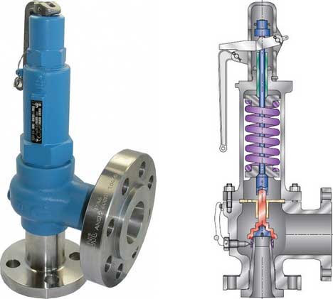
Below is an example of one of our pilot operated pressure relief valves in action; the cutaway demonstrates when high pressure is released from the system.
Air pressure relief valves can be applied to a variety of environments and equipment. Pressure relief valves are a safety valve used to keep equipment and the operators safe too. They"re instrumental in applications where proper pressure levels are vital for correct and safe operation. Such as oil and gas, power generation like central heating systems, and multi-phase applications in refining and chemical processing.
At Curtiss-Wright, we provide a range of different pressure relief valves based on two primary operations – spring-loaded and pilot operated. Spring-loaded valves can either be conventional spring-loaded or balanced spring-loaded.
Spring-loaded valves are programmed to open and close via a spring mechanism. They open when the pressure reaches an unacceptable level to release the material inside the vessel. It closes automatically when the pressure is released, and it returns to an average operating level. Spring-loaded safety valves rely on the closing force applied by a spring onto the main seating area. They can also be controlled in numerous ways, such as a remote, control panel, and computer program.
Pilot-operated relief valves operate by combining the primary relieving device (main valve) with self-actuated auxiliary pressure relief valves, also known as the pilot control. This pilot control dictates the opening and closing of the main valve and responds to system pressure. System pressure is fed from the inlet into and through the pilot control and ultimately into the main valve"s dome. In normal operating conditions, system pressure will prevent the main valve from opening.
The valves allow media to flow from an auxiliary passage and out of the system once absolute pressure is reached, whether it is a maximum or minimum level.
When the pressure is below the maximum amount, the pressure differential is slightly positive on the piston"s dome size, which keeps the main valve in the closed position. When system pressure rises and reaches the set point, the pilot will cut off flow to the dome, causing depressurization in the piston"s dome side. The pressure differential has reversed, and the piston will rise, opening the main valve, relieving pressure.
When the process pressure decreases to a specific pressure, the pilot closes, the dome is repressurized, and the main valve closes. The main difference between spring-loaded PRVs and pilot-operated is that a pilot-operated safety valve uses pressure to keep the valve closed.
Pilot-operated relief valves are controlled by hand and are typically opened often through a wheel or similar component. The user opens the valve when the gauge signifies that the system pressure is at an unsafe level; once the valve has opened and the pressure has been released, the operator can shut it by hand again.
Increasing pressure helps to maintain the pilot"s seal. Once the setpoint has been reached, the valve opens. This reduces leakage and fugitive emissions.
At set pressure the valve snaps to full lift. This can be quite violent on large pipes with significant pressure. The pressure has to drop below the set pressure in order for the piston to reseat.
At Curtiss-Wright we also provide solutions for pressure relief valve monitoring. Historically, pressure relief valves have been difficult or impossible to monitor. Our SmartPRV features a 2600 Series pressure relief valve accessorized with a wireless position monitor that alerts plant operators during an overpressure event, including the time and duration.
There are many causes of overpressure, but the most common ones are typically blocked discharge in the system, gas blowby, and fire. Even proper inspection and maintenance will not eliminate the occurrence of leakages. An air pressure relief valve is the only way to ensure a safe environment for the device, its surroundings, and operators.
A PRV and PSV are interchangeable, but there is a difference between the two valves. A pressure release valve gradually opens when experiencing pressure, whereas a pressure safety valve opens suddenly when the pressure hits a certain level of over pressurization. Safety valves can be used manually and are typically used for a permanent shutdown. Air pressure relief valves are used for operational requirements, and they gently release the pressure before it hits the maximum high-pressure point and circulates it back into the system.
Pressure relief valves should be subject to an annual test, one per year. The operator is responsible for carrying out the test, which should be done using an air compressor. It’s imperative to ensure pressure relief valves maintain their effectiveness over time and are checked for signs of corrosion and loss of functionality. Air pressure relief valves should also be checked before their installation, after each fire event, and regularly as decided by the operators.
Direct-acting solenoid valves have a direct connection with the opening and closing armature, whereas pilot-operated valves use of the process fluid to assist in piloting the operation of the valve.
A control valve works by varying the rate of fluid passing through the valve itself. As the valve stem moves, it alters the size of the passage and increases, decreases or holds steady the flow. The opening and closing of the valve is altered whenever the controlled process parameter does not reach the set point.
Control valves are usually at floor level or easily accessible via platforms. They are also located on the same equipment or pipeline as the measurement and downstream or flow measurements.
An industrial relief valve is designed to control or limit surges of pressure in a system, most often in fluid or compressed air system valves. It does so as a form of protection for the system and defending against instrument or equipment failure. They are usually present in clean water industries.
A PRV is often referred to as a pressure relief valve, which is also known as a PSV or pressure safety valve. They are used interchangeably throughout the industry depending on company standards.

Taylor Valve Technology® is a manufacturer leader in high-quality industrial valves. We deliver safety relief, high-pressure relief, and back pressure relief valves. Our wide array of choke and control valves and pilot-operated valve products are second to none. Products are designed for demanding industrial needs, meeting quality API and ASME Code requirements. High-demand oil & gas industry, chemical plants, power generators, and the processing industry depend on our valves for consistency and durability. Get effective flow control of liquid, steam, and gas. Valves ship from the Taylor Valve Technology, Inc. United States facility. Delivering worldwide, you can depend on quick turnaround times.

There is a wide range of safety valves available to meet the many different applications and performance criteria demanded by different industries. Furthermore, national standards define many varying types of safety valve.
The ASME standard I and ASME standard VIII for boiler and pressure vessel applications and the ASME/ANSI PTC 25.3 standard for safety valves and relief valves provide the following definition. These standards set performance characteristics as well as defining the different types of safety valves that are used:
ASME I valve - A safety relief valve conforming to the requirements of Section I of the ASME pressure vessel code for boiler applications which will open within 3% overpressure and close within 4%. It will usually feature two blowdown rings, and is identified by a National Board ‘V’ stamp.
ASME VIII valve- A safety relief valve conforming to the requirements of Section VIII of the ASME pressure vessel code for pressure vessel applications which will open within 10% overpressure and close within 7%. Identified by a National Board ‘UV’ stamp.
Full bore safety valve - A safety valve having no protrusions in the bore, and wherein the valve lifts to an extent sufficient for the minimum area at any section, at or below the seat, to become the controlling orifice.
Conventional safety relief valve -The spring housing is vented to the discharge side, hence operational characteristics are directly affected by changes in the backpressure to the valve.
Balanced safety relief valve -A balanced valve incorporates a means of minimising the effect of backpressure on the operational characteristics of the valve.
Pilot operated pressure relief valve -The major relieving device is combined with, and is controlled by, a self-actuated auxiliary pressure relief device.
Power-actuated safety relief valve - A pressure relief valve in which the major pressure relieving device is combined with, and controlled by, a device requiring an external source of energy.
Standard safety valve - A valve which, following opening, reaches the degree of lift necessary for the mass flowrate to be discharged within a pressure rise of not more than 10%. (The valve is characterised by a pop type action and is sometimes known as high lift).
Full lift (Vollhub) safety valve -A safety valve which, after commencement of lift, opens rapidly within a 5% pressure rise up to the full lift as limited by the design. The amount of lift up to the rapid opening (proportional range) shall not be more than 20%.
Direct loaded safety valve -A safety valve in which the opening force underneath the valve disc is opposed by a closing force such as a spring or a weight.
Proportional safety valve - A safety valve which opens more or less steadily in relation to the increase in pressure. Sudden opening within a 10% lift range will not occur without pressure increase. Following opening within a pressure of not more than 10%, these safety valves achieve the lift necessary for the mass flow to be discharged.
Diaphragm safety valve -A direct loaded safety valve wherein linear moving and rotating elements and springs are protected against the effects of the fluid by a diaphragm
Bellows safety valve - A direct loaded safety valve wherein sliding and (partially or fully) rotating elements and springs are protected against the effects of the fluids by a bellows. The bellows may be of such a design that it compensates for influences of backpressure.
Controlled safety valve - Consists of a main valve and a control device. It also includes direct acting safety valves with supplementary loading in which, until the set pressure is reached, an additional force increases the closing force.
Safety valve - A safety valve which automatically, without the assistance of any energy other than that of the fluid concerned, discharges a quantity of the fluid so as to prevent a predetermined safe pressure being exceeded, and which is designed to re-close and prevent further flow of fluid after normal pressure conditions of service have been restored. Note; the valve can be characterised either by pop action (rapid opening) or by opening in proportion (not necessarily linear) to the increase in pressure over the set pressure.
Direct loaded safety valve -A safety valve in which the loading due to the fluid pressure underneath the valve disc is opposed only by a direct mechanical loading device such as a weight, lever and weight, or a spring.
Assisted safety valve -A safety valve which by means of a powered assistance mechanism, may additionally be lifted at a pressure lower than the set pressure and will, even in the event of a failure of the assistance mechanism, comply with all the requirements for safety valves given in the standard.
Supplementary loaded safety valve - A safety valve that has, until the pressure at the inlet to the safety valve reaches the set pressure, an additional force, which increases the sealing force.
Note; this additional force (supplementary load), which may be provided by means of an extraneous power source, is reliably released when the pressure at the inlet of the safety valve reaches the set pressure. The amount of supplementary loading is so arranged that if such supplementary loading is not released, the safety valve will attain its certified discharge capacity at a pressure not greater than 1.1 times the maximum allowable pressure of the equipment to be protected.
Pilot operated safety valve -A safety valve, the operation of which is initiated and controlled by the fluid discharged from a pilot valve, which is itself, a direct loaded safety valve subject to the requirement of the standard.
The common characteristic shared between the definitions of conventional safety valves in the different standards, is that their operational characteristics are affected by any backpressure in the discharge system. It is important to note that the total backpressure is generated from two components; superimposed backpressure and the built-up backpressure:
Subsequently, in a conventional safety valve, only the superimposed backpressure will affect the opening characteristic and set value, but the combined backpressure will alter the blowdown characteristic and re-seat value.
The ASME/ANSI standard makes the further classification that conventional valves have a spring housing that is vented to the discharge side of the valve. If the spring housing is vented to the atmosphere, any superimposed backpressure will still affect the operational characteristics. Thiscan be seen from Figure 9.2.1, which shows schematic diagrams of valves whose spring housings are vented to the discharge side of the valve and to the atmosphere.
By considering the forces acting on the disc (with area AD), it can be seen that the required opening force (equivalent to the product of inlet pressure (PV) and the nozzle area (AN)) is the sum of the spring force (FS) and the force due to the backpressure (PB) acting on the top and bottom of the disc. In the case of a spring housing vented to the discharge side of the valve (an ASME conventional safety relief valve, see Figure 9.2.1 (a)), the required opening force is:
In both cases, if a significant superimposed backpressure exists, its effects on the set pressure need to be considered when designing a safety valve system.
Once the valve starts to open, the effects of built-up backpressure also have to be taken into account. For a conventional safety valve with the spring housing vented to the discharge side of the valve, see Figure 9.2.1 (a), the effect of built-up backpressure can be determined by considering Equation 9.2.1 and by noting that once the valve starts to open, the inlet pressure is the sum of the set pressure, PS, and the overpressure, PO.
Balanced safety valves are those that incorporate a means of eliminating the effects of backpressure. There are two basic designs that can be used to achieve this:
Although there are several variations of the piston valve, they generally consist of a piston type disc whose movement is constrained by a vented guide. The area of the top face of the piston, AP, and the nozzle seat area, AN, are designed to be equal. This means that the effective area of both the top and bottom surfaces of the disc exposed to the backpressure are equal, and therefore any additional forces are balanced. In addition, the spring bonnet is vented such that the top face of the piston is subjected to atmospheric pressure, as shown in Figure 9.2.2.
The bellows arrangement prevents backpressure acting on the upper side of the disc within the area of the bellows. The disc area extending beyond the bellows and the opposing disc area are equal, and so the forces acting on the disc are balanced, and the backpressure has little effect on the valve opening pressure.
Bellows failure is an important concern when using a bellows balanced safety valve, as this may affect the set pressure and capacity of the valve. It is important, therefore, that there is some mechanism for detecting any uncharacteristic fluid flow through the bellows vents. In addition, some bellows balanced safety valves include an auxiliary piston that is used to overcome the effects of backpressure in the case of bellows failure. This type of safety valve is usually only used on critical applications in the oil and petrochemical industries.
Since balanced pressure relief valves are typically more expensive than their unbalanced counterparts, they are commonly only used where high pressure manifolds are unavoidable, or in critical applications where a very precise set pressure or blowdown is required.
This type of safety valve uses the flowing medium itself, through a pilot valve, to apply the closing force on the safety valve disc. The pilot valve is itself a small safety valve.
The diaphragm type is typically only available for low pressure applications and it produces a proportional type action, characteristic of relief valves used in liquid systems. They are therefore of little use in steam systems, consequently, they will not be considered in this text.
The piston type valve consists of a main valve, which uses a piston shaped closing device (or obturator), and an external pilot valve. Figure 9.2.4 shows a diagram of a typical piston type, pilot operated safety valve.
The piston and seating arrangement incorporated in the main valve is designed so that the bottom area of the piston, exposed to the inlet fluid, is less than the area of the top of the piston. As both ends of the piston are exposed to the fluid at the same pressure, this means that under normal system operating conditions, the closing force, resulting from the larger top area, is greater than the inlet force. The resultant downward force therefore holds the piston firmly on its seat.
If the inlet pressure were to rise, the net closing force on the piston also increases, ensuring that a tight shut-off is continually maintained. However, when the inlet pressure reaches the set pressure, the pilot valve will pop open to release the fluid pressure above the piston. With much less fluid pressure acting on the upper surface of the piston, the inlet pressure generates a net upwards force and the piston will leave its seat. This causes the main valve to pop open, allowing the process fluid to be discharged.
When the inlet pressure has been sufficiently reduced, the pilot valve will reclose, preventing the further release of fluid from the top of the piston, thereby re-establishing the net downward force, and causing the piston to reseat.
Pilot operated safety valves offer good overpressure and blowdown performance (a blowdown of 2% is attainable). For this reason, they are used where a narrow margin is required between the set pressure and the system operating pressure. Pilot operated valves are also available in much larger sizes, making them the preferred type of safety valve for larger capacities.
One of the main concerns with pilot operated safety valves is that the small bore, pilot connecting pipes are susceptible to blockage by foreign matter, or due to the collection of condensate in these pipes. This can lead to the failure of the valve, either in the open or closed position, depending on where the blockage occurs.
The terms full lift, high lift and low lift refer to the amount of travel the disc undergoes as it moves from its closed position to the position required to produce the certified discharge capacity, and how this affects the discharge capacity of the valve.
A full lift safety valve is one in which the disc lifts sufficiently, so that the curtain area no longer influences the discharge area. The discharge area, and therefore the capacity of the valve are subsequently determined by the bore area. This occurs when the disc lifts a distance of at least a quarter of the bore diameter. A full lift conventional safety valve is often the best choice for general steam applications.
The disc of a high lift safety valve lifts a distance of at least 1/12th of the bore diameter. This means that the curtain area, and ultimately the position of the disc, determines the discharge area. The discharge capacities of high lift valves tend to be significantly lower than those of full lift valves, and for a given discharge capacity, it is usually possible to select a full lift valve that has a nominal size several times smaller than a corresponding high lift valve, which usually incurs cost advantages.Furthermore, high lift valves tend to be used on compressible fluids where their action is more proportional.
In low lift valves, the disc only lifts a distance of 1/24th of the bore diameter. The discharge area is determined entirely by the position of the disc, and since the disc only lifts a small amount, the capacities tend to be much lower than those of full or high lift valves.
Except when safety valves are discharging, the only parts that are wetted by the process fluid are the inlet tract (nozzle) and the disc. Since safety valves operate infrequently under normal conditions, all other components can be manufactured from standard materials for most applications. There are however several exceptions, in which case, special materials have to be used, these include:
Cast steel -Commonly used on higher pressure valves (up to 40 bar g). Process type valves are usually made from a cast steel body with an austenitic full nozzle type construction.
For all safety valves, it is important that moving parts, particularly the spindle and guides are made from materials that will not easily degrade or corrode. As seats and discs are constantly in contact with the process fluid, they must be able to resist the effects of erosion and corrosion.
The spring is a critical element of the safety valve and must provide reliable performance within the required parameters. Standard safety valves will typically use carbon steel for moderate temperatures. Tungsten steel is used for higher temperature, non-corrosive applications, and stainless steel is used for corrosive or clean steam duty. For sour gas and high temperature applications, often special materials such as monel, hastelloy and ‘inconel’ are used.
Standard safety valves are generally fitted with an easing lever, which enables the valve to be lifted manually in order to ensure that it is operational at pressures in excess of 75% of set pressure. This is usually done as part of routine safety checks, or during maintenance to prevent seizing. The fitting of a lever is usually a requirement of national standards and insurance companies for steam and hot water applications. For example, the ASME Boiler and Pressure Vessel Code states that pressure relief valves must be fitted with a lever if they are to be used on air, water over 60°C, and steam.
A test gag (Figure 9.2.7) may be used to prevent the valve from opening at the set pressure during hydraulic testing when commissioning a system. Once tested, the gag screw is removed and replaced with a short blanking plug before the valve is placed in service.
The amount of fluid depends on the particular design of safety valve. If emission of this fluid into the atmosphere is acceptable, the spring housing may be vented to the atmosphere – an open bonnet. This is usually advantageous when the safety valve is used on high temperature fluids or for boiler applications as, otherwise, high temperatures can relax the spring, altering the set pressure of the valve. However, using an open bonnet exposes the valve spring and internals to environmental conditions, which can lead to damage and corrosion of the spring.
When the fluid must be completely contained by the safety valve (and the discharge system), it is necessary to use a closed bonnet, which is not vented to the atmosphere. This type of spring enclosure is almost universally used for small screwed valves and, it is becoming increasingly common on many valve ranges since, particularly on steam, discharge of the fluid could be hazardous to personnel.
Some safety valves, most commonly those used for water applications, incorporate a flexible diaphragm or bellows to isolate the safety valve spring and upper chamber from the process fluid, (see Figure 9.2.9).
Shinjo Company focuses on manufacturing valves and pumps, including ball valves, check valves, gate valves, globe valves, butterfly valves, safety valves, hydraulic control valves, pressure reducing valves, needle valves, cast steel valves and diaphragm pumps, split case pumps, centrifugal pumps, multistage pumps, submersible pumps, etc.
Crosby pressure relief valves have maintained leadership in overpressure protection for over 140 years. The direct spring-operated safety and pressure relief valves are among the world’s most widely used for oil and gas production and refining, petrochemical and chemical processing, and conventional and nuclear power. Crosby pressure relief valves maintain the industry’s most extensive and capable flow facilities for testing in air, steam, and water.

The safety valves / pressure relief valves provided by Weldon mainly include spring-loaded safety valve, pilot-operated safety valve, bellow balanced safety valve and changeover valve (switch device). The calculation sheet could be provided for all projetc and all the safety valves are designed and manufactured according to API 2000, API PR520 and API 526.
Safety valve is the safe guard in the pressure vessels such as chemical plants, eletcric power boilers and gas storage tanks, acting as a protetcion equipment from exploding or damaging. The safety relief valve is opened automatically to relief when the system pressure exceeds the set pressure, and resumes closed when the system pressure bellow the set pressure.
The Spring-loaded safety valves is the most conventional safety valve, the spring load is preset to equal the force the inlet fluid exerts on the closed disk when the system pressure is at the set pressure of the valve. As the pressure exceeds a set value, the spring opens releasing the disc and the fluid flowing through the valve.
The Pilot-operated safety valves are composed of a "pilot valve" and a "main valve", differently from spring-loaded safety valves, the pressure is monitored and adjusted by the pilot valve, not the main valve. Pilot-operated safety valves are widely used for large size valve and high-pressure applications, which need lager torque and high reliability.
Bellow balanced safety valves are designed to reduce the effetc of back pressure accumulation, the "Bellows" located between the bonnet and the valve body, where maintained free from the effetc of back pressure, the opposing pressure on the inlet fluid is only generated by the spring without contribution from any sort of backpressure. The space enclosed by bellows is freely vented to air, the back pressure is expetced to be 10 - 50% of the set pressure. The Bellows can also protetc the spring and other trim components from corrosive media.
Breather Valves, also named Pressure/Vacuum Relief Valves, available with flanged outlets or vented to atmosphere, are special types of Relief Valves which are specifically designed for tank protetcion. Breather Valves are usually installed in the in-and out breathing lines of tanks, vessels and process equipment to prevent the of excessive pressure or vacuum which can unbalance the system or damage the storage vessels.
Changeover valves, also called Switch valves, are designed to connetc two safety valves to a single pressurized system, acting as the three ways devices for flow seletcion in a pipeline.
Through these Changeover valves, one of the two safety valves is in operation and ensures the protetcion of the system, the other safety valve is in "stand by" ready to come into operation if the first one must be changed or removed to maintenance. Changeover valves are often required for the continuous production.
Many electronic, pneumatic and hydraulic systems exist today to control fluid system variables, such as pressure, temperature and flow. Each of these systems requires a power source of some type, such as electricity or compressed air in order to operate. A pressure Relief Valve must be capable of operating at all times, especially during a period of power failure when system controls are nonfunctional. The sole source of power for the pressure Relief Valve, therefore, is the process fluid.
Once a condition occurs that causes the pressure in a system or vessel to increase to a dangerous level, the pressure Relief Valve may be the only device remaining to prevent a catastrophic failure. Since reliability is directly related to the complexity of the device, it is important that the design of the pressure Relief Valve be as simple as possible.
The pressure Relief Valve must open at a predetermined set pressure, flow a rated capacity at a specified overpressure, and close when the system pressure has returned to a safe level. Pressure Relief Valves must be designed with materials compatible with many process fluids from simple air and water to the most corrosive media. They must also be designed to operate in a consistently smooth and stable manner on a variety of fluids and fluid phases.
The basic spring loaded pressure Relief Valve has been developed to meet the need for a simple, reliable, system actuated device to provide overpressure protection.
The Valve consists of a Valve inlet or nozzle mounted on the pressurized system, a disc held against the nozzle to prevent flow under normal system operating conditions, a spring to hold the disc closed, and a body/Bonnet to contain the operating elements. The spring load is adjustable to vary the pressure at which the Valve will open.
When a pressure Relief Valve begins to lift, the spring force increases. Thus system pressure must increase if lift is to continue. For this reason pressure Relief Valves are allowed an overpressure allowance to reach full lift. This allowable overpressure is generally 10% for Valves on unfired systems. This margin is relatively small and some means must be provided to assist in the lift effort.
Most pressure Relief Valves, therefore, have a secondary control chamber or huddling chamber to enhance lift. As the disc begins to lift, fluid enters the control chamber exposing a larger area of the disc to system pressure.
This causes an incremental change in force which overcompensates for the increase in spring force and causes the Valve to open at a rapid rate. At the same time, the direction of the fluid flow is reversed and the momentum effect resulting from the change in flow direction further enhances lift. These effects combine to allow the Valve to achieve maximum lift and maximum flow within the allowable overpressure limits. Because of the larger disc area exposed to system pressure after the Valve achieves lift, the Valve will not close until system pressure has been reduced to some level below the set pressure. The design of the control chamber determines where the closing point will occur.
A safety Valve is a pressure Relief Valve actuated by inlet static pressure and characterized by rapid opening or pop action. (It is normally used for steam and air services.)
A low-lift safety Valve is a safety Valve in which the disc lifts automatically such that the actual discharge area is determined by the position of the disc.
A full-lift safety Valve is a safety Valve in which the disc lifts automatically such that the actual discharge area is not determined by the position of the disc.
A Relief Valve is a pressure relief device actuated by inlet static pressure having a gradual lift generally proportional to the increase in pressure over opening pressure. It may be provided with an enclosed spring housing suitable for closed discharge system application and is primarily used for liquid service.
A safety Relief Valve is a pressure Relief Valve characterized by rapid opening or pop action, or by opening in proportion to the increase in pressure over the opening pressure, depending on the application and may be used either for liquid or compressible fluid.
A conventional safety Relief Valve is a pressure Relief Valve which has its spring housing vented to the discharge side of the Valve. The operational characteristics (opening pressure, closing pressure, and relieving capacity) are directly affected by changes of the back pressure on the Valve.
A balanced safety Relief Valve is a pressure Relief Valve which incorporates means of minimizing the effect of back pressure on the operational characteristics (opening pressure, closing pressure, and relieving capacity).
A pilotoperated pressure Relief Valve is a pressure Relief Valve in which the major relieving device is combined with and is controlled by a self-actuated auxiliary pressure Relief Valve.
A poweractuated pressure Relief Valve is a pressure Relief Valve in which the major relieving device is combined with and controlled by a device requiring an external source of energy.
A temperature-actuated pressure Relief Valve is a pressure Relief Valve which may be actuated by external or internal temperature or by pressure on the inlet side.
A vacuum Relief Valve is a pressure relief device designed to admit fluid to prevent an excessive internal vacuum; it is designed to reclose and prevent further flow of fluid after normal conditions have been restored.
Many Codes and Standards are published throughout the world which address the design and application of pressure Relief Valves. The most widely used and recognized of these is the ASME Boiler and Pressure Vessel Code, commonly called the ASME Code.
is the calculated mass flow from an orifice having a cross sectional area equal to the flow area of the safety Valve without regard to flow losses of the Valve.
the pressure at which a Valve is set on a test rig using a test fluid at ambient temperature. This test pressure includes corrections for service conditions e.g. backpressure or high temperatures.
is the value of increasing static inlet pressure of a pressure Relief Valve at which there is a measurable lift, or at which the discharge becomes continuous as determined by seeing, feeling or hearing.
Because cleanliness is essential to the satisfactory operation and tightness of a safety Valve, precautions should be taken during storage to keep out all foreign materials. Inlet and outlet protectors should remain in place until the Valve is ready to be installed in the system. Take care to keep the Valve inlet absolutely clean. It is recommended that the Valve be stored indoors in the original shipping container away from dirt and other forms of contamination.
Safety Valves must be handled carefully and never subjected to shocks. Rough handling may alter the pressure setting, deform Valve parts and adversely affect seat tightness and Valve performance.
When it is necessary to use a hoist, the chain or sling should be placed around the Valve body and Bonnet in a manner that will insure that the Valve is in a vertical position to facilitate installation.
Many Valves are damaged when first placed in service because of failure to clean the connection properly when installed. Before installation, flange faces or threaded connections on both the Valve inlet and the vessel and/or line on which the Valve is mounted must be thoroughly cleaned of all dirt and foreign material.
Because foreign materials that pass into and through safety Valves can damage the Valve, the systems on which the Valves are tested and finally installed must also be inspected and cleaned. New systems in particular are prone to contain foreign objects that inadvertently get trapped during construction and will destroy the seating surface when the Valve opens. The system should be thoroughly cleaned before the safety Valve is installed.
The gaskets used must be dimensionally correct for the specific flanges. The inside diameters must fully clear the safety Valve inlet and outlet openings so that the gasket does not restrict flow.
For flanged Valves, draw down all connection studs or bolts evenly to avoid possible distortion of the Valve body. For threaded Valves, do not apply a wrench to the Valve body. Use the hex flats provided on the inlet bushing.
Safety Valves are intended to open and close within a narrow pressure range. Valve installations require accurate design both as to inlet and discharge piping. Refer to International, National and Industry Standards for guidelines.
The Valve should be mounted vertically in an upright position either directly on a nozzle from the pressure vessel or on a short connection fitting that provides a direct, unobstructed flow between the vessel and the Valve. Installing a safety Valve in other than this recommended position will adversely affect its operation.
Discharge piping should be simple and direct. A "broken" connection near the Valve outlet is preferred wherever possible. All discharge piping should be run as direct as is practicable to the point of final release for disposal. The Valve must discharge to a safe disposal area. Discharge piping must be drained properly to prevent the accumulation of liquids on the downstream side of the safety Valve.
The weight of the discharge piping should be carried by a separate support and be properly braced to withstand reactive thrust forces when the Valve relieves. The Valve should also be supported to withstand any swaying or system vibrations.
If the Valve is discharging into a pressurized system be sure the Valve is a "balanced" design. Pressure on the discharge of an "unbalanced" design will adversely affect the Valve performance and set pressure.
The Bonnets of balanced bellows safety Valves must always be vented to ensure proper functioning of the Valve and to provide a telltale in the event of a bellows failure. Do not plug these open vents. When the fluid is flammable, toxic or corrosive, the Bonnet vent should be piped to a safe location.
It is important to remember that a pressure Relief Valve is a safety device employed to protect pressure vessels or systems from catastrophic failure. With this in mind, the application of pressure Relief Valves should be assigned only to fully trained personnel and be in strict compliance with rules provided by the governing codes and standards.

A safety Relief Valve is a pressure Relief Valve characterized by rapid opening or pop action, or by opening in proportion to the increase in pressure over the opening pressure, depending on the application and may be used either for liquid or compressible fluid.
A conventional safety Relief Valve is a pressure Relief Valve which has its spring housing vented to the discharge side of the Valve. The operational characteristics (opening pressure, closing pressure, and relieving capacity) are directly affected by changes of the back pressure on the Valve.
Operational characteristics of this pressure relief valve are directly affected by back pressure changes. For conventional safety relief valve, only the superimposed back pressure affects the opening characteristic and set pressure value, but the combined back pressure (superimposed backpressure plus built up backpressure) affects the blowdown characteristic and re-seat pressure value. A conventional pressure relief valve is not used when the built-up backpressure is greater than 10% of the set pressure at 10% overpressure. A higher maximum allowable built-up backpressure may be used for overpressure greater than 10%.
Advantages of conventional relief valves are reliability and versatility. These relief valves are most reliable when sized properly and can be used in a wide range of services.
Disadvantage of these relief valves is the effect of backpressure on the relieving pressure of valve and hence pressure accumulation in the protected equipment. Also for high built up backpressure values generated by higher pressure loss in the relief valve discharge line, chattering can occur in these relief valves.
A balanced safety Relief Valve is a pressure Relief Valve which incorporates means of minimizing the effect of back pressure on the operational characteristics (opening pressure, closing pressure, and relieving capacity).
Effect of back pressure on the operational characteristics of the valve is minimized by incorporating bellows. The bellows encircle an area equal to the inlet orifice area. This area is maintained free from the effect of back pressure from the discharge side of the relief valve. The space enclosed by bellows is freely vented to air. Thus the opposing pressure on the inlet fluid is generated by the spring alone without contribution from any sort of backpressure. For these relief valves allowable back pressure is 10 - 50% of the set pressure.
Advantage of using balanced bellows relief valves is no effect of back pressure on the relieving pressure and pressure accumulation. The spring is isolated from discharge fluid from the bellows, hence risk of corrosion mitigated. These relief valves get special consideration when there is high combined backpressure on the relief valve.
Many Codes and Standards are published throughout the world which address the design and application of pressure Relief Valves. The most widely used and recognized of these is the ASME Boiler and Pressure Vessel Code, commonly called the ASME Code.
The primary purpose of a safety valve is to protect life, property and the environment. Safety valves are designed to open and release excess pressure from vessels or equipment and then close again.
The function of safety valves differs depending on the load or main type of the valve. The main types of safety valves are spring-loaded, weight-loaded and controlled safety valves.
Regardless of the type or load, safety valves are set to a specific set pressure at which the medium is discharged in a controlled manner, thus preventing overpressure of the equipment. In dependence of several parameters such as the contained medium, the set pressure is individual for each safety application.

In the United States, use of such devices was spurred by the 1,700 boiler explosions that resulted in 1,300 deaths from 1905 to 1911. By 1915, the American Society of Mechanical Engineers (ASME) published its first boiler code, Rules for Construction of Stationary Boilers and Allowable Working Pressures, incorporating rules for construction and installation of safety valves for boilers.
The primary purpose of a pressure relief valve is to open to relieve excess pressure, reclose and prevent further flow of fluid after normal conditions have been restored (Figure 5). A secondary purpose is to minimize damage to other system components through operation of the pressure relief valve itself. A pressure relief valve designed under ASME Boiler and Pressure Vessel Code is stamped with the certification mark, and one of the certification designators: V, NV, HV, UV, UV3 or TV.
The many types of pressure relief valves that exist are based on different designs and construction. Generally, they’re classified as: safety relief valves, relief valves and safety valves.
A conventional safety relief valve is a spring-loaded pressure relief valve characterized by a rapid-opening pop action. Conventional safety relief valves are used for applications where excessive variable or built-up back pressure is not present in the system. The operational characteristics of these valves are directly affected by changes in the back pressure on the valve.
The working principle of a conventional spring-loaded safety relief valve is based on the balance of force. The spring load is preset to equal the force the inlet fluid exerts on the closed disk when the system pressure is at the set pressure of the valve.
The disk remains seated on the nozzle in the closed position when the inlet pressure is below the set pressure. The valve opens when the inlet pressure exceeds set pressure, overcoming the spring force. The valve recloses when the inlet pressure is reduced to a level below the set pressure.
Once the valve has opened, an additional pressure buildup at C occurs. This additional force at C causes the disk to lift substantially at pop. The valve closes when the inlet pressure has dropped sufficiently below the set pressure. The pressure at which the valve resets is called the closing pressure. The difference between the set pressure and closing pressure is the blowdown.
In the design of a conventional valve, an important consideration is seat leakage. This leakage can result in continuous loss of system fluid and may cause progressive damage to the valve seating surface. Based on the seating material, conventional valves are classified as:
Metal-seated valves. Metal-to-metal seats are commonly made from stainless or other hard alloy steels and are normally used for high-temperature applications such as steam and corrosive media applications for processing a wide variety of chemicals.
Soft-seated valve. An alternative to metal is resilient disks that can be fixed to either or both the seating surfaces where tighter shut-off is required. They are common for gas or liquid applications. These inserts may be made from a number of different materials, but Vinton, nitrile or EPDM (ethylene propylene diene monomer) are the most common.
Balanced bellows with auxiliary balancing piston. With this valve, the balanced bellows seal the body and fluid stream from the bonnet and working parts. The auxiliary balancing piston assures proper valve performance by compensating for back pressure in case the bellows fail.
The primary difference between a pilot-operated safety relief valve and a spring-loaded pressure relief valve is that the pilot-operated valve uses process pressure to keep the valve closed instead of a spring. A pilot is used to sense process pressure and to pressurize or vent the dome pressure chamber, which controls the valve opening or closing.
A pilot-operated safety relief valve consists of the main valve, a floating, unbalanced piston assembly, and an external pilot. The pilot controls the pressure on the top side of the main valve’s unbalanced moving chamber. A resilient seat is normally attached to the lower end.
At below-set level, the pressure on opposite sides of the moving member is equal. When the set pressure is reached, the pilot opens and depressurizes the cavity on the top side so the unbalanced member moves upward, causing the main valve to relieve. When the process pressure decreases to a predetermined pressure, the pilot closes, the cavity above the piston is depressurized and the main valve closes.
The valves operate bubble tight at higher operating pressure-to-set pressure ratios, allowing operators to run very close to the vessel’s maximum allowable working pressure.
Valve movement to open or close is fully controlled by a source of power such as electricity, steam or water (hydraulic). The valve may discharge to the atmosphere or to a container that is at lower pressure. The discharge capacity can be affected by downstream conditions.
Power-actuated safety relief valves are used mostly for forced-flow steam generators with no fixed steam or waterline. They are also used in nuclear power plants.
A temperature and pressure-actuated safety relief valve (also called a T&P safety relief valve) is a pressure relief valve that may be actuated by temperature or pressure on the inlet side (Figure 10).
Such a valve is designed for dual purposes. First, the T&P valve prevents temperature within a vessel from rising above a specified limit (generally 210°F or 98°C). Second, the T&P valve prevents pressure in the vessel from rising above a specified value.
A relief valve is actuated by inlet static pressure and a gradual lift that is generally proportional to the increase in pressure over opening pressure. Such a valve can be provided with enclosed spring housing suitable for closed discharge system applications.
Relief valves are commonly used in liquid systems, especially for lower capacities and thermal expansion applications. They also can be used on pump systems.
Adjustable relief valves feature convenient adjustment of the pressure setting through the outlet port. They are suitable for non-vented or vented inline applications in chemical, petrochemical and high-purity gas industries.
Electronic relief valves (ERVs) are pilot-operated relief valves that offer zero leakage. The ERV package combines a zero-leakage isolation valve with electric controls to monitor and regulate system pressure. These valves provide protection either in a capacity-relieving function or simply in an overpressure-protection application.
Safety valves are typically used for boiler overpressure protection and other applications such as downstream from pressure-reducing controls. These valves are installed wherever the maximum allowable working pressure of boilers is likely to be exceeded. Safety valves are also used for compressible gases, in particular for steam and air.
Safety valves are classified according to the lift. The term “lift” refers to the amount of travel the valve undergoes as it moves from its closed position to the position required to produce the certified discharge capacity.
Low-lift are safety valves in which the valve lifts a distance of 1/24th of the bore diameter. Since the valve has a small lift, the capacity is much lower than other types.
High-lift are safety valves in which the valve lifts a distance of at least 1/12th of the bore diameter. High-lift valves are used on compressible fluids, where their action is more proportional.
Full-lift are safety valves for which the valve lifts a distance of at least 1/4th of the bore diameter. Full-lift valves are considered the best choice for general steam applications.
Test gags are used to hold the safety valve closed while equipment is subjected to a hydrostatic test. To avoid damage to the spindle and/or seat, care is required so the gag screw is not tightened.
Lifting mechanisms are used to open the pressure relief valves when the pressure under the valve disk is lower than the set pressure. These mechanisms are available in three basic types: plain lever, packaged lever and air-operated lifting devices.
A key advantage of selecting a butterfly valve is the reduction of space and weight to a system compared with other options such as ball, check, globe or gate valves.

Because a safety valve is often the last device to prevent catastrophic failure under pressure conditions, it is important that the valve works at all times i.e. it must be 100% reliable.
Safety valves should be installed wherever the maximum allowable working pressure of a system or pressure containing vessel is likely to be exceeded, in particular under fault conditions due to the failure of another piece of equipment in the system.
The term “Safety Valve” and “Relief Valve” are generic terms to describe a variety of pressure relief devices. A wide range is available based on the application and required performance criteria. The different designs are required to meet numerous national standards.
The images below show the devastating results of a failed Safety valve (due to poor maintenace) or ones which have been incorrectly sized, installed or maintained.
A spring-loaded pressure relief valve which is designed to open to relieve excess pressure and to reclose and prevent the further flow of fluid after normal conditions have been restored. It is characterised by a rapid-opening "pop" action or by opening in a manner generally proportional to the increase in pressure over the opening pressure. It may be used for either compressible or incompressible fluids, depending on design, adjustment, or application.
Relief valve - A pressure relief device actuated by inlet static pressure having a gradual lift generally proportional to the increase in pressure over opening pressure.
Safety relief valve - A pressure relief valve characterised by rapid opening or pop action, or by opening in proportion to the increase in pressure over the opening pressure, depending on the application, and which may be used either for liquid or compressible fluid.
Safety valve - A valve which automatically, without the assistance of any energy other than that of the fluid concerned, discharges a quantity of the fluid so as to prevent a predetermined safe pressure being exceeded, and which is designed to re-close and prevent further flow of fluid after normal pressure conditions of service have been restored.
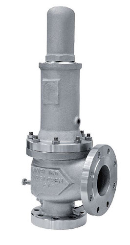
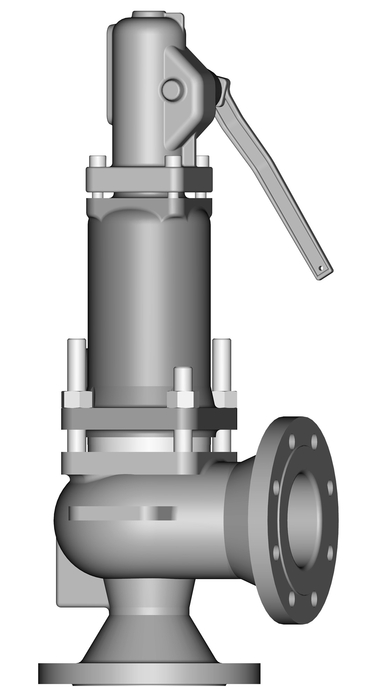
The images below show a standard Relief valve and a standard Safety valve from a well-known UK manufacturer. Each manufacturer does things slightly differently however all of the basic components and principles of operation are the same. As described previously, a safety valve differs from a relief valve in that it opens rapidly once the set pressure has been reached. For the same inlet size and with the valve in the closed position, the surface area that the pressure on the inlet side will see is the same. When the set pressure is reached and the valve starts to open, the disk on a Safety valve is larger (see the diagrams below) and hence the same pressure then sees a much larger surface area and consequently the force increases greatly causing the valve to open quickly and hence the characteristic pop action.
The image below shows the above Safety valves and Relief valves dismantled. The disk diameter on the 1" (DN25) Safety valve is only 7mm larger than on the Relief valve which doesnt sound like much, but when you calculate the areas it is an increase of 36%.
This diagram represents a Safety valve in its very simplest form. The force acting on the inlet side of the disk is acting against the force applied by the spring plus the force applied by the back pressure on the top of the disk.
The valve remains closed when(PI x Ab) < Fs + (PB x At), is in equilibrium when(PI x Ab) = Fs + (PB x At) and opens when(PI x Ab) > Fs + (PB x At) were PI = Inlet pressure, PB = Back pressure, At = Top of disk area, Ab = Bottom of disk area. Things to notice from this design are that if PB is variable and quite large relative to PI, then this will cause the pressure at which the valve opens to vary which is undesirable. The following two designs (Fig 3 & Fig 4) are available that eliminate the effect of back pressure on the set pressure.
The bellows prevents backpressure acting on the top side of the disk. In relation to the piston there is no top side within the main body of the valve hence again the back pressure cannot affect the set pressure. Bellows failure is an important concern in critical applications where a very precise set pressure is required. In these cases some mechanism to detect a leak of process medium out of the top vent would be implemented. Piston designs are not usually found in conventional Safety valves but are more common in Pilot Operated Safety valves.
API 520 Practice Guidelines: a conventional design should not typically be used when the built-up backpressure is greater than 10% of the set pressure at 10% over pressure. European standard EN ISO 4126: the built-up backpressure should be limited to 10% of the set pressure when the valve is discharging at the certified capacity.
In a conventional design (no bellows), the superimposed backpressure will affect the opening characteristic and set value, but the combined backpressure will alter the closing (blowdown) and re-seat value.
Overpressure is the percentage over the set pressure by which the valve is fully open. The blowdown is the percentage below the set pressure by which the valve is fully closed.
The basic elements of the design are right angle pattern valve body, inlet can be either a full nozzle or a semi-nozzle type. With a full nozzle design has the “wetted” inlet tract formed from one piece (as per figure 6) with the seat integrated into the top of the nozzle. The internal bore of the nozzle and the disc is the only part of the valve that is exposed to the process fluid with the valve in the closed position. A semi-nozzle design consists of a seating ring fitted into the body.The disc is held onto the seat by the stem, with the downward force coming from the compression on the spring mounted in the bonnet. The amount of compression on the spring is adjusted by the spring adjuster under the cap.
Unless bellows or diaphragm sealing is used, process fluid will enter the spring housing (or bonnet). The amount of fluid depends on the particular design of safety valve. If emission of this fluid into the atmosphere is acceptable, the spring housing may be vented to the atmosphere - an open bonnet. This is usually advantageous when the safety valve is used on high temperature fluids or for boiler applications as, otherwise, high temperatures can relax the spring, altering the set pressure of the valve. However, using an open bonnet exposes the valve spring and internals to environmental conditions, which can lead to damage and corrosion of the spring.
When the fluid must be completely contained by the safety valve (and the discharge system), it is necessary to use a closed bonnet, which is not vented to the atmosphere. This type of spring enclosure is almost universally used for small screwed valves and, it is becoming increasingly common on many valve ranges since, particularly on steam, discharge of the fluid could be hazardous to personnel.
A lifting mechanism is recommended to test for correct valve operation at all times where corrosion, caking, or any deposit could prevent the opening operation.
Foreign particles can lodge under the seat of the valve when it discharges. The lifting lever allows you to lift the valve and flush the obstruction. Pressure relief valves for Section VIII require a lift lever on all air, steam, and hot water valves used at temperatures over 60 degC. Typically used where periodic testing of the valve in location is desired to assure its operation. With an Open lifting lever design, when the valve discharges, fluid media will escape into the atmosphere around the open lifting lever assembly. If this is not desirable or when back pressure is present you would select a Packed Lifting Lever design.
As described above, this type is selected where leakage of the media to the atmosphere during valve discharge or during back pressure would be un-desirable. A packed lever design is a completely sealed assembly.
Under certain circumstances i.e. under the start-up conditions of a plant or to pressure test the system in a controlled environment, it may be required that the valve is prevented from opening.This is achieved by screwing the bolt (shown on the wire) into the cap which screws down onto the stem and prevents it lifting. Obviously it is important that test gags are removed prior to placing the valve into service.
The bellows is designed to cover the same area on the back of the disc equal to the seat area hence the back pressure will have no effect on the set pressure. See the previous section “Basic Safety Valve Principles”. Bellows also protects the spindle, spindle guide and spring from the process medium.
A disc is held against the nozzle by a spring, which is contained in a cast bonnet. The spring is adjusted by a compression screw to permit the calibration of opening or set pressure. An adjustable nozzle ring, threaded onto the nozzle, controls the geometry of the fluid exit control chamber (also known as a huddling chamber). The control chamber (huddling chamber) geometry is very important in controlling valve opening and closing pressures and stability of operation. The nozzle ring is locked into position by a ring pin assembly as shown in Figure 15 below.
Under normal system operation the valve remains in the closed position because the spring force (Fs) is greater than the system pressure acting on the internal nozzle seating area (PA). If system pressure increases to a point when these forces are equal, then the set pressure is reached. The disc lifts and fluid flows through the valve. When pressure in the system returns to a safe level, the valve closes.
Just prior to reaching set point, the pressure relief valve leaks system fluid into the huddling chamber. The fluid now acts on a larger area of the disc inside the huddling chamber (PAh), causing the valve to experience an instantaneous increase in the opening force. Refer t


 8613371530291