
crosby pressure safety valve made in china

Crosby pressure relief valves have maintained leadership in overpressure protection for over 140 years. The direct spring-operated safety and pressure relief valves are among the world’s most widely used for oil and gas production and refining, petrochemical and chemical processing, and conventional and nuclear power. Crosby pressure relief valves maintain the industry’s most extensive and capable flow facilities for testing in air, steam, and water.

Crosby pressure relief valves have been on the forefront of overpressure protection for more than 140 years. The direct spring-operated safety and pressure relief valves are among the world’s most widely used in oil and gas production and refining, petrochemical and chemical processing, and conventional and nuclear power industries. Crosby pressure relief valves uphold the industry’s most extensive and capable flow facilities for testing gas, liquid, steam and multi-phase applications.
Crosby is part of Emerson’s pressure relief portfolio, a complete range of standard and customized solutions, whatever need you have for overpressure protection.
Emerson is an industry leader in pressure relief valve technology. A single point provider, they offer an extensive product range for reliable performance with lower valve life-cycle costs and unique solutions. Their unrivaled engineering and technical expertise results in pressure management products, application solutions and services that can positively affect your business, safety, operations and the bottom line. Their engineering teams have designed testing equipment and procedures that assure optimum valve performances under all service conditions.
Facilities have cryogenic flow testing capabilities down to -320°F / -196°C, and flow steam testing, making them amongst the largest in the world that are used for research, experimentation and control of emissions on relief valves, like Crosby’s.
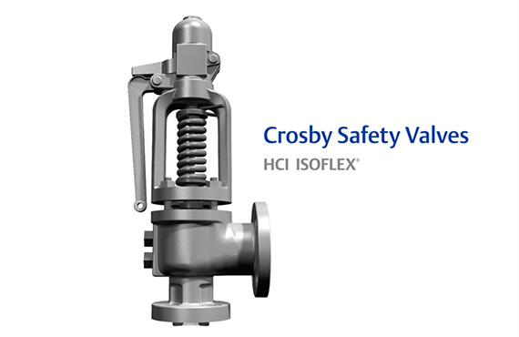
Crosby’s H-Series direct spring-operated safety valves are the trusted and proven solution to thorough overpressure protection for steam safety applications such as economizers, steam drums, superheaters, reheaters and more.
Crosby’s J-Series valves provide high quality and dependable overpressure protection for air, gas, steam, vapor, liquid and two-phase applications in one simple design.
Crosby leads the way in pressure relief valve technology. Explore high quality and dependable overpressure protection and phase applications in their catalog of relief valves.

Relieving capacities certified by National Board of Boiler and Pressure Vessel Inspectors. Certification includes air and steam for Series 800, and air, steam and water for Series 900.
Spring standardization. Standard Series 800 and Series 900 OMNI-TRIM® pressure relief valves are suitable for inlet temperatures to 750°F [399°C], using a 17-7PH stainless steel spring.
Series 800 pressure relief valves have an external blowdown adjustment allowing for short blowdown, smaller differential between operating and set pressures, and reduced product loss.

The 2700 Series pressure relief valve, also known as an expansion relief valve, features a superior design that handles air, steam, vapor, and liquid services. In addition, the fixed blowdown design simplifies testing and repair, and the maximum interchangeability of parts allows for easy maintenance.
Expansion relief valves, also referred to as PRV’s, pressure relief valves, or safety valves, are designed to protect system tanks from overpressure, therefore a vital component. Overpressure can be caused by several things, including failure of an expansion vessel or a pressure-reducing valve.
Carrying on pressure tests on systems consists of adjusting the valve set pressure, performing a seat l,eakage test and a backpressure test. The set pressure test is always performed first.
Expansion relief valves are used in a range of industry demanding applications where pressure levels are critical for operation. Applications and industries include:
Air pressure relief valves, also known as PRVs or safety release valves, are installed to prevent pressure buildup. The valve opens slowly to release pressure when the level becomes too high.
If the pressure within an air compressor system gets too high, one of the components inside could explode. Essentially, pressure relief valves are designed to prevent uncontrolled depressurization events from occurring, protecting surrounding nearby equipment and employees during overpressure events.
Test the secondary pressure zone of all valves exceeding 1" inlet size with air or other suitable gas at a pressure of at least 30 psi. Use a suitable leak detection solution to verify tightness of all gasket joints and vent/drain plugs.
Expansion relief valves are often known as pressure relief valves and for a good reason. They come with a preset pressure built into their design to ensure once the valve recognizes the pressure limit, it opens to release the pressure-flow (fluid of compressed air) safely.
It’s advisable to permanently mount pressure relief valves in a vertical position so the spindle sits correctly and can operate effectively. Overtightening the valve can cause damage to the inlet and cause leakage too. For the inlet piping, keep it short and direct, it should have a shorter diameter than the valve, and it should always be far away from turbulence or vibration in the operating system.
A pressure relief valve can encounter overpressure or failure for many reasons, but the most common reasons are typically blocked discharge in the system, contaminants like dirt, rust, or sludge, or even valve misalignment can cause the pressure relief valve to fail. Maintenance and proper inspection periodically can help eliminate leakages, allowing a safe environment for operation and the operators.

If the determined valve type and model are provided by the customer, the customer should correctly explain the meaning and requirements of its model, and sign the contract under the conditions that the supply and demand sides understand and agree.

Pressure relief valves (PRVs) are a critical line of defense for pressure vessel protection in the power industry. Generating facilities worldwide depend upon these devices to sense and quickly relieve overpressure conditions to avoid catastrophic damage during process upsets. To ensure these valves will perform as expected, mechanical engineering regulatory bodies mandate the valves be tested on a routine basis.
Some installations make the option of pulling the valve for servicing and testing very difficult. This is particularly true for large size valves, and in the nuclear power industry where valves may be located inside containment areas, making valve access particularly problematic. Fortunately, there is another approved method of testing relief valves for this situation, and this alternative solution is the subject of this article.
PRVs are relatively, but deceptively, simple devices. They consist of an inlet nozzle attached to the process, which is blocked by a disc held tightly on the nozzle seat (Figure 1). The disc is kept closed by a spring, with adjustments carefully made to dial in the setpoint of the valve.
1. A pressure relief valve (PRV) protects equipment by automatically opening to vent process media when the pressure in the inlet nozzle overcomes the downward force of the spring. Courtesy: Emerson
When the process reaches set pressure, the upward force of the process media offsets the downward force of the spring and the disc lifts off the seat. The process media is relieved through the valve outlet until pressure falls below the setpoint. At this point, the downward force of the spring overcomes the upward force of the process media, and the valve closes.
To ensure the PRV will function when called into action, the American Society of Mechanical Engineers (ASME) mandates relief valves be functionally checked on a routine basis. Typically, a plant will pull smaller valves from their installed position during process outages, and then inspect and test them in a shop environment to confirm they will function as desired and open at the proper pressure setpoint. However, this method of testing is not so easily achieved in certain cases.
Some relief valves are very large and/or located in difficult to reach areas. Others are welded into place and not easily removed from the process. Valves inside nuclear containment areas are particularly troublesome since access to these areas is usually restricted, with strict adherence to extensive protocols required for entry.
To handle these challenging situations, ASME provides alternate means of testing relief valves, as documented in ASME Performance Test Code (PTC) 25 Pressure Relief Devices. These test methods include in-service testing, which allows the plant to functionally test the relief valve without removing it from the process. This in-situ test method can be quite accurate and effective, but only if it is performed correctly with the right equipment.
Service and testing of PRVs is typically performed during regular maintenance outages as defined by ASME guidelines. Operating pressures and temperatures are brought down to levels conducive for servicing, and the PRVs are tested by maintenance technicians. For this type of in-service, or in-situ testing, lift assist devices are used in conjunction with these lower system pressures to verify the PRV will operate at the setpoint, within allowable tolerances.
ASME-approved, in-service testing allows the use of lift assist devices attached to the spindle of the valve with adapters, along with other test apparatus to perform set pressure verification testing. The equipment shown in Figure 2 allows a carefully monitored lift force to be applied to the spindle of a PRV until the disc lifts off the seat. The process pressure and the lift force are known, enabling this type of a computer-driven system to determine the setpoint of the PRV, and confirm that it falls within tolerance. This specific type of lift assist equipment is known as a set pressure verification device (SPVD).
2. A portable lift assist, or auxiliary lift device, allows a PRV to be functionally tested without removing the valve from the process. Courtesy: Emerson
There are several other types of lift assist devices available to perform in-service set pressure verification testing, with varying degrees of effectiveness. For most applications, an SPVD is the preferred method of in-service testing.
SPVDs utilize highly accurate pressure sensors to measure the process pressure and determine the lift force being applied. These sensors include automatic calibration and diagnostics by the SPVD computer-based controller to confirm the sensors are operating correctly prior to each test.
A linear variable differential transformer (LVDT) is used to detect the earliest sign of valve stem movement, in the range of 0.020 inch, well below the point where the valve will go into full lift. At this time, force and pressure values are obtained, and the test is concluded to avoid wasteful discharge of the process media and minimize seat damage.
Perhaps the most important feature of an SPVD is a fully automated test execution system (Figure 3). This system incorporates an industrially hardened portable laptop computer running automated test protocols, including calibration and diagnostics. The computer can print out certified test results and be connected to up to five relief valves, simplifying and speeding test execution.
3. A technician performs a fully automated set pressure verification device (SPVD) test. Calibration, diagnostics, and test functions are built into the system, allowing plant personnel to execute consistent and accurate PRV tests. Courtesy: Emerson
Some other types of lift devices are more manual and can only be operated by trained personnel, typically provided by the lift device vendor at considerable expense. However, a fully automated SPVD allows most plant technicians to perform PRV set pressure verification tests as needed. The most useful lift assist devices can be installed on a wide variety of PRVs, rather than just on those from specific manufacturers. Ideally, the lift device should be lightweight and easily adaptable to fit a wide range of relief valves.
Cost and scheduling benefits can be realized from self-test execution, and fully automated PRV set pressure testing also helps ensure consistent and accurate test results, regardless of personnel experience. SPVDs typically provide ASME-certified test results with a proven test accuracy of less than +/–1% error, significantly below the typical ASME test accuracy threshold of +/–3%.
SPVD is often the preferred choice to address a number of challenging PRV test issues. Some valves are very large or not easily removed, so an in-service test is clearly the least costly option (Figure 4). This can especially be true for large relief valves that are welded into the process piping.
4. Emerson’s Crosby SPVD is being used to perform an in-service test on this American Society of Mechanical Engineers (ASME) Section III Class 2 safety valve. Installation and testing of the SPVD does not restrict the PRV from operating should process conditions require the valve to open in service. Courtesy: Emerson
Inside nuclear power plants, many large PRVs are located within containment buildings, where access is extremely limited. For critical PRVs in these areas, SPVD lift assist heads and adapters can be permanently installed on the valves, with test cables routed outside the restricted zone and connected to a computer controller.
Since this type of lift device does not impact valve performance during normal operation or overpressure conditions, the PRV can still operate as necessary. Tests can be remotely performed from outside the containment building by simply plugging the cables into a test system and executing the test. Such an installation allows a plant to safely operate under normal conditions and test their critical PRVs on an as-needed basis, while avoiding any potential radiation exposure.
A well-designed lift assist device is a valuable addition to a plant’s PRV maintenance toolset. Every PRV is required to undergo regular in-service testing requirements as defined by the ASME Operation and Maintenance of Nuclear Power Plants code. The code permits use of lift assist devices to perform set pressure verification testing, which is particularly useful in situations where removing the valve from its installed position is not practical. The right lift assist device allows plant personnel to safely execute scheduled maintenance during outage events, or during operation in other cases, ensuring that critical PRVs are functioning per design with correctly adjusted setpoints.
A fully automated SPVD allows plant personnel to perform these tests consistently and accurately, freeing users to schedule and execute PRV tests, without the need for outside vendor involvement. This saves time and cost, and it removes dependence on a single vendor as a service provider. SPVD also provides a means for nuclear power plants to remotely test their critical relief valves, while avoiding exposure in containment areas.
If faced with a PRV testing challenge, plant personnel should consider lift-assist devices, such as an SPVD, as a potential solution. They meet ASME requirements for set pressure verification testing, and the fully automated operation of SPVD guarantees reliable test results, while providing many other benefits noted in this article.
—June DelGrossois the sales director for North America Nuclear and Navy at Emerson for its flow control products. She has worked for a variety of companies, filling roles such as Valve and Instrument Design Engineer, Product Engineering Manager, and Global Product Technical Leader.
There are various safety valves available to meet various applications and performance criteria demanded by various industries. Furthermore, national standards determine many types of varied safety valves.
Standard ASME I and ASME VIII standards for boiler applications and vessels and ASME / ANSI PTC 25.3 standards for safety valves and relief valves provide the following definition. These standards set performance characteristics and define various types of safety valves used:
ASME I valve - A safety relief valve conforming to the requirements of Section I of the ASME pressure vessel code for boiler applications which will open within 3% overpressure and close within 4%. It will usually feature two blowdown rings and is identified by a National Board ‘V’ stamp.
ASME VIII valve - A safety relief valve conforming to the requirements of Section VIII of the ASME pressure vessel code for pressure vessel applications which will open within 10% overpressure and close within 7%. Identified by a National Board ‘UV’ stamp.
Full bore safety valve - A safety valve having no protrusions in the bore, and wherein the valve lifts to an extent sufficient for the minimum area at any section, at or below the seat, to become the controlling orifice.
Conventional safety relief valve - The spring housing is vented to the discharge side, hence operational characteristics are directly affected by changes in the backpressure to the valve.
Balanced safety relief valve - A balanced valve incorporates a means of minimizing the effect of backpressure on the operational characteristics of the valve.
Pilot operated pressure relief valve - The major relieving device is combined with, and is controlled by, a self-actuated auxiliary pressure relief device.
Power-actuated safety relief valve - A pressure relief valve in which the major pressure-relieving device is combined with, and controlled by, a device requiring an external source of energy.
Standard safety valve - A valve which, following the opening, reaches the degree of lift necessary for the mass flowrate to be discharged within a pressure rise of not more than 10%. (The valve is characterized by a pop-type action and is sometimes known as high lift).
Full lift (Vollhub) safety valve - A safety valve which, after commencement of lift, opens rapidly within a 5% pressure rise up to the full lift as limited by the design. The amount of lift up to the rapid opening (proportional range) shall not be more than 20%.
Directly loaded safety valve - A safety valve in which the opening force underneath the valve disc is opposed by a closing force such as a spring or a weight.
Proportional safety valve - A safety valve that opens more or less steadily in relation to the increase in pressure. Sudden opening within a 10% lift range will not occur without a pressure increase. Following opening within a pressure of not more than 10%, these safety valves achieve the lift necessary for the mass flow to be discharged.
Diaphragm safety valve - A directly loaded safety valve wherein linear moving and rotating elements and springs are protected against the effects of the fluid by a diaphragm
Bellows safety valve - A directly loaded safety valve wherein sliding and (partially or fully) rotating elements and springs are protected against the effects of the fluids by a bellows. The bellows may be of such a design that it compensates for influences of backpressure.
Controlled safety valve- Consists of the main valve and a control device. It also includes direct acting safety valves with supplementary loading in which, until the set pressure is reached, an additional force increases the closing force.
Safety valve - A safety valve which automatically, without the assistance of any energy other than that of the fluid concerned, discharges a quantity of the fluid so as to prevent a predetermined safe pressure from being exceeded, and which is designed to re-close and prevent further flow of fluid after normal pressure conditions of service have been restored. Note; the valve can be characterized either by pop action (rapid opening) or by opening in proportion (not necessarily linear) to the increase in pressure over the set pressure.
Directly loaded safety valve - A safety valve in which the loading due to the fluid pressure underneath the valve disc is opposed only by a direct mechanical loading device such as weight, lever, and weight, or a spring.
Assisted safety valve - A safety valve which by means of a powered assistance mechanism, may additionally be lifted at a pressure lower than the set pressure and will, even in the event of a failure of the assistance mechanism, comply with all the requirements for safety valves given in the standard.
Supplementary loaded safety valve - A safety valve that has, until the pressure at the inlet to the safety valve reaches the set pressure, an additional force, which increases the sealing force.
Notes; This additional strength (additional burden), which can be provided through foreign resources, is reliably released when the pressure on the safety valve inlet reaches the specified pressure. The amount of additional loading is very regulated that if the additional loading is not released, the safety valve will reach its certified discharge capacity at a pressure which is no greater than 1.1 times the maximum pressure that is permitted to be protected.
Pilot operated safety valve - A safety valve, the operation of which is initiated and controlled by the fluid discharged from a pilot valve, which is itself, a directly loaded safety valve subject to the requirement of the standard.
The common characteristic shared between the definitions of conventional safety valves in the different standards, is that their operational characteristics are affected by any backpressure in the discharge system. It is important to note that the total backpressure is generated from two components; superimposed backpressure and the built-up backpressure:
Subsequently, in a conventional safety valve, only the superimposed backpressure will affect the opening characteristic and set value, but the combined backpressure will alter the blowdown characteristic and re-seat value.
Once the valve starts to open, the effects of built-up backpressure also have to be taken into account. For a conventional safety valve with the spring housing vented to the discharge side of the valve.
Therefore, if the back pressure is greater than the overpressure, the valve will tend to close, reducing the flow. This can lead to instability within the system and can result in flutter or chatter of the valve.
In general, if conventional safety valves are used in applications, where there is excessive built-up backpressure, they will not perform as expected. According to the API 520 Recommended Practice Guidelines:
A conventional pressure relief valve should typically not be used when the built-up backpressure is greater than 10% of the set pressure at 10% overpressure. A higher maximum allowable built-up backpressure may be used for overpressure greater than 10%.
The European Standard EN ISO 4126, however, states that the built-up backpressure should be limited to 10% of the set pressure when the valve is discharging at the certified capacity.
For the majority of steam applications, the back pressure can be maintained within these limits by carefully sizing any discharge pipes. This will be discussed in Module 9.4. If, however, it is not feasible to reduce the backpressure, then it may be necessary to use a balanced safety valve.
Balanced safety valves are those that incorporate a means of eliminating the effects of backpressure. There are two basic designs that can be used to achieve this:
The bellows arrangement prevents back pressure acting on the upper side of the disc within the area of the bellows. The disc area extending beyond the bellows and the opposing disc area are equal, and so the forces acting on the disc are balanced, and the backpressure has little effect on the valve opening pressure.
Bellows failure is an important concern when using a bellows balanced safety valve, as this may affect the set pressure and capacity of the valve. It is important, therefore, that there is some mechanism for detecting any uncharacteristic fluid flow through the bellows vents. In addition, some bellows balanced safety valves include an auxiliary piston that is used to overcome the effects of backpressure in the case of bellows failure. This type of safety valve is usually only used on critical applications in the oil and petrochemical industries.
In addition to reducing the effects of backpressure, the bellows also serve to isolate the spindle guide and the spring from the process fluid, this is important when the fluid is corrosive.
Since balanced pressure relief valves are typically more expensive than their unbalanced counterparts, they are commonly only used where high-pressure manifolds are unavoidable, or in critical applications where a very precise set pressure or blowdown is required.
This type of safety valve uses the flowing medium itself, through a pilot valve, to apply the closing force on the safety valve disc. The pilot valve is itself a small safety valve.
The diaphragm type is typically only available for low-pressure applications and it produces a proportional type action, characteristic of relief valves used in liquid systems. They are therefore of little use in steam systems, consequently, they will not be considered in this text.
The piston-type valve consists of the main valve, which uses a piston-shaped closing device (or obturator), and an external pilot valve. Below photo shows a diagram of a typical piston type, pilot-operated safety valve.
The piston and seating arrangement incorporated in the main valve is designed so that the bottom area of the piston, exposed to the inlet fluid, is less than the area of the top of the piston. As both ends of the piston are exposed to the fluid at the same pressure, this means that under normal system operating conditions, the closing force, resulting from the larger top area, is greater than the inlet force. The resultant downward force therefore holds the piston firmly on its seat.
If the inlet pressure were to rise, the net closing force on the piston also increases, ensuring that a tight shut-off is continually maintained. However, when the inlet pressure reaches the set pressure, the pilot valve will pop open to release the fluid pressure above the piston. With much less fluid pressure acting on the upper surface of the piston, the inlet pressure generates a net upwards force and the piston will leave its seat. This causes the main valve to pop open, allowing the process fluid to be discharged.
When the inlet pressure has been sufficiently reduced, the pilot valve will reclose, preventing the further release of fluid from the top of the piston, thereby re-establishing the net downward force, and causing the piston to reseat.
Pilot operated safety valves offer good overpressure and blowdown performance (a blowdown of 2% is attainable). For this reason, they are used where a narrow margin is required between the set pressure and the system operating pressure. Pilot operated valves are also available in much larger sizes, making them the preferred type of safety valve for larger capacities.
One of the main concerns with pilot operated safety valves is that the small bore, pilot connecting pipes are susceptible to blockage by foreign matter, or due to the collection of condensate in these pipes. This can lead to the failure of the valve, either in the open or closed position, depending on where the blockage occurs.
The terms full lift, high lift and low lift refer to the amount of travel the disc undergoes as it moves from its closed position to the position required to produce the certified discharge capacity, and how this affects the discharge capacity of the valve.
A full lift safety valve is one in which the disc lifts sufficiently, so that the curtain area no longer influences the discharge area. The discharge area, and therefore the capacity of the valve are subsequently determined by the bore area. This occurs when the disc lifts a distance of at least a quarter of the bore diameter. A full lift conventional safety valve is often the best choice for general steam applications.
The disc of a high lift safety valve lifts a distance of at least 1/12th of the bore diameter. This means that the curtain area, and ultimately the position of the disc, determines the discharge area. The discharge capacities of high lift valves tend to be significantly lower than those of full lift valves, and for a given discharge capacity, it is usually possible to select a full lift valve that has a nominal size several times smaller than a corresponding high lift valve, which usually incurs cost advantages.Furthermore, high lift valves tend to be used on compressible fluids where their action is more proportional.
In low lift valves, the disc only lifts a distance of 1/24th of the bore diameter. The discharge area is determined entirely by the position of the disc, and since the disc only lifts a small amount, the capacities tend to be much lower than those of full or high lift valves.
Except when safety valves are discharging, the only parts that are wetted by the process fluid are the inlet tract (nozzle) and the disc. Since safety valves operate infrequently under normal conditions, all other components can be manufactured from standard materials for most applications. There are however several exceptions, in which case, special materials have to be used, these include:
Cast steel - Commonly used on higher pressure valves (up to 40 bar g). Process type valves are usually made from a cast steel body with an austenitic full nozzle type construction.
For all safety valves, it is important that moving parts, particularly the spindle and guides are made from materials that will not easily degrade or corrode. As seats and discs are constantly in contact with the process fluid, they must be able to resist the effects of erosion and corrosion.
The spring is a critical element of the safety valve and must provide reliable performance within the required parameters. Standard safety valves will typically use carbon steel for moderate temperatures. Tungsten steel is used for higher temperature, non-corrosive applications, and stainless steel is used for corrosive or clean steam duty. For sour gas and high temperature applications, often special materials such as monel, hastelloy and ‘inconel’ are used.
Standard safety valves are generally fitted with an easing lever, which enables the valve to be lifted manually in order to ensure that it is operational at pressures in excess of 75% of set pressure. This is usually done as part of routine safety checks, or during maintenance to prevent seizing. The fitting of a lever is usually a requirement of national standards and insurance companies for steam and hot water applications. For example, the ASME Boiler and Pressure Vessel Code states that pressure relief valves must be fitted with a lever if they are to be used on air, water over 60°C, and steam.
A test gag (Figure 9.2.7) may be used to prevent the valve from opening at the set pressure during hydraulic testing when commissioning a system. Once tested, the gag screw is removed and replaced with a short blanking plug before the valve is placed in service.
The amount of fluid depends on the particular design of the safety valve. If the emission of this fluid into the atmosphere is acceptable, the spring housing may be vented to the atmosphere – an open bonnet. This is usually advantageous when the safety valve is used on high-temperature fluids or for boiler applications as, otherwise, high temperatures can relax the spring, altering the set pressure of the valve. However, using an open bonnet exposes the valve spring and internals to environmental conditions, which can lead to damage and corrosion of the spring.
When the fluid must be completely contained by the safety valve (and the discharge system), it is necessary to use a closed bonnet, which is not vented to the atmosphere. This type of spring enclosure is almost universally used for small screwed valves and, it is becoming increasingly common on many valve ranges since, particularly on steam, discharge of the fluid could be hazardous to personnel.
Some safety valves, most commonly those used for water applications, incorporate a flexible diaphragm or bellows to isolate the safety valve spring and upper chamber from the process fluid, (see Figure 9.2.9).
Through our “VR” certification from the National Board of Boiler and Pressure Vessel Inspectors, Cornerstone provides “24/7” asset management and repair services for all brands of pressure relief products in ASME Section I and VIII applications and is capable of testing on steam, air/gas, and liquid medias.


 8613371530291