
cylinder safety valve free sample
[{"id":32499094192194,"title":"1\/4 MNPT X 1\/4 MNPT \/ Buna-N O-Rings\/Kel-F Seat \/ 2 Inch","option1":"1\/4 MNPT X 1\/4 MNPT","option2":"Buna-N O-Rings\/Kel-F Seat","option3":"2 Inch","sku":"314-1-2E","requires_shipping":true,"taxable":false,"featured_image":null,"available":true,"name":"Stainless Steel Sample Cylinder Valves with Dip Tube - 1\/4 MNPT X 1\/4 MNPT \/ Buna-N O-Rings\/Kel-F Seat \/ 2 Inch","public_title":"1\/4 MNPT X 1\/4 MNPT \/ Buna-N O-Rings\/Kel-F Seat \/ 2 Inch","options":["1\/4 MNPT X 1\/4 MNPT","Buna-N O-Rings\/Kel-F Seat","2 Inch"],"price":13100,"weight":181,"compare_at_price":null,"inventory_quantity":0,"inventory_management":"shopify","inventory_policy":"continue","barcode":null,"requires_selling_plan":false,"selling_plan_allocations":[]},{"id":32499094224962,"title":"1\/4 MNPT X 1\/4 MNPT \/ Viton O-Rings\/Kel-F Seat \/ 2 Inch","option1":"1\/4 MNPT X 1\/4 MNPT","option2":"Viton O-Rings\/Kel-F Seat","option3":"2 Inch","sku":"314-1-12-2E","requires_shipping":true,"taxable":false,"featured_image":null,"available":true,"name":"Stainless Steel Sample Cylinder Valves with Dip Tube - 1\/4 MNPT X 1\/4 MNPT \/ Viton O-Rings\/Kel-F Seat \/ 2 Inch","public_title":"1\/4 MNPT X 1\/4 MNPT \/ Viton O-Rings\/Kel-F Seat \/ 2 Inch","options":["1\/4 MNPT X 1\/4 MNPT","Viton O-Rings\/Kel-F Seat","2 Inch"],"price":13100,"weight":181,"compare_at_price":null,"inventory_quantity":0,"inventory_management":"shopify","inventory_policy":"continue","barcode":null,"requires_selling_plan":false,"selling_plan_allocations":[]},{"id":32499094257730,"title":"1\/4 MNPT X 1\/4 FNPT \/ Buna-N O-Rings\/Kel-F Seat \/ 2 Inch","option1":"1\/4 MNPT X 1\/4 FNPT","option2":"Buna-N O-Rings\/Kel-F Seat","option3":"2 Inch","sku":"314-13-2E","requires_shipping":true,"taxable":false,"featured_image":null,"available":true,"name":"Stainless Steel Sample Cylinder Valves with Dip Tube - 1\/4 MNPT X 1\/4 FNPT \/ Buna-N O-Rings\/Kel-F Seat \/ 2 Inch","public_title":"1\/4 MNPT X 1\/4 FNPT \/ Buna-N O-Rings\/Kel-F Seat \/ 2 Inch","options":["1\/4 MNPT X 1\/4 FNPT","Buna-N O-Rings\/Kel-F Seat","2 Inch"],"price":13100,"weight":181,"compare_at_price":null,"inventory_quantity":0,"inventory_management":"shopify","inventory_policy":"continue","barcode":null,"requires_selling_plan":false,"selling_plan_allocations":[]},{"id":32499094290498,"title":"1\/4 MNPT X 1\/4 FNPT \/ Viton O-Rings\/Kel-F Seat \/ 2 Inch","option1":"1\/4 MNPT X 1\/4 FNPT","option2":"Viton O-Rings\/Kel-F Seat","option3":"2 Inch","sku":"314-13-12-2E","requires_shipping":true,"taxable":false,"featured_image":null,"available":true,"name":"Stainless Steel Sample Cylinder Valves with Dip Tube - 1\/4 MNPT X 1\/4 FNPT \/ Viton O-Rings\/Kel-F Seat \/ 2 Inch","public_title":"1\/4 MNPT X 1\/4 FNPT \/ Viton O-Rings\/Kel-F Seat \/ 2 Inch","options":["1\/4 MNPT X 1\/4 FNPT","Viton O-Rings\/Kel-F Seat","2 Inch"],"price":13100,"weight":181,"compare_at_price":null,"inventory_quantity":0,"inventory_management":"shopify","inventory_policy":"continue","barcode":null,"requires_selling_plan":false,"selling_plan_allocations":[]},{"id":32499096911938,"title":"1\/4 MNPT X MNPT \/ Buna-N O-Rings\/Kel-F Seats \/ 3.75 Inch","option1":"1\/4 MNPT X MNPT","option2":"Buna-N O-Rings\/Kel-F Seats","option3":"3.75 Inch","sku":"314-1-3-3\/4E","requires_shipping":true,"taxable":false,"featured_image":null,"available":true,"name":"Stainless Steel Sample Cylinder Valves with Dip Tube - 1\/4 MNPT X MNPT \/ Buna-N O-Rings\/Kel-F Seats \/ 3.75 Inch","public_title":"1\/4 MNPT X MNPT \/ Buna-N O-Rings\/Kel-F Seats \/ 3.75 Inch","options":["1\/4 MNPT X MNPT","Buna-N O-Rings\/Kel-F Seats","3.75 Inch"],"price":13100,"weight":181,"compare_at_price":null,"inventory_quantity":0,"inventory_management":"shopify","inventory_policy":"continue","barcode":"","requires_selling_plan":false,"selling_plan_allocations":[]},{"id":32499097665602,"title":"1\/4 MNPT X 1\/4 MNPT \/ Viton O-Rings\/Kel-F Seat \/ 3.75 Inch","option1":"1\/4 MNPT X 1\/4 MNPT","option2":"Viton O-Rings\/Kel-F Seat","option3":"3.75 Inch","sku":"314-1-12-3-3\/4E","requires_shipping":true,"taxable":false,"featured_image":null,"available":true,"name":"Stainless Steel Sample Cylinder Valves with Dip Tube - 1\/4 MNPT X 1\/4 MNPT \/ Viton O-Rings\/Kel-F Seat \/ 3.75 Inch","public_title":"1\/4 MNPT X 1\/4 MNPT \/ Viton O-Rings\/Kel-F Seat \/ 3.75 Inch","options":["1\/4 MNPT X 1\/4 MNPT","Viton O-Rings\/Kel-F Seat","3.75 Inch"],"price":13100,"weight":181,"compare_at_price":null,"inventory_quantity":0,"inventory_management":"shopify","inventory_policy":"continue","barcode":"","requires_selling_plan":false,"selling_plan_allocations":[]},{"id":32499098222658,"title":"1\/4 MNPT X 1\/4 FNPT \/ Buna-N O-Rings\/Kel-F Seat \/ 3.75 Inch","option1":"1\/4 MNPT X 1\/4 FNPT","option2":"Buna-N O-Rings\/Kel-F Seat","option3":"3.75 Inch","sku":"314-13-3-3\/4E","requires_shipping":true,"taxable":false,"featured_image":null,"available":true,"name":"Stainless Steel Sample Cylinder Valves with Dip Tube - 1\/4 MNPT X 1\/4 FNPT \/ Buna-N O-Rings\/Kel-F Seat \/ 3.75 Inch","public_title":"1\/4 MNPT X 1\/4 FNPT \/ Buna-N O-Rings\/Kel-F Seat \/ 3.75 Inch","options":["1\/4 MNPT X 1\/4 FNPT","Buna-N O-Rings\/Kel-F Seat","3.75 Inch"],"price":13100,"weight":181,"compare_at_price":null,"inventory_quantity":0,"inventory_management":"shopify","inventory_policy":"continue","barcode":"","requires_selling_plan":false,"selling_plan_allocations":[]},{"id":32499099828290,"title":"1\/4 MNPT X 1\/4 FNPT \/ Buna-N O-Rings\/Viton Seat \/ 3.75 Inch","option1":"1\/4 MNPT X 1\/4 FNPT","option2":"Buna-N O-Rings\/Viton Seat","option3":"3.75 Inch","sku":"314-13-12-3-3\/4E","requires_shipping":true,"taxable":false,"featured_image":null,"available":true,"name":"Stainless Steel Sample Cylinder Valves with Dip Tube - 1\/4 MNPT X 1\/4 FNPT \/ Buna-N O-Rings\/Viton Seat \/ 3.75 Inch","public_title":"1\/4 MNPT X 1\/4 FNPT \/ Buna-N O-Rings\/Viton Seat \/ 3.75 Inch","options":["1\/4 MNPT X 1\/4 FNPT","Buna-N O-Rings\/Viton Seat","3.75 Inch"],"price":13100,"weight":181,"compare_at_price":null,"inventory_quantity":0,"inventory_management":"shopify","inventory_policy":"continue","barcode":"","requires_selling_plan":false,"selling_plan_allocations":[]}]{"id":32499094192194,"title":"1\/4 MNPT X 1\/4 MNPT \/ Buna-N O-Rings\/Kel-F Seat \/ 2 Inch","option1":"1\/4 MNPT X 1\/4 MNPT","option2":"Buna-N O-Rings\/Kel-F Seat","option3":"2 Inch","sku":"314-1-2E","requires_shipping":true,"taxable":false,"featured_image":null,"available":true,"name":"Stainless Steel Sample Cylinder Valves with Dip Tube - 1\/4 MNPT X 1\/4 MNPT \/ Buna-N O-Rings\/Kel-F Seat \/ 2 Inch","public_title":"1\/4 MNPT X 1\/4 MNPT \/ Buna-N O-Rings\/Kel-F Seat \/ 2 Inch","options":["1\/4 MNPT X 1\/4 MNPT","Buna-N O-Rings\/Kel-F Seat","2 Inch"],"price":13100,"weight":181,"compare_at_price":null,"inventory_quantity":0,"inventory_management":"shopify","inventory_policy":"continue","barcode":null,"requires_selling_plan":false,"selling_plan_allocations":[]}

The primary purpose of a safety valve is to protect life, property and the environment. Safety valves are designed to open and release excess pressure from vessels or equipment and then close again.
The function of safety valves differs depending on the load or main type of the valve. The main types of safety valves are spring-loaded, weight-loaded and controlled safety valves.
Regardless of the type or load, safety valves are set to a specific set pressure at which the medium is discharged in a controlled manner, thus preventing overpressure of the equipment. In dependence of several parameters such as the contained medium, the set pressure is individual for each safety application.
A safety valve must always be sized and able to vent any source of steam so that the pressure within the protected apparatus cannot exceed the maximum allowable accumulated pressure (MAAP). This not only means that the valve has to be positioned correctly, but that it is also correctly set. The safety valve must then also be sized correctly, enabling it to pass the required amount of steam at the required pressure under all possible fault conditions.
Once the type of safety valve has been established, along with its set pressure and its position in the system, it is necessary to calculate the required discharge capacity of the valve. Once this is known, the required orifice area and nominal size can be determined using the manufacturer’s specifications.
In order to establish the maximum capacity required, the potential flow through all the relevant branches, upstream of the valve, need to be considered.
In applications where there is more than one possible flow path, the sizing of the safety valve becomes more complicated, as there may be a number of alternative methods of determining its size. Where more than one potential flow path exists, the following alternatives should be considered:
This choice is determined by the risk of two or more devices failing simultaneously. If there is the slightest chance that this may occur, the valve must be sized to allow the combined flows of the failed devices to be discharged. However, where the risk is negligible, cost advantages may dictate that the valve should only be sized on the highest fault flow. The choice of method ultimately lies with the company responsible for insuring the plant.
For example, consider the pressure vessel and automatic pump-trap (APT) system as shown in Figure 9.4.1. The unlikely situation is that both the APT and pressure reducing valve (PRV ‘A’) could fail simultaneously. The discharge capacity of safety valve ‘A’ would either be the fault load of the largest PRV, or alternatively, the combined fault load of both the APT and PRV ‘A’.
This document recommends that where multiple flow paths exist, any relevant safety valve should, at all times, be sized on the possibility that relevant upstream pressure control valves may fail simultaneously.
The supply pressure of this system (Figure 9.4.2) is limited by an upstream safety valve with a set pressure of 11.6 bar g. The fault flow through the PRV can be determined using the steam mass flow equation (Equation 3.21.2):
Once the fault load has been determined, it is usually sufficient to size the safety valve using the manufacturer’s capacity charts. A typical example of a capacity chart is shown in Figure 9.4.3. By knowing the required set pressure and discharge capacity, it is possible to select a suitable nominal size. In this example, the set pressure is 4 bar g and the fault flow is 953 kg/h. A DN32/50 safety valve is required with a capacity of 1 284 kg/h.
Coefficients of discharge are specific to any particular safety valve range and will be approved by the manufacturer. If the valve is independently approved, it is given a ‘certified coefficient of discharge’.
This figure is often derated by further multiplying it by a safety factor 0.9, to give a derated coefficient of discharge. Derated coefficient of discharge is termed Kdr= Kd x 0.9
Critical and sub-critical flow - the flow of gas or vapour through an orifice, such as the flow area of a safety valve, increases as the downstream pressure is decreased. This holds true until the critical pressure is reached, and critical flow is achieved. At this point, any further decrease in the downstream pressure will not result in any further increase in flow.
A relationship (called the critical pressure ratio) exists between the critical pressure and the actual relieving pressure, and, for gases flowing through safety valves, is shown by Equation 9.4.2.
Overpressure - Before sizing, the design overpressure of the valve must be established. It is not permitted to calculate the capacity of the valve at a lower overpressure than that at which the coefficient of discharge was established. It is however, permitted to use a higher overpressure (see Table 9.2.1, Module 9.2, for typical overpressure values). For DIN type full lift (Vollhub) valves, the design lift must be achieved at 5% overpressure, but for sizing purposes, an overpressure value of 10% may be used.
For liquid applications, the overpressure is 10% according to AD-Merkblatt A2, DIN 3320, TRD 421 and ASME, but for non-certified ASME valves, it is quite common for a figure of 25% to be used.
Two-phase flow - When sizing safety valves for boiling liquids (e.g. hot water) consideration must be given to vaporisation (flashing) during discharge. It is assumed that the medium is in liquid state when the safety valve is closed and that, when the safety valve opens, part of the liquid vaporises due to the drop in pressure through the safety valve. The resulting flow is referred to as two-phase flow.
The required flow area has to be calculated for the liquid and vapour components of the discharged fluid. The sum of these two areas is then used to select the appropriate orifice size from the chosen valve range. (see Example 9.4.3)
Pressure regulators reduce the high pressures of the stored gas in the cylinder to lower pressures that can be safely used in an operating system. Proper regulator selection is critical for both safety and effectiveness of operating systems. Regulators are designed to control pressure; they do not measure or control flow, unless equipped with devices such as a flow meter specifically designed for such purposes.
Regulator connections to cylinder valves must be completely free of dirt, dust, oil, and grease. "Crack" the valve slowly (by opening the valve slightly and then reclosing it) before attaching the regulator in order to blow out dust and debris from the opening. Note: Cylinders containing highly toxic gases should not be "cracked".
Regulators are attached to the cylinder, or manifold, at the inlet connection. This connection should be tested for leaks with a non-petroleum based product. Note that many soaps contain petroleum! The connection is marked with a Compressed Gas Association (CGA) number and will be left-hand or right-hand threaded to match the nut or fitting. This prevents a piece of incompatible gas equipment from being connected to the wrong gas supply.
Opening a Regulator - Stand on the valve side of the cylinder at arms length so you do not have to reach in front of the regulator face. Turn your head away from the regulator and open the valve, turning counter clockwise, to blow out dust and debris, and then reclose the valve.
Changing a Regulator - Close the valve and drain the regulator by backing out the adjusting screw. Disconnect the regulator, making sure not to touch the nut and gland areas. Connect the regulator to the new cylinder.
Closing a Regulator - Turn the valve clockwise to close the valve. Drain the regulator by turning (opening) the adjusting crew to release any gas. Reclose the adjusting screw.
Recommendation: To provide easier access and additional safety, purchase wall-mounted regulators which connect to the supply cylinder by hose. This will reduce the handling of the regulator and reduce the likelihood of damage.
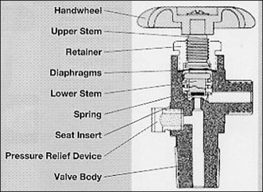
Diaphragm Valve - This valve uses a two piece stem separated by non-perforated diaphragms. These diaphragms prevent leakage along the valve stem. The lower part of the stem is encased in a spring, which forces the stem away from the seat whent eh valve is opened. The upper stem is threaded into the diaphragm retainer nut. When the handwheel is rotated to the closed position, the upper stem pushes on the diaphragms, which deflect downward, forcing the lower stem against the valve seat. Advantages of this type of valve are that they provide superior leak integrity and have no threads or lubricants in the gas stream to generate particles or contaminants. This type of valve is required for mos
Compressed gas cylinders shall have a pressure relief device installed to prevent the rupture of a normally pressurized cylinder when inadvertently exposed to fire of high temperatures. There are four basic types of pressure relief devices:
Combination Ruture Disks/Fusible Plug Devices - A rupture disk backed by a fusible plug. In the event of a fire, the fusible metal melts and cylinder overpressure is relieved by the bursting of the disk. The burst pressure of the disk and the melting point of the plug will be marked with the ratings. Medical grade gas cylinders typically have this type of pressure relief device.
Pressure Relief Valves - A spring-loaded valve opens when the cylinder pressure exceeds the pressure setting of the spring to discharge contents. Once the cylinder pressure decreases to the valve"s pressure setting, the valve will normally reseat without leakage.
We will explain compressed gas cylinder Safety guidelines in the term of identification, storage, handling, hazards, precaution and use of industrial compressed gas cylinders.
Argon, oxygen, acetylene, gases are compressed under high pressure and can be stored inside the cylinder for easy transportation and storage at working site.
Cylinders shall not be subjected to contact with direct flame, electric arc, molten metal, and other sources of heat, corrosive material or corrosive environment.
Cylinder : A pressure vessel designed for absolute pressures higher than 276 kPa and having a circular cross-section. It does not include a portable tank, multiunit tank car tank, cargo tank, or tank car. (Source: NFPA 55-2013, 3.3.29)
All cylinders that are received for use on site shall be colour coded on the shoulder of the Cylinder (curved part). The colour coding is intended to identify the properties of the gas in the cylinder. A number of industrial gases have been assigned a specific colour.
The colour coding described only applies to the shoulder, or curved part, at the top of the cylinder and is used to identify the properties of the gas in the cylinder.
All gas cylinders are required to be labelled to indicate the contents of the cylinder. Below is an example of a typical label, with an explanation of the various items that are to be displayed. It must always be remembered that the label is the means of identifying the contents of the cylinder. The colour of the cylinder is only a guide.
A suitable area dedicated for the storage of industrial gas cylinders shall be identified and provided for the storage of industrial gas cylinders. All cylinders shall be secured in an upright position and secured with the protective caps at all times in designated cylinder storage areas. All cylinders shall be labelled, marked and stored in accordance with their contents.
A suitable location within the site shall be established for the storage of gas cylinders in accordance to the following guidelines:An area where the cylinders has minimal exposure to excessive temperature, physical damage or tempering. Compressed gas cylinders shall not be exposed to direct temperatures exceeding 38o
The storage area shall be enough to contain the projected quantity of compressed gas cylinders that may be stored on site on any given time and to allow segregation distances between incompatible gases.
2) Construction LayoutCompressed gas cylinders storage area shall be delimited with such materials as chain links, fence or open block for the full height and width of the opening. Materials used to construct the storage area shall be non-combustible.
Cylinders shall not be placed directly onto the ground where they can be exposed to conditions which could cause corrosion on the base of the cylinders. They shall be placed on a slightly elevated and smooth surface, such as concrete flooring.
All cylinders shall be stored upright and restrained from toppling (e.g. secured at two levels with chain links, ropes) and shall not be propped against a wall or bench.
Full cylinders shall be kept separated from empty cylinders and sign posted to indicate ‘Full Cylinders’, ‘Empty Cylinders’. A partition shall be established in the storage area for this purpose.
Oxygen cylinders shall be stored separately (minimum of 6 meters or twenty feet) from all other sources of combustible gas, or by means of a non-combustible barrier at least five feet (two meters) high having a fire-resistant rating of at least one-half hour.
Cylinders of the same type shall be placed together. Incompatible gases shall be either separated by a distance of 6 meters or by means of a non-combustible barrier at least 2 (two) meters high having a fire-resistant rating of at least one-half hour. All empty cylinders shall be stored separately from all other cylinders.
Cylinders shall be placed in a manner that they do not become part of an electrical circuit and shall be kept away from piping systems and layout / cutting tables that may be used for grounding electrical circuits.
4) Oil, grease and other contaminantsOil or grease ignites violently in the presence of high pressure oxygen. Cylinders and fittings shall be kept clear from all sources of contamination such as oil barrels, cranes, drive belts etc.
Suspended work platform / basket shall not be used to lift compressed gas cylinders. Lifting of cylinders by direct slinging or lifting it off its valve protection collar is strictly prohibited.
1) Care of Compressed Gas Cylinderin useLoose dirt shall be cleared by ‘sniffing’ some gas to the atmosphere (opened slowly and then closed immediately) before connecting the regulators to the valve. This shall be
The standard key issued by the supplier for the cylinders shall be used. The leverage of keys shall not be increased and badly worn keys shall be removed.
When oxygen or fuel cylinders are connected to manifolds or headers, the manifolds shall be of a proper design with one or more pressure regulators, pressure relief devices and anti-flashback arrestors.
When compressed gas is supplied to process equipment from cylinders, the proper risk assessment shall be carried out. If the result of risk assessment requires, pressure relief devices shall be installed between the equipment and regulator(s) of the cylinder(s).
A typical oxy-fuel setup is shown in below figure. Flashback arrestors and check valves shall be installed on all oxygen and acetylene cutting gear. The flashback arrestor shall be installed at the regulator end and the check valve at the cutting torch end of each hose while in operation.
The following precautions shall be taken when using hoses connected to compressed gas cylinders;Only hoses that of a good quality and fit for the task shall be purchased. Substandard quality hoses crack and leak over a certain period of time.
No one except the owner or a person approved by the owner shall refill a compressed gas cylinder. All refill operations shall take place at the supplier / manufacturer location and shall not be carried out in the project site.
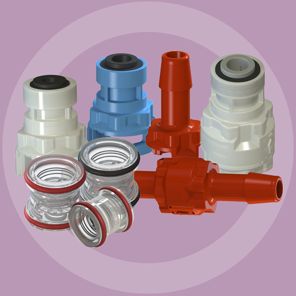
Assembling and maintaining a sample cylinder is easy. Just screw in the valves and use, right? Well getting the results you want consistently throughout the life of the sample cylinder requires a little more thought. Let"s discuss.
At SilcoTek we coat thousands of sample cylinders and valves a year with our inert CVD coatings. We know that for the customer to get the most out of their sample system, they not only need a high durability inert coating. Customers also need to understand that proper component selection, careful assembly, and periodic maintenance of sample cylinders can mean the difference between getting reliable results efficiently and disaster. Nobody wants a sample cylinder failure and they don"t want to keep taking samples because of test failures. That"s why taking a few simple steps before and after use make all the difference.
Do you need a constant pressure or constant volume sample cylinder? If you"re concerned about the phase change of the sample liquid, you may want to consider using a constant pressure sample cylinder. They"re more expensive, but you"re assured of measuring the process fluid under the right conditions.
Do you need a dip tube? A dip (or outage tube) are used to preserve some vapor space above liquefied gases. The dip tube allows only partial filling of the sample cylinder so the remaining vapor space can take up expansion of the liquid when the sample cylinder is exposed to higher temperatures. That helps to maintain cylinder pressure and avoid over pressurizing the sample cylinder. Here"s a good explanation on how to calculate the desired vapor space in the sample cylinder from Tom Bloom at Restek® Corp.
Dip tube length = % outage x cylinder length, i.e. a 50% outage on a 10in sample cylinder (.5x10) equals a dip tube length of 5in. (note this is an approximate calculation, consult the sample cylinder manufacturer for recommended length for their specific sample cylinder).
Select for the right pressure and environment. Select valve and sample cylinders that are pressure rated to exceed the expected pressure of the sample stream. Do not exceed the rated pressure of the cylinder or valve. Note that most cylinders are rated at an ambient temperature of around 100°c. If the sample environment exceeds the rated temperature contact the sample cylinder and valve manufacturer to be sure the cylinder and valve pressure capabilities will not be exceeded.
Need help finding the right coated sample cylinder or valve? You can find manufacturers that offer inert coated sample cylinders, valves, fittings, filters and regulators on our Buy Coated Products Page.
Do you need a ball valve or needle valve? Do you need fine control of the sample cylinder flow? Go with the needle valve. Does the valve have a burst disk to prevent sample cylinder failure. How durable is the valve? Will the valve be "cranked closed" in the field with a wrench? That will surely ruin the seat, so consider using a high durability sample cylinder valve with design features that prevent over tightening.
There are many high quality sample cylinder valve manufacturers out there. It"s a good idea to look within your field of use to find what combination of cylinders and valves work for your application. Consult others in your field and trade papers to get recommendations.
Be sure to coat the filter and sample cylinder with SilcoNert® or Dursan® to prevent active sites in the filter from adsorbing or reacting with the sample stream. For example sulfur is readily adsorbed by an uncoated sample cylinder when briefly exposed to the flow path, drastically affecting sample storage.
Inspect sample cylinder and valve for damage, especially on the threads. Check for burrs, gouges or nicks, crossed thread damage, galling damage and damage to the valve seat. If you"re using a relief valve, be sure there is no sign of damage to the relief valve or burst disk. Repair any damage and thoroughly clean threads before assembly. Inspect the inside shoulder of the sample cylinder for corrosion and particulate matter.
Clean the sample cylinder and valve before assembly. Clean for oxygen service or better, if using for analytical or sampling for sulfur or other reactive gases. Be sure the solvent used for cleaning will not leave a residue. Here are some tips for cleaning SilcoTek® coated sample cylinders and valves:
After cleaning apply PTFE tape to valve threads. To assure a leak tight seal, wrap the threads 3 times with a high quality PTFE tape. Leave the first threads exposed to assure positive thread engagement.
Tighten valves using a torque wrench. Torque to manufacturers specifications (usually a maximum of 8 to 10 ft-lbs). Threads should engage another 2-3 turns. Clamp cylinder assembly prior to torquing valves to facilitate the assembly process. Protect the cylinder from damage, scratches or gouging. Gouging the cylinder may compromise the pressure rating of the sample cylinder.
Develop a sample cylinder inspection plan and keep an inspection calendar to be sure sample cylinders and valves are periodically inspected. Inspection tips include:
For SilcoNert and Dursan coated cylinders, layer appearance and surface finish can vary from lot to lot. Small variations in surface thickness (measured in angstroms) can impact layer appearance. The surface finish should be bright and free of defects, but original surface condition can have a major impact on final surface quality.
If both mating parts must be coated, then SilcoTek recommends using anti Seize compounds made from Silver, Moly or Nickel: For sample cylinder applications refer to the instructions pertaining to the use of Teflon tape on the valve NPT prior to installation. Want to learn more about thread galling? Here"s a thorough article on galling from Machine Design.
Under normal use, your treated items should deliver outstanding performance for years to come. However; sample cylinder effective lifetime is dependent on the severity of the environment. Factors that can impede performance are:
Motherwell Tank Protection (MTP) manufacture breather valves, pressure vacuum relief valves, emergency relief vents, free vents, Gauge hatchesand level gauges. Supplying industries which include Oil & Gas, Petrochemical, food, water and Biogas
Motherwell Tank Protection, MTP, design and manufacture pressure vacuum relief valves, free vents,gauge hatchand level gauges. All products are designed and manufactured out of our custom built factory based in St Helen’s, UK. We are accredited by the (BSI) British Standards Institute the UK’s national standards organization that produces standards and information on products that promote and share best practice, and also numerous other accreditation’s. We have provided and supplied products to the oil and gas industry worldwide.
Our industry experience and expertise has allowed Motherwell Tank Protection to produce a range of high quality products such as pressure vacuum relief valves, Emergency Relief Vents, Liquid Level Gauges, Gauge hatches and many more. The whole manufacturing procedure is completed by the onsite Tank Fittings Department, resulting in innovative, safe yet cost effective products.
We can trace our manufacturing back to the year 1859 when the Bold Iron Works was established by William Neill & Son Ltd in St Helen’s, England. The company specialise in equipment for Chemical Factories and later for Oil Storage Installations and Oil Refineries. Under the name of Neill-Varec, the company manufactured tank level measuring devices, pressure relief valves and other tank instruments and fittings. The Company later joined the Capper-Neill Group before becoming a member of the Motherwell Bridge Group of Companies in 1984 it was subsequently the subject of a management buyout in 2003. Today, the company is today a wholly owned subsidiary of Motherwell Tank Holdings and specialists in storage tank fittings for the Bulk liquid storage tanks
As well as this, due to aircraft flying where the outside air temperature is extremely cold, this temperature variation affects the pressure the fuel tank is put under, making a pressure relief valve an essential part of any aircraft....

DOT Classified for recovery, recycling, service and reclaim. Liquid and vapor valves (Y valve or separate valve configurations) are installed in all cylinders. Painted yellow/gray per ARI guidelines. Float switches have 3-pin Brad Harrison connectors. Caution: Never overfill cylinders. Maximum refrigerant capacity is limited to 80% of the water capacity of the cylinder in lbs. (see table above). DOT requires cylinders to be retested every five years. Some recovery equipment uses weight scales to cut off refrigerant fill at 80% of capacity. Be sure cylinder tare weight is correct for this type of equipment. DOT Classification Example: 4BA400: 400 psi working pressure; 800 psi test pressure (double the working pressure); 1,600 psi minimum burst pressure (double the test pressure). Pressure relief/safety valve is set to release at between 75-100% of the test pressure. For example, in the 4BA400 tanks which have a 800 psi test pressure, the relief valve opens at between 600 psi and 800 psi.


 8613371530291