
danfoss ps40 safety valve supplier

If you are looking for Danfoss USA Product Store and catalog - which enables you to purchase our products - then please select the USA Product Store button.

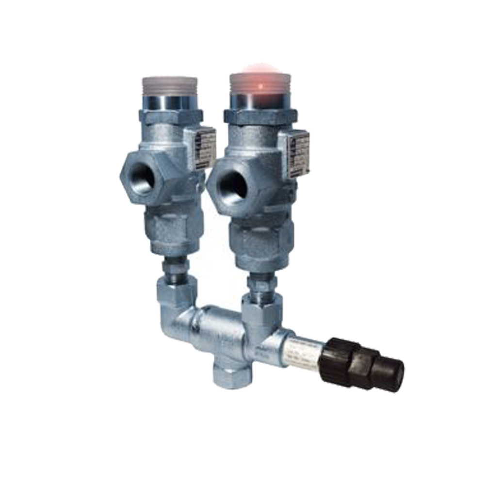
With the SFA 10 and DSV 10 change-over valve, Danfoss is widening its range of highly reliable safety valves designed to industrial standards. The new safety valves with their lower capacity and higher pressure range up to 65 bar provide more flexibility in system design. The SFA 10 can now be used in C02 applications on the low-pressure site as well as in low-charge ammonia systems. Furthermore, the spring housing is designed for reliability, increased lifetime, and to have no sudden reliefs below set pressure.

If you are looking for Danfoss USA Product Store and catalog - which enables you to purchase our products - then please select the USA Product Store button.
Pressure setting [bar]: 40, Connection type: G, Inlet connection size [in]: 3/4, Outlet connection size [in]: 1, Pressure certificate: Danfoss certificate included
Danfoss proportional valves, motorized control valves, balancing valves, ball valves, thermostatic valves, solenoid valves, and expansion valves—among others.
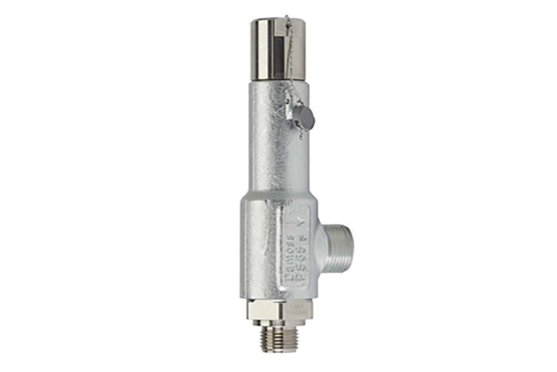
The Danfoss SFVL safety valves are back-pressure dependent pressure relief valves. These are designed for protection of vessels and other components against excessive pressure. These valves are recommended as an external and internal safety relief valve in refrigeration plants. These valves are manufactured according to strict quality demands and safety requirements for refrigeration installations, as specified in many markets and comply with ASHRAE Addendum15C-2000. These valves are manufactured in accordance with the ASME Quality Control Procedures and stamped with the UV symbol. They are certified by the United States National Board of Boiler & Pressure Vessel Inspectors and are stamped with the NB symbol.
The SFVL safety valves are backpressure dependent pressure relief valves. These are designed for protection of vessels and other components against excessive pressure. These valves are recommended as an external and internal safety relief valve in refrigeration plants.
These valves are manufactured according to strict quality demands and safety requirements for refrigeration installations, as specifi ed in many markets and comply with ASHRAE Addendum15C-2000. These valves are manufactured in accordance with the ASME Quality Control Procedures and stamped with the UV symbol. They are certifi ed by the United States National Board of Boiler & Pressure Vessel Inspectors and are stamped with the NB symbol
All relief valves come with an installation tag and cable wire. Each valve’s identifi cation tag has information regarding the catalogue number, month and year of manufacture, set pressure, inlet pipe size and capacity for AIR in units of SCFM. The tag is fastened with drive rivets for security.
Relief valves are subject to 100% factory testing through three separate test sequences to verify quality and set pressure before being factory sealed for security.

At Mittal Chambers, Secunderabad, Telangana, “Anvik Industrial Controls” is an entity that is instrumental in the business of wholesaling and trading optimum quality products. Since 1999, we are working as a partnership based entity, engrossed in shipping a top-notch quality spectrum of Brazed Plate Heat Exchanger, Industrial Control Valve, Pressure Switch, Solenoid Valve, Oil Separator, Filter Dryer, Strainer Housing Ammonia and many more. By preserving an enthusiastic approach towards quality, our business has been able to undergo in the competitive industries. Moreover to this, our knowledgeable professionals who are devoted to their work are assisting us in every sphere whether its logistics, quality testing or packaging.

PageIntroduction................................................................................................................................... 3General information about CO2 .................................................................................................... 3Design pressure...................................................................................................................... 3Material compatibility .............................................................................................................. 4Water in CO2 systems ............................................................................................................. 5Safety valves in CO2 systems ................................................................................................. 7Capacity.................................................................................................................................. 7Components for CO2 .................................................................................................................... 8Coils for solenoid valves ............................................................................................................... 9Pressure transmitters ................................................................................................................. 10Filter Driers ................................................................................................................................. 11Ordering ..................................................................................................................................... 12Delivery....................................................................................................................................... 19
The objective of this application guide isto provide an overview of which DanfossIndustrial Refrigeration products are suitablefor use in CO2 applications.
For further background information aboutCO2 as a refrigerant, please refer to theDanfoss article "CO2 Refrigerant for IndustrialRefrigeration" (literature number RZ0ZR).
Today, Danfoss is offering a broad programmeof industrial products applicable for CO2,however this is dependent on demandsregarding the design pressure. The tableon page 8 lists the components which aresuitable for CO2 applications together with themaximum working pressure limits.
There are a number of important factors to betaken into consideration when determining thedesign pressure.1. Pressure during operation:The pressure during operation isdependent on actual system design(single stage, cascade system or CO2brine system) and the load variation.2. Pressure during stand still:The pressure during stand still can bevery high and this has to be taken intoconsideration: A small separate refrigeration systemcan be used to keep the liquidtemperature at a level, where thesaturated pressure is lower thanthe design pressure Designing the system with an expansionvessel of a size that prevents thepressure from exceeding the designpressure. Designing the plant so that it canwithstand the saturated pressure at thedesign temperature (approx. 80 bar)From Danfoss experience, it would appearthat the most common solution for industrialrefrigeration applications is to use a smallseparate refrigeration system to limit thetemperature of the liquid CO2.
3. Pressure tolerances for safety valves(10 15 %)Safety valves require a certain pressuredifference (difference between set pressureand reseating pressure) to ensure that thevalve is closed properly.Normally the closing tolerance is 10%of the set pressure. Additionally, it is goodpractice to add 3-5% to the closingtolerance, to take care of any pressurevariations / peaks.Note:In the IoR - Code of Practice issued bythe Institute of Refrigeration in London, theabove mentioned tolerance is stated to be20%4. Temperature / pressure requrements fordefrostingDepending on the actual design, differentways of defrosting can be applied (natural,water, electrical or CO2 hot gas defrosting).The CO2 hot gas defrosting is the mostefficient, especially at low temperatures,but it also has the highest pressuredemand. With a design pressure of PS=50bar, it is possible to reach a defrostingtemperature of approx. 9-10C. Thesaturated pressure at 9C is 43.9 bar g. Byadding 10% for the safety valves andapprox. 5% for pressure peaks, therequirement is for pressure PS ~ 50 bar g.There is not one common method to performdefrosting. All methods, as described above,are used, depending on the system, but alsoon the availability of suitable compressors andother components.
By charging lubricant (oil) to the compressor.The acceptable amount of water in CO2systems is much lower than in systemswith other common refrigerants. If the watercontent exceeds the dew-point, and thetemperature is below 0C, the water willfreeze, creating a risk of problems withequipment in the system e.g. blockingcontrol valves.The water can very easily be removed bymounting a drier in the system.
When charging CO2, there are differentgrades of CO2, some of which allowrelatively high amounts of water. CO2 is treated as a very safe refrigerant,and is therefore handled without followingthe normal safety requirements. If a systemis opened up, air can penetrate into it, andthe moisture can condense inside the tubes.If the system is not evacuated properly,some water may well be retained.
An indication of water content can be obtainedby using a Danfoss SGN sight glass.- A dry system is shown with a greenindicator- A wet system is shown with a yellowindicatorWater/moisture content values for theseconditions are shown in fig. 3
Due to the thermodynamic properties of CO2,in particular the triple point, which is locatedat much higher pressure than for all othercommon refrigerants, the formation of solidCO2 can occur.If a safety valve is mounted in a CO2 systemat e.g. 50 bar, the pressure in the downstream(outlet) line from the safety valve will pass thetriple point at 5.2 bar.Below the triple point, CO2 will change from amixture of liquid and vapour into a mixture ofsolid and vapour.The formation of solid CO2 in the downstreamline can, in the worst case, block this line.
The most effective solution to this problem isto mount the safety valve without an outletline, thus blowing directly into the atmosphere.The phase change of the CO2 does not takeplace directly in the valve, but just after thevalve, and in this case in the atmosphere.If safety valves or any other safety devices,have to be mounted in liquid lines, they mustnever blow to the atmosphere or any otherplaces where the backpressure is below 5.2bar.If the back-pressure is below the triple point (5.2bar) a very high fraction of the CO2 will be solid.
Pressure Equipment Directive (PED)The Industrial Refrigeration valves areapproved in accordance with the Europeanstandards specified in the Pressure EquipmentDirective and are CE marked.
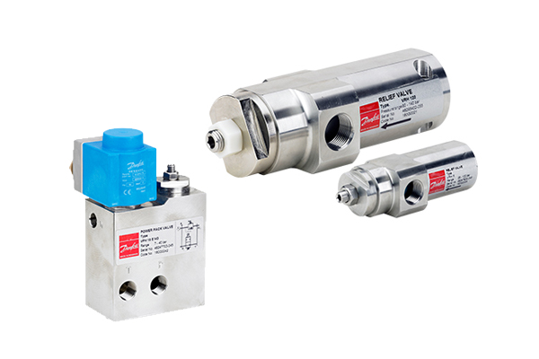
Danfoss industrial refrigerationhigh pressure componentsModulating liquid level regulatorsMain Valves, Solenoid ValvesPilot Valves for PM Main ValvesMotor Regulating ValvesMotor Expansion ValvesFloat ValvesStop ValvesRegulating ValvesStop Check ValvesGas Powered Stop ValveSafety Valves and Change Over Valves
In connection with the CE approval of thesevalves, Danfoss has implemented productmodifications and approved them for themaximum pressure. The products aresubject to specific testing and marking,but all of them are CE approved. Danfoss A/S (RC-CM / MWA), 06 - 2003
Due to the high pressure difference betweenthe condenser and evaporator, the MaximumOpening Pressure Differential (MOPD)demand for the solenoid valve in someapplications may exceed the standard coilcapabilities.
If the MOPD demands are beyond thecapability of the 20 W coil program or a d.c.supply is used, Danfoss has developed a newcoil concept, Power Electronic. With this newprogram the MOPD of the solenoid valve canbe increased up to 50 bar.
AKS 3000 is a series of absolute transmitterswith high-level signal conditioned currentoutput, developed to meet demands in A/C andrefrigeration.AKS 3000 utilises the proved piezoresistivemeasuring principle, which has been used fordecades in Danfoss pressure transmitters.
The following list details the most commonlyused Danfoss refrigeration components forCO2 applications. Components with alternativetypes of connections and dimensions can besupplied on request.


 8613371530291