
dcs rotisserie safety valve free sample
Fits DCS Models: 27, 27 series, 27A-BQRSS, 27A-BQSSN, 27D, 27FS-BQFN, 36A-BQSSN, 48A-BQSSN, BG27-BQN, BG27-BQRL, BG27BQL, BG27BQRN, BG36-BQARL, BG36-BQARN, BG48-BQARL, BG48-BQARN, BG48-BQRL, BG48-BQRN, BGA27-BQ, BGA27-BQL, BGA27-BQN, BGA27-BQR BGA27-BQRL, BGA27-BQRN, BGA36-BQAR, BGA36-BQARL, BGA36-BQARN, BGA48-BQR, BGB30-BQR, BGB30-BQRL, BGB30-BQRN, BGB36-BQARL, BGB48-BQARL, BGB48-BQARN, BGB48-BQRL, BGB48-BQRN, BQA27BQRL, DC27D-8QRN, DCS27-BQ, DCS27-BQR, DCS27-BQRS, DCS27-BQS DCS27A-BQ, DCS27A-BQR, DCS27D-BQL, DCS27D-BQRL, DCS27D-BQRN, DCS27D-BQRS, DCS27F-BQL, DCS27F-BQN, DCS27F-BQRL, DCS27F-BQRN, DCS27FS-BQ, DCS27FS-BQR, DCS36-BQAR, DCS36-BQARN DCS36-BQSL, DCS36A-BQA, DCS36A-BQARN, DCS36A-BQRN, DCS36B-BQAR, DCS36D-BQARN, DCS36D-BQRN, DCS36DS-BQA, DCS36DS-BQAR, DCS36DS-BQR, DCS36E-BQARL, DCS36E-BQARN, DCS48-BQARN, DCS48-BQRN, DCS48A-BQ, DCS48A-BQAR, DCS48A-BQARN, DCS48A-BQARS, DCS48A-BQR, DCS48A-BQRN, DCS48D-BQRN, DCS48DS-BQA, DCS48DS-BQAR, DCS48DS-BQR, DCS48E-BQARL, DCS48E-BQRL, DCS48E-BQRN, DCSE30BQR, DCSE30BQRSR, DCSE36BQAR, DCSE36BQR, DCSE48BQAR, DCSE48BQR, EDV27-BQ, EDV27-BQR, EDV27-BQRN, EDV36-BQA, EDV36-BQAR, EDV36-BQARN, FG27D-BQRCL, PC-2600, PC-26001, PC-2600L, PC-2600N, PCA-2600L, PCA-2600N
To ensure you choose the correct replacement part for your DCS grill you will need to know the model of your bbq grill. If you are unsure please email us and or call us we will be able to verify you will be ordering the correct part.
Verify your DCS model number by checking the CSA appliance tag on your grill to make sure you have the correct model number. Do not rely solely on the owners manual as these are frequently mixed up at retail stores when the grills are assembled. You"d be surprised at how many folks have the wrong owners manual.
.jpg)
Thank you for selecting this DCS Professional “BH1” Series Grill. Because of these appliances’ unique features we have developed this manual. It contains valuable information on how to properly install. operate and maintain your new appliance for years of safe and enjoyable cooking.
To help serve you better. please fill out and submit your Product Registration by visiting our website at www.dcsappliances.com and selecting “Customer Care” on the home page and then select “Product Registration”.
NOTE: Inspect the product to verify that there is no shipping damage. If any damage is detected. call the shipper and initiate a damage claim. DCS by Fisher & Paykel is not responsible for shipping damage.
“Overfilled” tanks can build up excess pressure. As a safety device. the tank pressure relief valve will vent propane gas vapor to relieve this excess pressure. This vapor is combustible and therefore can be ignited. To reduce this danger. you should take the following safety precautions:
2. If you own or use a spare tank. or have a disconnected tank. you should NEVER store it near or under the grill/cart unit or heat box. or near any other ignition or heat source. A metallic sticker with this warning is provided with the grill to re mind you. your family and all others who may use your BBQ grill of these safety precautions. Install this sticker close to your barbeque grill.
For personal safety. wear proper apparel. Loose fitting garments or sleeves should never be worn while using this appliance. Some synthetic fabrics are highly flammable and should not be worn while cooking. Only certain types of glass. heat-proof glass ceramic. earthenware. or other glazed utensils are suitable for grill use. These types of materials may break with sudden temperature changes. Use only on low or medium heat settings ac cording to the manufacturer’s directions.
Spiders and insects can nest in the grill burners. causing gas not to flow through the burner. The gas will flow from the front of the burner into the control panel. This is a very dangerous condition which can cause a fire to occur behind the valve panel. thereby damaging the grill components and making it unsafe to operate.
As high-performance gas appliance. your grill requires significant amounts of air to support the combustion process. Your grill is designed to take air in through the valve panel area. and send the exhaust products out through the exhaust gap at the rear of the hood. Using your grill in windy conditions can disrupt the proper flow of air though your grill. leading to reduced performance. or in certain severe cases. causing heat buildup in the valve panel area. This can lead to problems such as having the knobs melt. or burn hazards when the valve panel surfaces become too hot to touch.
During high wind conditions. it is best if you don’t use your grill. If you live in an area that is subject to frequent high winds. or a steady directional wind. then the installation of a suitable windbreak may be advised. If you have a grilling cart. it is best to position the unit so the prevailing wind blows into the valve panel. thus supporting the proper airflow. Winds hitting the back of the grill directly are the most likely to cause problems. although wind blowing along the exhaust gap in the rear can also be problematic.
Please note that damage to your grill resulting from use in windy conditions. such as melted knobs or igniter wires. or valve panel discoloration from heat build-up. are excluded from warranty coverage.
Clearances to Non-Combustible Construction*: A minimum of 3” clearance from the back of the grill to non-combustible construction is required for the purpose of allowing the lid to open fully. It is desirable to allow at least 6” rear and side clearance to non-combustible construction above the cooking surface for counter space. If you’ll be using the rotisserie option. the space is es sential for motor and skewer clearance. The grill can be placed directly adjacent to non-combustible construction below the cooking surface. (Fig. 03)
If the grill is to be placed into a combustible enclosure. an approved insulated jacket is necessary. Insulated jack ets are available from your dealer. Use only the DCS insulated jacket which has specifically been designed and tested for this purpose. Review the detail drawing shown (Fig. 05) and take into account the provisions shown for gas line hook-up clearance in the right rear corner. It is required that ventilation holes are provided in the enclo sure to eliminate the potential build-up of gas in the event of a gas leak. The supporting ledges or deck must be level and flat and strong enough to support the grill and insulated jacket. The counter should also be level.
An installer-supplied gas shut-off valve must be installed in an easily accessible location. All installer supplied parts must conform to local codes. or in the absence of local codes. with the National Electrical Code. ANSI/NFPA 70 or the Canadian Electrical Code. CSA C22.1. and the National Fuel Gas Code. ANSI Z223.1 or CSA-B149.1 Natural Gas Installation Code or CSA-B149.2 Propane Installation Code.
The appliance and its individual shut-off valve must be disconnected from the gas supply piping system during any pressure testing of that system at test pressures in excess of 1/2 PSIG (3.5 kPa.) The appliance must be isolat ed from the gas supply piping system by closing its individual manual shut-off valve during any pressure testing of the gas supply piping system at test pressures equal to or less than 1/2 PSIG (3.5 kPa.). The installation of this appliance must conform with local codes or. in the absence of local codes. with the National Fuel Gas Code. ANSI Z223.1/NFPA 54. Installation in Can ada must be in accordance with Natural Gas and Propane Installation Code.
TO HOOK-UP THE FITTINGS SUPPLIED WITH THE GRILL: Assemble as shown (Fig. 08). Use threading compound on male threads only. Do not use threading compound on the male end of the 1/2 NPT to 3/8 flare adapter. Use a second pipe wrench to hold the grill inlet pipe to avoid shifting any internal gas lines of the grill. Ensure that the regulator arrow points in the direction of gas flow towards the unit. away from the supply. Do not forget to place the installer-supplied gas valve in an accessible location.
Before connecting LP tank to regulator. check that all grill burners and side burners. smokers. and rotisserie valves are in the OFF position and open grill lid.
To connect the LP regulator/hose assembly to the tank/valve assembly. first make sure the main valve on the tank is completely closed. Although the flow of gas is stopped when the Type 1 system is disconnected as part of of its safety feature. you should always turn off the LP tank main valve (Fig. 09) after each use and during transport of the tank or unit. Insert the regulator inlet into the tank valve and turn to the black coupler clockwise until the coupler tightens up. Do not overtighten the coupler. Turn the main tank valve on and turn the burner control valves on the unit to the “HI” position for about 20 seconds to allow the air in the system to purge. Turn valves off and wait 5 minutes before attempting to light the burners.
To disconnect the coupler. first make sure the main tank valve is turned off. Grasp the coupler and turn counter clockwise. The inlet will then disengage. Remove the inlet from the tank valve opening if it has not already done so when it disengaged. Your local LP filling station should be equipped with the proper equipment to fill your tank.
LP TANK REQUIREMENTS: A dented or rusty LP tank may be hazardous and should be checked by your LP supplier. The cylinder that is used must have a collar to protect the cylinder valve. Never use a cylinder with a damaged valve. Always check for leaks after every LP tank change. The LP gas cylinder must be constructed and marked in accordance with the specifications for LP gas cylinders of the U.S. Department of Transportation (DOT or CAN/CSA-B339) and de signed for use with a Type 1 system only. Do not change the regulator/hose assembly from that supplied with the unit or attempt to use a Type 1 equipped regulator/hose assembly with a standard 510 POL tank/valve assembly.
The cylinder must be provided with a shut-off valve terminating in an LP gas supply cylinder valve outlet speci fied. as applicable. for connection Type 1. If the appliance is stored indoors. the cylinder must be disconnected and removed from the appliance. Cylinders must be stored outdoors in a well-ventilated area out of the reach of children.
If you intend to operate your Built-in grill on LP gas utilizing a 20v lb Type 1 cylinder. then the Built-in LP tank restraint must be installed prior to initial use of the grill. If you do not have one please contact DCS Customer Care at (888) 936-7872 for information on obtaining one.
Before Testing: Do not smoke while leak testing. Extinguish all open flames. Never leak test with an open flame.Make a soap solution of one part liquid detergent and one part water. You will need a spray bottle. brush. or rag to apply the solution to the fittings. For LP units. check with a full cylinder. The valve panel must be removed to check the valves and fittings. Remove the knobs and the safety valve knob. then remove the 2 screws which fasten the valve panel to the unit (you will need a Philips screw driver for this). Pull the valve panel outward and unplug the wires from the ignition module. In the back of the unit remove the screws which hold the service panel in place.
To Test: Make sure all control valves are in the “OFF” position. Turn the gas supply “ON”. Check all connections from the supply line. or LP cylinder up to and including the manifold pipe assembly. Apply the soap solution around the connection. valve. tubing and end of the manifold. Avoid getting the soap solution on or in the valve switches.
Soap bubbles will appear where a leak is present. If a leak is present. immediately turn off gas supply. tighten any leaking connections. turn gas on. and recheck. Check all the gas connections at the base of the control valves where they screw into the manifold pipe.
To check rotisserie burner and safety valve the burner must be lit. then leak test the connections located behind the service panel. If you cannot stop a gas leak turn off the gas supply and call your local gas utility. or the dealer you purchased the appliance from. Only those parts recommended by the manufacturer should be used on the grill. Substitution can void the warranty.
Check all gas supply fittings for leaks before each use. Keep a spray bottle of soapy water near the gas supply shut-off valve. Spray all the fittings. Bubbles indicate leaks (Fig. 16 & 17).
GRILL BURNER AIR ADJUSTMENT: Each grill burner is tested and adjusted at the factory prior to shipment; however. variations in the local gas supply or a conversion from one gas to another may make it necessary to adjust the burners. The flames of the burners (except the rotisserie burner) should be visually checked and compared to that of the drawing in Fig.18.
LOW FLAME SETTING ADJUSTMENT: The valves on the grill feature an adjustable low setting. Due to fluctuations in gas pressure. heating value or gas conversion. you may feel it necessary to increase or decrease gas flow in the low position. We do not recommend adjusting the infrared rotisserie burner.
4. While holding the valve shaft with pliers. insert a thin. flat tipped screwdriver into the shaft and while viewing the burner adjust to a minimum stable flame (Fig. 19).
NOTE: If any of the listed items are missing. contact DCS at (888) 936-7872. Please be prepared with your Model #. Serial # and description of item(s) that are missing.
NOTE: Improper lighting procedures can cause the LP tank flow control to activate. resulting in reduced heat output. If this is sus pected. to reset flow control. shut off all burner controls and LP cylinder valve. wait 30 seconds. then turn LP cylinder valve on extremely slowly. wait five (5) seconds and push and hold the ignition button and turn burner valve on to “SEAR”.
Note: The temperature gauge only indicates air temperature inside the grill. For food safety and optimal cooking performance. use a meat probe to check the temperature of meat while cooking and to ensure desired internal temperatures are reached.
The smoker system on each grill consists of a stainless steel slide out tray which is positioned above a 3. 00 Btu/hr or 3.7 MJ/h burner. The burner is controlled by a precision brass valve which is capable of being turned down to very low heat levels. The system may be used alone for low temperature roasting and smoking or in conjunction with any combination of other burn ers. When using the smoker system in conjunction with the optional infrared rotisserie burner. you’ll find it helpful to use the low setting of the smoker burner to minimize the heat rising up to the rotisserie basting pan. Stagger ing the meat away from the smoker burner also helps.
TO LIGHT THE SMOKER BURNER: Open the lid and remove the smoker tray. Locate the burner visually by look ing through the cut-out in the valve panel. Push in the burner knob and turn to the “HI” position until the burner is lit or 4 seconds pass. If the burner doesn’t ignite. wait 5 minutes for any accumulated gas to dissipate. then try again. If the burner will not light after several attempts. wait 5 minutes. then match light using a paper book match through the cut-out in the valve panel.
The grill rotisserie system is designed to cook items from the back using infrared heat. The location of the burner allows the placement of the rotisserie basting pan (included) beneath the food to collect juices and drippings for basting and gravy. To flavor the contents of the basting pan. you can add herbs. onion. garlic. or spices. Hams are especially good with the addition of pineapple slices and brown sugar to the basting pan. The rotis serie burner is an infrared type which provides intense searing radiant heat. Preferred by chefs over other methods. this intense heat is magnificent for searing in the natural juices and nutrients found in quality cuts of meat.
Once lit. the rotisserie burner will reach cooking temperatures in about 1 minute. The orange/red glow will even out in about 5 minutes. The rotisserie motor is equipped with metal gears and is capable of turning up to a 50 lb. cut of meat or poultry. The rotisserie motor on the grills is secured down to a cast rotisserie block with two black screw- down knobs. The rotisserie block is in turn bolted to the right side panel. The rod for the rotisserie is assembled into the motor assembly by placing the pointed end into the motor. and resting the handle end on the support at the left side of the grill. With the rod pushed as far as possible into the motor. the round end of the rod should rest on the rollers.
Never have the grill burners (bottom burners) on during Rotisserie cooking. It will burn your meat and make it very dry. Use only one section at a time. grill or rotisserie.
The meat will cook more evenly while on the Rotisserie. For Poultry. tie wings and legs to the body using Dental floss or butcher string to prevent flopping around while turning. (Fig. 35)
TO LIGHT THE ROTISSERIE BURNER BEFORE COOKING: The location of the rotisserie burner makes it more susceptible to strong wind conditions. more so than the protected grill burners. For this reason you should avoid operating the rotisserie during windy conditions. As an added safety feature we’ve equipped the burner with an automatic safety valve which will not allow gas to flow to the rotisserie burner unless the following conditions are present with the knob on:
Engage the safety valve button and continue to hold until the burner is lit. Once lit. turn control knob to desired setting. If the burner does not light within 4 to 5 seconds. release the safety valve button and turn the control knob to “OFF” and wait 5 minutes before trying again.
MANUAL LIGHTING: To manually light the rotisserie. place a butane lighter near the tip of the thermocouple as shown in Fig. 38. Turn the control knob to “HI”. Hold the safety valve button in for about 4 to 5 seconds or until the burner remains lit. Once lit. turn control knob to desired setting. If the burner does not light within 4 or 5 seconds. release the safety valve button and turn the control knob to “OFF” and wait 5 min utes before trying again.
Electrical Grounding Instructions: This appliance (rotisserie motor) is equipped with a three-prong (grounding) plug for your protection against shock hazard and should be plugged directly into a properly grounded three-prong receptacle or a three-prong grounded extension cord rated for the power of the rotisserie motor and approved for outdoor use with a W-A marking. Do not cut or remove the grounding prong from this plug. Use only a ground fault interrupter (GFI) protected circuit.
The rotisserie motor must be electrically grounded in accordance with local codes or. in the absence of local codes. with the National Electrical Code. ANSI/NFPA 70. Keep the rotisserie motor electric cord away from the heated surfaces of the grill. When not in use. remove and store the motor in a dry location. To protect against electric shock. do not immerse the cord or plug in water or other liquid. Unplug rotisserie unit from the outlet when not in use and before cleaning. Allow the rotisserie to cool before putting on or taking off parts.
5. When you have finished using the rotisserie. turn off motor and turn the rotisserie knob to “OFF”. If you have fin ished using the appliance altogether. turn the main gas supply off too.
BEFORE CALLING FOR SERVICE: If the grill does not function properly. use the following checklist before contacting your dealer for service. You may save the cost of a service call. Troubleshooting is for general purposes only. If the problem persists and you feel you require service. contact your dealer or the nearest authorized agency to perform service. Only autho rized agencies can perform warranty service. Call DCS Customer Care at (888) 936-7872.
ROTISSERIE LIGHTS. BUT WILL NOT HOLD FLAME ONCE BUTTON IS RELEASED: 1. Continue holding safety valve button in depressed position until burner remains lit when released.
For warranty service. please contact your local service provider or DCS Customer Care at (888) 936-7872. Before you call. please have the following information ready:

SAVE THESE INSTRUCTIONS The models shown in this user guide may not be available in all markets and are subject to change at any time. For current details about model and specification availability in your country. please visit our website listed on the back cover or contact your DCS by Fisher & Paykel dealer.
Thank you for selecting this DCS Evolution Series Grill. This installation and user guide contains valuable information on how to properly install. operate and maintain your new appliance for years of safe and enjoyable cooking.
Please fill out and submit your Product Registration by visiting our website at www. dcsappliances.com and selecting “Support” on the home page and then selecting “Product Registration”. In addition. keep this guide handy. as it will help answer questions that may arise as you use your new appliance.
Inspect the product to verify that there is no shipping damage. If any damage is detected. call the shipper and initiate a damage claim. DCS by Fisher & Paykel is not responsible for shipping damage.
To reduce the risk of fire. electrical shock. injury to persons. or damage when using the appliance. follow the important safety instructions listed below:
Certain Liquid Propane dealers may fill liquid propane cylinders for use in the grill beyond cylinder filling capacity. This “overfilling” may create a dangerous condition. “Overfilled” tanks can build up excess pressure. As a safety device. the tank pressure relief valve will vent propane gas vapor to relieve this excess pressure. This vapor is combustible and therefore can be ignited.
Follow the installation instructions within this manual. Have your grill installed by a qualified installer. Have the installer show you where the gas supply shut-off valve is located so that you know where and how to shut off the gas to the grill. If the connections are not perfectly sealed. you can have a small leak and therefore a faint gas smell. Some leaks can only be found with the burner control in the “ON” position - this must be done by a qualified technician.
Clean and perform general maintenance on the grill twice a year. Watch for corrosion. cracks. or insect activity. Check the regulator. hoses. burner ports. air shutter. and venturi/valve section carefully. Always turn off gas at the source (tank or supply line) prior to inspecting parts.
As a high-performance gas appliance. your grill requires significant amounts of air to support the combustion process. Your grill is designed to take air in through the valve panel area. and send the exhaust products out through the exhaust gap at the rear of the hood. Using your grill in windy conditions can disrupt the proper flow of air though your grill. leading to reduced performance. or in certain severe cases. causing heat buildup in the valve panel area. This can lead to problems such as having the knobs melt. or burn hazards when the valve panel surfaces become too hot to touch.
Please note that damage to your grill resulting from use in windy conditions. such as melted knobs or igniter wires. or valve panel discoloration from heat build-up. are excluded from warranty coverage.
Clearances to non-combustible construction* A minimum of 3” (76mm) clearance from the back of the grill to non-combustible construction is required for the purpose of allowing the hood to open fully. It is desirable to allow at least 6” (153mm) rear and side clearance to non-combustible construction above the cooking surface for counter space. If you’ll be using the rotisserie option. the space is essential for motor and skewer clearance. The grill can be placed directly adjacent to non-combustible construction below the cooking surface (Fig. 02).
Insulated jackets are available from your dealer. Use only the DCS insulated jacket which has specifically been designed and tested for this purpose. Review the detail drawing shown (Fig. 06) and take into account the provisions shown for gas line hook-up clearance in the right rear corner.
A 18” (457mm) minimum clearance must be maintained under the counter top to combustible con struction. The clearance can be modified by a use of an insulated jacket. Insulated jackets can be purchased from our website. www.dcsappliances.com.
An installer-supplied gas shut-off valve must be installed in an easily accessible location. All installer supplied parts must conform to local codes. or in the absence of local codes. with the National Electrical Code. ANSI/NFPA 70 or the Canadian Electrical Code. CSA C22.1. and the National Fuel Gas Code. ANSI Z223.1 or CSA-B149.1 Natural Gas Installation Code or CSA-B149.2 Propane Installation Code.
Total gas consumption of the grill with all burners on HI BE1-48R - 118. 00 Btu/hr or 124.5 Mj/hr BE1-36R - 89. 00 Btu/hr or 93.3 Mj/hr The appliance and its individual shut-off valve must be disconnected from the gas supply piping system during any pressure testing of that system at test pressures in excess of 1/2 PSIG (3.5 kPa).
The appliance must be isolated from the gas supply piping system by closing its individual manual shut-off valve during any pressure testing of the gas supply piping system at test pressures equal to or less than 1/2 PSIG (3.5 kPa). The installation of this appliance must conform with local codes or. in the absence of local codes. with the National Fuel Gas Code. ANSI Z223.1/NFPA 54. Installation in Can ada must be in accordance with Natural Gas and Propane Installation Code. CSA B149.1. and/or Propane Storage and Handling Code. B149.2 and local codes.
To hook-up the fittings supplied with the grill Assemble as shown (Fig. 07). Use threading compound on male threads only. Use a second pipe wrench to hold the grill inlet pipe to avoid shifting any internal gas lines of the grill. Ensure that the regulator arrow points in the direction of gas flow towards the unit. away from the supply. Do not forget to place the installer-supplied gas valve in an accessible location.
To connect the LP regulator/hose assembly to the tank/valve assembly. first make sure the main valve on the tank is completely closed. Although the flow of gas is stopped when the Type 1 system is disconnected as part of its safety feature. you should always turn off the LP tank main valve (Fig. 08) after each use and during transport of the tank or unit. Insert the regulator inlet into the tank valve and turn to the black coupler clockwise until the coupler tightens up. Do not over tighten the coupler. Turn the main tank valve on and turn the burner control valves on the unit to the “HI” position for about 20 seconds to allow the air in the system to purge. Turn valves off and wait five minutes before attempting to ignite the burners.
To disconnect the coupler. first make sure the main tank valve is turned off. Grasp the coupler and turn counter clockwise. The inlet will then disengage. Remove the inlet from the tank valve opening if it has not already done so when it disengaged. Your local LP filling station should be equipped with the proper equipment to fill your tank.
LP tank requirements: A dented or rusty LP tank may be hazardous and should be checked by your LP supplier. The cylinder that is used must have a collar to protect the cylinder valve. Never use a cylinder with a damaged valve. Always check for leaks after every LP tank change. The LP gas cylinder must be constructed and marked in accordance with the specifications for LP gas cylinders of the U.S.
Department of Transportation (DOT or CAN/CSA-B339) and designed for use with a Type 1 system only. Do not change the regulator/hose assembly from that supplied with the unit or attempt to use a Type 1 equipped regulator/hose assembly with a standard 510 POL tank/valve assembly. The cylinder must be provided with a shut-off valve terminating in an LP gas supply cylinder valve outlet specified. as applicable. for connection Type 1. If the appliance is stored indoors. the cylinder must be disconnected and removed from the appliance. Cylinders must be stored outdoors in a well ventilated area out of the reach of children.
To Test Make sure all control valves are in the “OFF” position. Turn the gas supply “ON”. Check all connections from the supply line. or LP cylinder. Apply the soap solution around the connection. tubing and end of the manifold. Soap bubbles will appear where a leak is present. If a leak is present. immediately turn off gas supply. tighten any leaking connections. turn gas on. and recheck.
Check all gas supply fittings for leaks before each use. Keep a spray bottle of soapy water near the gas supply shut-off valve. Spray all the fittings. bubbles indicate leaks
Grill burner air adjustment Each grill burner is tested and adjusted at the factory prior to shipment; however. variations in the local gas supply or a conversion from one gas to another may make it necessary to adjust the burners. The flames of the burners (except the rotisserie burner) should be visually checked and compared to that of the drawing in Fig.14. Flames should be blue and stable with no yellow tips (LP units may have some yellow tipping). excessive noise or lifting. If any of these conditions exist. check if the air shutter or burner ports are blocked by dirt. debris. spider webs. etc. If cleaning the burner ports and air shutter does not improve performance. you can alter the air shutter adjustment. The amount of air which enters a burner is governed by a metal cup at the inlet of the burner called an air shutter. It is locked in place by a screw which must be loosened prior to lighting the burner for adjustment.
Low flame setting adjustment The valves on the grill feature an adjustable low setting. Due to fluctuations in gas pressure. heating value or gas conversion. you may feel it necessary to increase or decrease gas flow in the low position. We do not recommend adjusting the infrared rotisserie burner.
4 While holding the valve shaft with pliers. insert a thin. flat tipped screwdriver into the shaft and while viewing the burner adjust to a minimum stable flame.
Contact DCS at www.dcsappliances.com if any of the listed items are missing. Please be prepared with your Model #. Serial # and description of item(s) that are missing.
Do not use the rotisserie burner when the secondary cooking racks or trays are in place. Before using the rotisserie burner. ensure that these racks and trays are removed.
Note: the temperature gauge only indicates air temperature inside the grill. For food safety and optimal cooking performance. use a meat probe to check the temperature of meat while cooking and to ensure desired internal temperatures are reached.
General The grill rotisserie system is designed to cook items from the back using infrared heat. The location of the burner allows the placement of the secondary cooking tray beneath the food to collect juices and drippings for basting and gravy. To flavor the contents of the cooking tray. you can add herbs. onion. garlic. or spices. Hams are especially good with the addition of pineapple slices and brown sugar to the cooking tray. The rotisserie burner is an infrared type which provides intense searing radiant heat. Preferred by chefs over other methods. this intense heat is magnificent for searing in the meat’s natural juices and nutrient.
The rotisserie motor is equipped with metal gears and is capable of turning a cut of meat or poultry that weighs up to 50 lb. The rotisserie motor on the grills is secured down to a cast rotisserie block with two black screw down knobs. The rotisserie block is in turn bolted to the side panel. The rotisserie rod is assembled into the motor assembly by placing the pointed end into the motor. and resting the handle end on the support at the left side of the grill. With the rod pushed as far as possible into the motor. the round end of the rod should rest on the rollers.
Do not use the rotisserie burner when the secondary cooking racks or trays are in place. Before using the rotisserie burner. ensure that these racks and trays are removed.
Meat preparation Tie meat with butcher string or dental floss in three areas. Purchase a roast that is equally balanced from top to bottom in size to ensure meat will cook evenly while on the Rotisserie. For Poultry. tie wings and legs to the body using dental floss or butcher string to prevent flopping around while turning.
To light the rotisserie burner before cooking The location of the rotisserie burner makes it more susceptible to strong wind conditions. more so than the protected grill burners. For this reason you should avoid operating the rotisserie during windy conditions. As an added safety feature we’ve equipped the burner with an automatic safety valve which will not allow gas to flow to the rotisserie burner unless the following conditions are present with the knob on:
Push in and hold the selected burner knob for two seconds. Verify that the hot surface igniter is glowing. Turn the burner knob to “HI” position. Then press and hold the safety valve button in for 10 seconds or until the burner remains lit. Once lit. turn control knob to desired setting. If burner does not light. turn knob "OFF" and wait five minutes before trying again so any accumulated gas may dissipate.
Electrical Grounding Instructions: this appliance (rotisserie motor) is equipped with a three-prong (grounding) plug for your protection against shock hazard and should be plugged directly into a properly grounded three-prong receptacle or a three-prong grounded extension cord rated for the power of the rotisserie motor and approved for outdoor use with a W-A marking. Do not cut or remove the grounding prong from this plug. Use only a ground fault interrupter (GFI) protected circuit.
The rotisserie motor must be electrically grounded in accordance with local codes or. in the absence of local codes. with the National Electrical Code. ANSI/NFPA 70. Keep the rotisserie motor electric cord away from the heated surfaces of the grill. When not in use. remove and store the motor in a dry location. To protect against electric shock. do not immerse the cord or plug in water or other liquid. Unplug rotisserie unit from the outlet when not in use and before cleaning. Allow the rotisserie to cool before putting on or taking off parts.
Manual lighting To manually light the rotisserie. place a butane lighter near the tip of the thermocouple. Push in and turn the control knob to “HI”. Hold the safety valve button in for 10 seconds or until the burner remains lit. Once lit. turn control knob to desired setting. If the burner does not light. release the safety valve button and turn the control knob to “OFF” and wait 5 minutes before trying again.
The rotisserie rod can be stored in the tray located under the grill head. When storing the rotisserie rods. please use two hands to store it correctly and ensure it is locked into place. Please use two hands to remove the rod from its storage compartment. taking care to ensure it does not drop.
Storage unit The unit can be bolted onto either side of the grill. Please note. if you are using the rotisserie. the storage unit will need to be installed on the opposite side to where the motor sits. You can install up to two storage units on the grill. however. as the storage unit is attached at the same location as the rotisserie motor. installing two storage units will mean that the rotisserie motor cannot be installed.
Insulated jacket We recommend purchasing a DCS insulated jacket if installing your grill into a combustible enclosure. as it will reduce the risk of fire. property damage and personal injury. Please see the insulated jacket quick start guide for install instructions. use and care and further information.
Regulator and hose replacement The pressure regulator and hose assembly supplied with the unit must be used. If replacements are needed. contact customer care at www.dcsappliances.com. Do not use the grill if the odor of gas is present. If the unit is LP. screw the regulator into the tank and leak check the hose and regulator connections with a soap and water solution before operating the grill. Turn all knobs to “OFF” then turn on the gas supply. If LP. check that there is gas in the tank.
Before calling for service If the grill does not function properly. use the following checklist before contacting your dealer for service. You may save the cost of a service call. Troubleshooting is for general purposes only. If the problem persists and you feel you require service. contact your dealer or the nearest authorized agency to perform service. Only authorized agencies can perform warranty service. Contact DCS at www.dcsappliances.com
If after checking these points you still need assistance or parts. please refer to the Service & Warranty book for warranty details and your nearest Authorized Service Centre. Customer Care. or contact us through our website www.dcsappliances.com or email: [email protected]

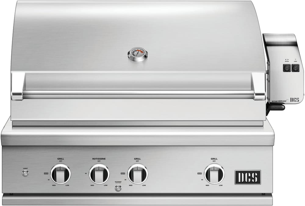
DCS grills are engineered for people who want to cook just like a professional chef in their own home. This 36-inch natural gas built-in grill features three 25,000 BTU U-shaped stainless steel burners that push an impressive total of 75,000 BTUs of cooking power. Each burner features a heat shield that directs heat upwards, maximizing grilling efficiency. DCS grills offer Ceramic Radiant Technology, which is a layer of ceramic rods placed between the burners and cooking grate. The rods provide intensely, yet even heat, ensuring the temperature is consistent across the entire grilling surface. This innovative feature allows you to sear meat to perfection anywhere on the cooking grid. This grill boasts a 638 square inch main cooking surface with durable, double-sided cast stainless steel cooking grids. One side has a gentle curve that supports and handles fish and vegetables. The other side of the grates accommodates steaks and other cuts of meat, capturing grease while creating perfect sear lines. DCS BH1 grills feature a wider range of cooking temperatures with valves that can be turned down to as low as 300 degrees at the grilling surface. The patented Grease Management system effectively channels grease and oil away from the flame while grilling, which greatly reduces flare-ups. The 14,000 BTU infrared rear burner functions perfectly for slow-roasting, and the included rotisserie kit can accommodate up to 50 lbs! The smoker tray is welded closed so you can add your favorite wine or beer into the tray. A dedicated 3,500 BTU smoker burner allows the wood chips to slowly smolder for more layers of flavor. The removable warming rack features a spacious 241 square inch, stainless steel warming area. The push and turn 9-volt battery ignition operates with the ease of an indoor range, and the 40-watt halogen Smart Beam BBQ grill light adds visibility while you grill. The temperature gauge allows you to control cooking temperatures. Every DCS grill is handcrafted and constructed entirely of heavy gauge, type 304 stainless steel.


 8613371530291