
define safety valve theory factory

The Supreme Court has reinforced the theory of the First Amendment as a "safety valve," reasoning that citizens who are free to to express displeasure against government through peaceful protest will be deterred from undertaking violent means. The boundary between what is peaceful and what is violent is not always clear. For example, in this 1965 photo, Alabama State College students participated in a non-violent protest for voter rights when deputies confronted them anyway, breaking up the gathering. (AP Photo/Perry Aycock, used with permission from the Associated Press)
Under the safety valve rationale, citizens are free to make statements concerning controversial societal issues to express their displeasure against government and its policies. In assuming this right, citizens will be deterred from undertaking violent means to draw attention to their causes.
The First Amendment, in safeguarding freedom of speech, religion, peaceable assembly, and a right to petition government, embodies the safety valve theory.
These and other decisions rest on the idea that it is better to allow members of the public to judge ideas for themselves and act accordingly than to have the government act as a censure. The Court has even shown support in cases concerning obscenity or speech that incites violent action. The safety valve theory suggests that such a policy is more likely to lead to civil peace than to civil disruption.
Justice Louis D. Brandeis recognized the potential for the First Amendment to serve as a safety valve in his concurring opinion in Whitney v. California (1927) when he wrote: “fear breeds repression; . . . repression breeds hate; . . . hate menaces stable government; . . . the path of safety lies in the opportunity to discuss freely supposed grievances and proposed remedies; and the fitting remedy for evil counsels is good ones.”

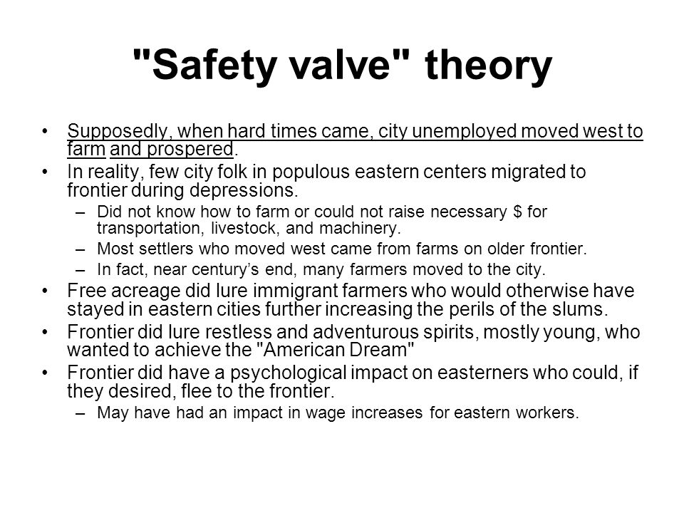
The safety valve theory was a theory about how to deal with unemployment which gave rise to the Homestead Act of 1862 in the United States. Given the concentration of immigrants (and population) on the Eastern coast, it was hypothesized that making free land available in the West would relieve the pressure for employment in the East. By analogy with steam pressure (= the need for work), the enactment of a free land law, it was believed, would act as a safety valve. This theory meant that if the East started filling up with immigrants, they could always go West until they reached a point where they could not move any farther.
A distinction has to be made between (1) the safety valve theory as an ideal and (2) the safety valve theory as embodied in the Homestead Act of 1862.
There is a dispute whether and to what extent the Homestead Act did or did not succeed as a safety valve in ameliorating the problem of unemployment in the East.

Historian Frederick Jackson Turner put forward his Frontier Thesis about American history in 1893. For many years it was an influential theory about the importance of the frontier in US history.
The difference was significant. The safety valve theory held that having open lands in the West was important to draw off excess, unnecessary people...
One of the most critical automatic safety devices in a pressure system is the pressure safety valve. The primary purpose of a pressure safety valve is the protection of life, property and environment during an over-pressure event in a pressurized vessel or equipment. An over-pressure event refers to any condition which would cause pressure in a vessel or system to increase beyond the specified design pressure or maximum allowable working pressure. A pressure safety valve is designed to open and relieve excess pressure from vessels or equipment and to re-close and prevent the further release of fluid after normal conditions have been restored.
It is important to ensure that the pressure safety valve is capable to operate at all times and under all circumstances. A safety valve is not a process valve or pressure regulator and should not be misused as such.
Each of the above listed events may occur individually or simultaneously. Every cause of over-pressure will create a different mass or volume flow to be discharged. For e.g. small mass flow for thermal expansion and large mass flow in case of a chemical reaction. It is the process engineers responsibility to determine the most worst case scenario for the sizing and selection of a suitable pressure safety device.
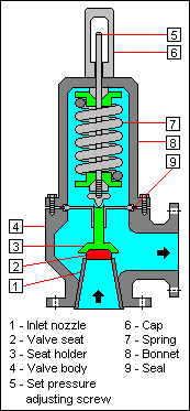
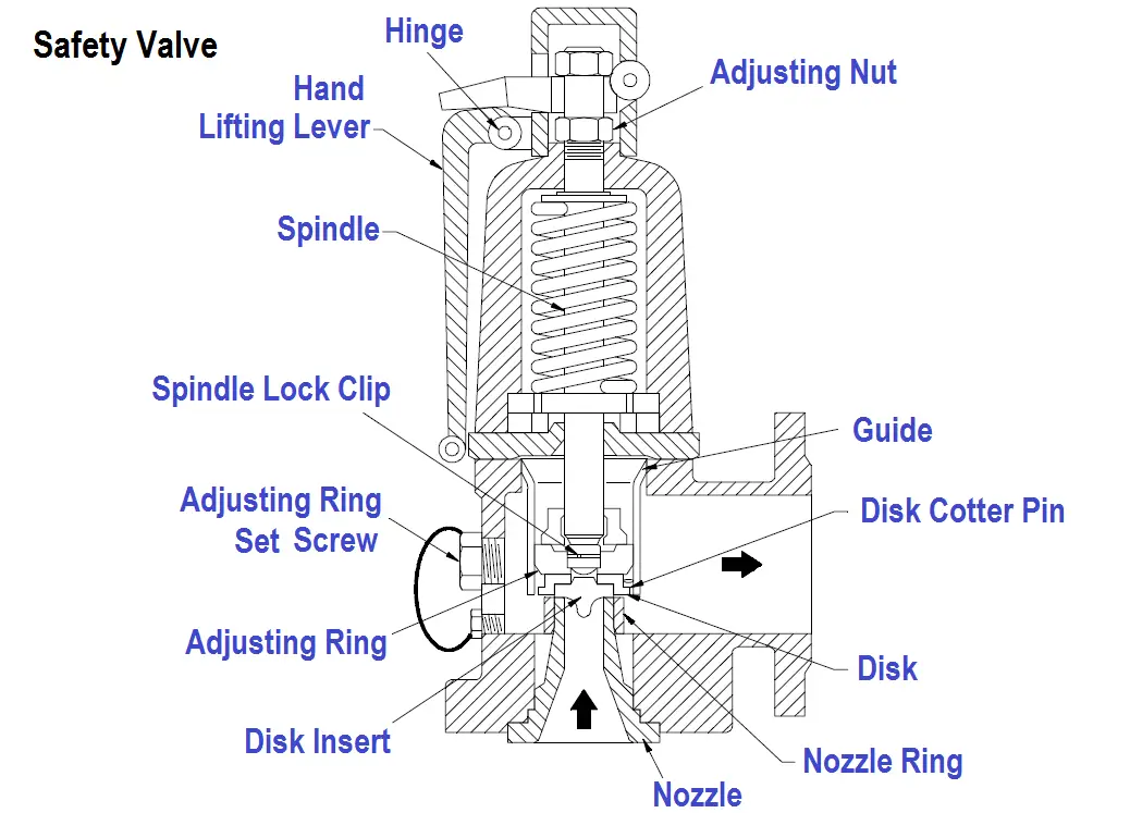
In a Spring loaded Pressure Safety Valve the closing force or spring force is applied by a helical spring which is compressed by an adjusting screw. The spring force is transferred via the spindle onto the disc. The disc seals against the nozzle as long as the spring force is larger than the force created by the pressure at the inlet of the valve. Figure 2 shows all the steps in working of Spring Loaded Pressure Safety Valves.
In an upset situation a safety valve will open at a predetermined set pressure. The spring force Fs is acting in closing direction and Fp, the force created by the pressure at the inlet of the safety valve, is acting in opening direction. At set pressure the forces Fs and Fp are balanced. There is no resulting force to keep the disc down on the seat. The safety valve will visibly or audibly start to leak (initial audible discharge).
As the pressure inside the system increases, the force Fp increase above the set pressure and the additional spring force required to further compress the spring is overcome. The valve will open rapidly with a “pop”, in most cases to its full lift.
In most applications a properly sized safety valve will decrease the pressure in the vessel when discharging. The pressure in the vessel will decrease at any subsequent point, but not later than the end of the upset situation. A decreasing pressure in the vessel will lower the force Fp. At set pressure however the flow is still acting on the enlarged disc area, which will keep the valve open. A further reduction in pressure is required until the spring force Fs is again greater than Fp and the safety valve begins to close. At the so called reseating pressure the disc will touch the nozzle again and the safety valve closes.
Pilot Operated Safety Valve is controlled by process medium. To achieve this, the system pressure is applied to the pilot valve (= control component for the main valve) via the pressure pickup. The pilot valve then uses the dome above the main valve piston to control the opening and closing of the main valve. Figure 4 shows all the steps in working of Pilot Operated Pressure Safety Valves.
During normal operation, the system pressure is picked up at the main valve inlet and routed to the dome. Since the dome area is larger than the area of the main valve seat, the closing force is greater than the opening force. This keeps the main valve tightly closed.
At set pressure, the pilot valve actuates. The medium is no longer routed to the dome. This prevents a further rise in dome pressure. Also, the dome is vented. As a result, the closing force ceases as a precondition for the system over-pressure to push the main valve open. Depending on the design of the pilot valve, this opening is either rapid and complete (Pop Action) or gradual and partial following system pressure (Modulate Action).
If system pressure drops to closing pressure, the pilot valve actuates and again routes the medium to the dome. The pressure in the dome builds up and the main valve closes either rapid and complete (Pop Action) or gradual and partial following system pressure (Modulate Action).
“Pressure Safety Valve” and “Pressure Relief Valve” are commonly used terms to identify pressure relief devices on a vessel or equipment. Although freely used interchangeably, these terms differ in the following aspect:
Pressure safety valve is the term used to describe relief device on a compressible fluid or gas filled vessel. For such a valve the opening is sudden. When the set pressure of the valve is reached, the valve opens almost fully.
Pressure relief valve is the term used to describe relief device on a liquid filled vessel. For such a valve the opening is proportional to increase in the vessel pressure. Hence the opening of valve is not sudden, but gradual if the pressure is increased gradually.
As soon as mankind was able to boil water to create steam, the necessity of the safety device became evident. As long as 2000 years ago, the Chinese were using cauldrons with hinged lids to allow (relatively) safer production of steam. At the beginning of the 14th century, chemists used conical plugs and later, compressed springs to act as safety devices on pressurised vessels.
Early in the 19th century, boiler explosions on ships and locomotives frequently resulted from faulty safety devices, which led to the development of the first safety relief valves.
In 1848, Charles Retchie invented the accumulation chamber, which increases the compression surface within the safety valve allowing it to open rapidly within a narrow overpressure margin.
Today, most steam users are compelled by local health and safety regulations to ensure that their plant and processes incorporate safety devices and precautions, which ensure that dangerous conditions are prevented.
The principle type of device used to prevent overpressure in plant is the safety or safety relief valve. The safety valve operates by releasing a volume of fluid from within the plant when a predetermined maximum pressure is reached, thereby reducing the excess pressure in a safe manner. As the safety valve may be the only remaining device to prevent catastrophic failure under overpressure conditions, it is important that any such device is capable of operating at all times and under all possible conditions.
Safety valves should be installed wherever the maximum allowable working pressure (MAWP) of a system or pressure-containing vessel is likely to be exceeded. In steam systems, safety valves are typically used for boiler overpressure protection and other applications such as downstream of pressure reducing controls. Although their primary role is for safety, safety valves are also used in process operations to prevent product damage due to excess pressure. Pressure excess can be generated in a number of different situations, including:
The terms ‘safety valve’ and ‘safety relief valve’ are generic terms to describe many varieties of pressure relief devices that are designed to prevent excessive internal fluid pressure build-up. A wide range of different valves is available for many different applications and performance criteria.
In most national standards, specific definitions are given for the terms associated with safety and safety relief valves. There are several notable differences between the terminology used in the USA and Europe. One of the most important differences is that a valve referred to as a ‘safety valve’ in Europe is referred to as a ‘safety relief valve’ or ‘pressure relief valve’ in the USA. In addition, the term ‘safety valve’ in the USA generally refers specifically to the full-lift type of safety valve used in Europe.
Pressure relief valve- A spring-loaded pressure relief valve which is designed to open to relieve excess pressure and to reclose and prevent the further flow of fluid after normal conditions have been restored. It is characterised by a rapid-opening ‘pop’ action or by opening in a manner generally proportional to the increase in pressure over the opening pressure. It may be used for either compressible or incompressible fluids, depending on design, adjustment, or application.
Safety valves are primarily used with compressible gases and in particular for steam and air services. However, they can also be used for process type applications where they may be needed to protect the plant or to prevent spoilage of the product being processed.
Relief valve - A pressure relief device actuated by inlet static pressure having a gradual lift generally proportional to the increase in pressure over opening pressure.
Relief valves are commonly used in liquid systems, especially for lower capacities and thermal expansion duty. They can also be used on pumped systems as pressure overspill devices.
Safety relief valve - A pressure relief valve characterised by rapid opening or pop action, or by opening in proportion to the increase in pressure over the opening pressure, depending on the application, and which may be used either for liquid or compressible fluid.
In general, the safety relief valve will perform as a safety valve when used in a compressible gas system, but it will open in proportion to the overpressure when used in liquid systems, as would a relief valve.
Safety valve- A valve which automatically, without the assistance of any energy other than that of the fluid concerned, discharges a quantity of the fluid so as to prevent a predetermined safe pressure being exceeded, and which is designed to re-close and prevent further flow of fluid after normal pressure conditions of service have been restored.

The extremist elements in India like Lala Lajpat Rai, Bal Gangadhar Tilak, Bipin Chandra Pal, etc. laid down the theory known as ‘Safety- valve’ theory.
Discovering the safety device used in most industry for pressure flow control, pressure relief valve it’s called. It’s an equipment that must be found in the industry to control an over-pressurized vessel.
So, a pressure relief valve is a safety device designed to secure a pressurized system during an overpressure occurrence during operation. The system is widely available today as an electronic, pneumatic and hydraulic system. The various types serve the same purpose in different applications and are called pressure relief valve, relief valve or safety valve.
Depending on the type of system, the power source could be electricity or compressed air for operation. Since its purpose is to control the pressure so that life and properties can be safe. A pressure relief valve must be capable to serve for a long period of time and capable of operating at all times. And a professional operator with experience must be in charge to ensure proper working as there is no room for error.
Today we’ll be looking at the definition, functions, applications, working, types, components, considerations, benefits and limitations of a pressure relief valve.
A pressure relief valve or relief valve is a special type of safety valve system used to control or limit the pressure in a system. It can be manually or automatically controlled from a pressurized vessel or piping system. The pressurized fluid or gas is discharged to a reservoir or atmosphere to relieve pressure in excess of the maximum allowable working pressure (MAWP).
The primary purpose of a pressure relief valve is to protect pressure vessels or system from catastrophic failure. Catastrophic failure could be disastrous during an overpressure event, could either be liquid or gaseous.
This device is widely used in petrochemical, petroleum refining, chemical manufacturing industries. Industries where natural gas processing occurs and power generation, as well as water supply industries, also make good use of pressure relief valve. Though it’s generally known as relief valve depending on its field of application it can be called pressure relief valve (PRV), pressure safety valve (PSV), or safety valve. You should note the design and operation of these valves are slightly different.
The working of a relief valve is quite complex but can be easily understood. It consists of ball, poppet or spool opposed by a spring which is placed into a cavity or ported body. A hydraulic system is often used to limit fluid pressure in the part of the circuit they are installed.
The poppet is in the form of a disc or cone shape object that is mounted within an opposite machine seat. If the part is forced closed by spring pressure, very low leakage will be providing. The spool is a cylindrical, machined steel rod with metering grooves or notches that’s also stopped by spring pressure. It leaks more than a poppet valve but offers superior metering effects.
In the working of a relief valve, excessive pressurized fluid is provided from an open path to a tank with the purpose of reducing work port pressure. As soon as the fluid pressure begins to rise, the force is applied to the bottom of the spool or poppet. This allows the valve to open modestly at first, bleeding little fluid as required to maintain the downstream pressure. But if the downstream pressure continues to rise, the force acting upon the poppet or spool will be pushing it further towards the spring until the point spring force is balanced by the hydraulic force.
The pressure rise is as a result of load pressure combination, backpressure, and energy required to flow through the valve itself. The initial fluid force overcomes the seated force of the spring by the help of the cracking pressure. As the valve flows more fluid to the tank, the rate of pressure rise is safe because the forces of the pressurized fluid counteract the compression rate of the spring. If the valve is nearly fully open, pressure rise increases again as the valve bottom opens due to the flow forces.
As the operation or backpressure decreases, the valve begins to close. This is done at differing rates than the opening. The difference between the opening and closing curve is called its hysteresis, it’s indicative and instruction of the quality of its construction. This is because higher quality valves with advanced construction allow lower pressure rise with better hysteresis.
the conventional spring-loaded types of relief valve that contained the bonnet, spring, and guide in the released fluids. Its relief pressure backpressure decreases the set pressure if the bonnet is vented to the atmosphere. But, if the bonnet is vented internally to the outlet, the relief-system backpressure increases the set pressure.
The pilot-operated valve is controlled by an auxiliary pressure pilot. The resistance force on the piston in the main valve is achieved by the pressure during the operation through an orifice. The net seating force on the piston actually rises as the process pressure nears the set point.
a safety valve is a pressure relief valve that works by inlet static pressure and design to rapidly open with a pop action. It is widely used for air and stream services. A safety valve is available in two forms:
Full-lift safety valve: in this safety valve the disc is also automatically lifted but the actual charge area is not determined by the position of the disc.
A relief valve is a pressure relief device design with an inlet static pressure for its working. It has a gradual lift generally proportional to the increase in pressure over opening pressure. It’s suitable for close discharge system as it is enclosed in a spring housing.
A safety relief valve is a pressure relief valve characterized by its rapid opening or pop action. Also known for its opening in proportion to the increase in pressure over the opening pressure base on its application. Safety relief valves are used either for liquid or compressible fluid. The common type is the conventional and balanced safety relief valve which were earlier explained.
A power actuated pressure relief valve contained a relieving device that is joined with and controlled by a device requiring an external source of energy.
A vacuum relief valve is a pressure relief device that admits fluid to prevent an excessive internal vacuum. It’s designed to reclose so as to prevent further flow of fluid after normal conditions have been restored.
Selecting appropriate relief devices to handle the imposed loads. Several components must be put into consideration. Parts like set pressure, backpressure, dual relief valve, multiple relief valves must suit the capacity of the relieving device.
In conclusion, a pressure relief valve is a safety device used in the industrial world to save lives and properties. We saw the various types and components of pressure relief valve, how it works and also selection consideration.


 8613371530291