
diaphragm safety valve free sample
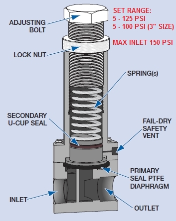
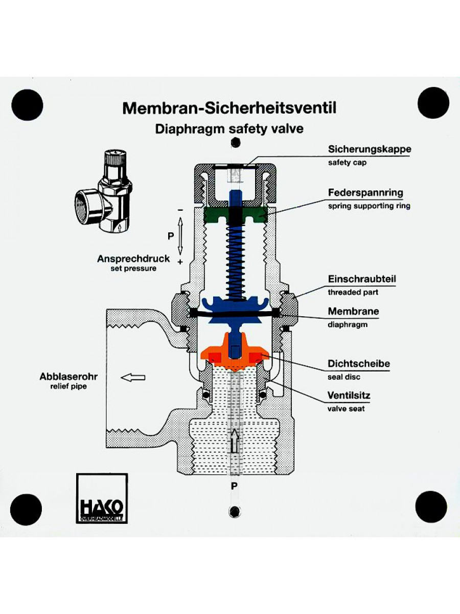
It uses a diaphragm structure with only highly inert wetted materials such as PTFE, PPS, and FFKM and can handle severe media with strong acids and strong alkalis.
The valve opens, and the media flows to the secondary port when the primary pressure exceeds the relief pressure, preventing the flow channel from rising further.

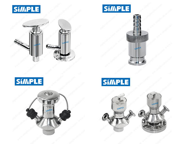
Manual, continuous, closed sampling systems for liquid and gaseous samples for a wide range of applications. These systems will take emission-free, representative samples while providing operator safety. Easy to install and to operate with the possibility of advanced versions. To meet the customer needs we can combine the panel with various options and accessories.

Back pressure valve / relief valve for fitting directly on the pump"s dosing head with the functions:Back pressure valve, opening pressure approx. 1.5 bar with free outlet or priming pressure at the suction end (black rotary dial)
The multifunctional valve is operated by free-moving rotary dials that automatically return to their original position when released by the operator. This means operation is possible even when access is difficult. The multifunctional valve is made of PVDF and can be used to meter almost any chemical.
Caution: Back pressure valves are not absolutely leak-tight shut-off devices! It is essential that you observe the installation notes in the operating instructions!
SealFKM and EPDM (loose)TypeRelief opening pressure *Connector sizeBypass connectorOrder no.*The relief opening pressure given above is the pressure at which the valve starts to open. The pressure may be up to 50% more than this before the valve is fully open depending on the type of pump.Size I16 bar6-126 x 4792011
Adjustable back pressure valve for fitting directly onto the dosing head to generate a constant back pressure. For accurate metering with a free outlet and with priming pressure on the suction side.
Please note: Back pressure valves are not absolutely leak-tight shut-off devices! It is essential that you observe the installation notes in the operating instructions!Applications:Metering pump alpha, beta, gamma/ X, gamma/XL, Pneumados b, EXTRONICTypeadjustable pressure max.Connector widthMaterialOrder no.
Adjustable back pressure valve for installation in the metering line to generate a constant back pressure for precise metering with a free outlet and with priming pressure on the suction side
When used as a back pressure valve in long lines to avoid resonance vibrations: Install at the end of the metering line or select a set pressure greater than the line pressure loss
Please note: Back pressure valves are not absolutely leak-tight shut-off devices! It is essential that you observe the installation notes in the operating instructions!Applications:Metering pumps alpha, beta , gamma/ X, gamma/XL, Pneumados b, EXTRONICTypeadjustable pressure max.Connector widthMaterialOrder no.
Pressure relief valves (safety relief valves) are designed to open at a preset pressure and discharge fluid until pressure drops to acceptable levels. The development of the safety relief valve has an interesting history.
Denis Papin is credited by many sources as the originator of the first pressure relief valve (circa 1679) to prevent overpressure of his steam powered “digester”. His pressure relief design consisted of a weight suspended on a lever arm. When the force of the steam pressure acting on the valve exceeded the force of the weight acting through the lever arm the valve opened. Designs requiring a higher relief pressure setting required a longer lever arm and/or larger weights. This simple system worked however more space was needed and it coud be easily tampered with leading to a possible overpressure and explosion. Another disadvantage was premature opening of the valve if the device was subjected to bouncing movement.
Direct-acting deadweight pressure relief valves: Later to avoid the disadvantages of the lever arrangement, direct-acting deadweight pressure relief valves were installed on early steam locomotives. In this design, weights were applied directly to the top of the valve mechanism. To keep the size of the weights in a reasonable range, the valve size was often undersized resulting in a smaller vent opening than required. Often an explosion would occur as the steam pressure rose faster than the vent could release excess pressure. Bouncing movements also prematurely released pressure.
Direct acting spring valves: Timothy Hackworth is believed to be the first to use direct acting spring valves (circa 1828) on his locomotive engine called the Royal George. Timothy utilized an accordion arrangement of leaf springs, which would later be replaced with coil springs, to apply force to the valve. The spring force could be fine tuned by adjusting the nuts retaining the leaf springs.
Refinements to the direct acting spring relief valve design continued in subsequent years in response to the widespread use of steam boilers to provide heat and to power locomotives, river boats, and pumps. Steam boilers are less common today but the safety relief valve continues to be a critical component, in systems with pressure vessels, to protect against damage or catastrophic failure.
Each application has its own unique requirements but before we get into the selection process, let’s have a look at the operating principles of a typical direct acting pressure relief valve.
In operation, the pressure relief valve remains normally closed until pressures upstream reaches the desired set pressure. The valve will crack open when the set pressure is reached, and continue to open further, allowing more flow as over pressure increases. When upstream pressure falls a few psi below the set pressure, the valve will close again.
Most commonly, pressure relief valves employ a spring loaded “poppet” valve as a valve element. The poppet includes an elastomeric seal or, in some high pressure designs a thermoplastic seal, which is configured to make a seal on a valve seat. In operation, the spring and upstream pressure apply opposing forces on the valve. When the force of the upstream pressure exerts a greater force than the spring force, then the poppet moves away from the valve seat which allows fluid to pass through the outlet port. As the upstream pressure drops below the set point the valve then closes.
Piston style designs are often used when higher relief pressures are required, when ruggedness is a concern or when the relief pressure does not have to be held to a tight tolerance. Piston designs tend to be more sluggish, compared to diaphragm designs due to friction from the piston seal. In low pressure applications, or when high accuracy is required, the diaphragm style is preferred. Diaphragm relief valves employ a thin disc shaped element which is used to sense pressure changes. They are usually made of an elastomer, however, thin convoluted metal is used in special applications. Diaphragms essentially eliminate the friction inherent with piston style designs. Additionally, for a particular relief valve size, it is often possible to provide a greater sensing area with a diaphragm design than would be feasible with a piston style design.
The reference force element is usually a mechanical spring. This spring exerts a force on the sensing element and acts to close the valve. Many pressure relief valves are designed with an adjustment which allows the user to adjust the relief pressure set-point by changing the force exerted by the reference spring.
The chemical properties of the fluid should be considered before determining the best materials for your application. Each fluid will have its own unique characteristics so care must be taken to select the appropriate body and seal materials that will come in contact with the fluid. The parts of the pressure relief valve in contact with the fluid are known as the “wetted” components. If the fluid is flammable or hazardous in nature the pressure relief valve must be capable of discharging it safely.
In many high technology applications space is limited and weight is a factor. Some manufactures specialize in miniature components and should be consulted. Material selection, particularly the relief valve body components, will impact weight. Also carefully consider the port (thread) sizes, adjustment styles, and mounting options as these will influence size and weight.
In many high technology applications space is limited and weight is a factor. Some manufactures specialize in miniature components and should be consulted. Material selection, particularly the relief valve body components, will impact weight. Also carefully consider the port (thread) sizes, adjustment styles, and mounting options as these will influence size and weight.
A wide range of materials are available to handle various fluids and operating environments. Common pressure relief valve component materials include brass, plastic, and aluminum. Various grades of stainless steel (such as 303, 304, and 316) are available too. Springs used inside the relief valve are typically made of music wire (carbon steel) or stainless steel.
The materials selected for the pressure relief valve not only need to be compatible with the fluid but also must be able to function properly at the expected operating temperature. The primary concern is whether or not the elastomer chosen will function properly throughout the expected temperature range. Additionally, the operating temperature may affect flow capacity and/or the spring rate in extreme applications.
Beswick Engineering manufactures four styles of pressure relief valves to best suit your application. The RVD and RVD8 are diaphragm based pressure relief valves which are suited to lower relief pressures. The RV2 and BPR valves are piston based designs.
GA industries Series 5000 are pilot-operated, diaphragm actuated water control valves.The GA Figure 5670 valve can be used in either of two applications:
Pressure Relief: installed on the side outlet of a tee and closed under normal pressure conditions.The valve opens upon a rise in pressure above normal to discharge water out of the system to safely limit the pressure increase
The valve is available with full port globe body up to 16" size or reduced port globe in 3" to 10" sizes, NPT connections to 3" and Class 150 or 300 flanged from 2" to 16".Full port angle body valves are available 1¼" to 10".
In many liquid piping systems, it is vital that line pressure is maintained within relatively narrow limits. This is the function of the 108 Pressure Relief / Back Pressure Series of the OCV control valves. Installed in the main flow line, the standard Model 108-2 acts as a backpressure or pressure sustaining valve. In this configuration, the valve maintains a constant upstream pressure regardless of fluctuating downstream demand. When used in a bypass line, the same model will function as a relief valve, protecting the system against potentially damaging surges.
Protects system from over pressure by exhausting excess pressure. The valve may only have to operate intermittently to prevent pressure surges that might occur on pump start, pump stop, or sudden downstream valve closure.
Valve allows flow when inlet pressure is above the set-point thus preventing inlet pressure from falling too low. Prevents demand from “robbing” the source, or keeps pump “on its curve.”
RELIEF VALVE – Closed under normal operating pressures. Valve opens when pressure rises to the set point. Valve will close when system pressure drops below set point.
2.) Model 1330 Pressure Relief Pilot, a two-way, normally-closed pilot valve which senses upstream pressure under its diaphragm and balances it against an adjustable spring load. An increase in upstream pressure tends to make the pilot open.
3.) Model 126 Ejector, a simple “tee” fitting with a fixed orifice in its inlet port. It provides the proper pressure to the diaphragm chamber of the main valve depending on the position of the pressure relief pilot.
4.) Model 141-3 Flow Control Valve, a needle-type valve which provides adjustable, restricted flow in one direction, and free flow in the opposite direction. On the 108-2, the flow control valve is connected as a closing speed control.
5.) Model 159 Y-Strainer (standard on water service valves) or Model 123 Inline Strainer (standard on fuel service valves). The strainer protects the pilot system from solid contaminants in the line fluid.
6A / 6B.) Two Model 141-4 Ball Valves (standard on water service valves, optional on fuel service valves), useful for isolating the pilot system for maintenance or troubleshooting.
The Model 1330/2400 Pressure Sustaining Pilot controls the amount of pressure in the upper chamber of the Main valve(s). (Hence, the degree of opening or closing of the Main valve). The upstream pressure increases, the pilot begins to open, decreasing the amount of pressure in the upper chamber of the main valve allowing it to open a proportionate amount, in order to maintain a constant inlet pressure. As the upstream pressure decreases, the pilot begins to close, allowing the pressure in the upper chamber of the main valve to increase causing it to close. This is a constant modulating action compensating for any change in upstream pressure.
For the most comprehensive procedure in sizing Series 108 control valves, it is best to use our ValveMaster software or the guidelines shown here in conjunction with the Performance Charts in the Engineering Section of the OCV catalog.
Bypass pressure control valves are sized based on maximum flow and pressure drop across the valve. The maximum flow through the valve is the pump flow at the desired set point (from the pump curve) minus the minimum system flow. The pressure drop across the valve is the set point minus the pressure at the valve discharge (typically pump suction or storage tank head). Determine the valve’s operating Cv using the maximum flow and pressure drop from the formula:
Size is determined by the amount of flow required to lower the inlet pressure. This relief flow can be difficult to determine, so a general guideline is to use 60% of the rated pump flow. The 108 Series valve is capable of intermittent flows up to 45 ft. per second. Relief valve sizes are typically 50-60% of the mainline size.
Many surge relief, and some bypass pressure control valves are, by their application, subject to pressure differentials that may induce cavitation. When these conditions exist, it may be only on an intermittent basis, causing minimum concern for valve deterioration.
By combining various control pilots, multiple valve functions can be performed on a single Series 108 Pressure Relief Valve. To find the combination function valve, select the desired features and then the model number. This chart shows only a sample of those most often specified valves. Consult the factory for specific data on the model you selected.
Combination valves can often reduce or eliminate other equipment. Example: If the system requires a Back Pressure Valve and a Check Valve, the check feature can be added as a function of the Back Pressure, Model 108-3.
When valve inlet pressure requires the model 2400 High Pressure Relief pilot, an HP is added to the end of the model number. Example: Standard model 108-2 (inlet ranges from 5 – 300 psi) Model 108-2HP (outlet ranges 200-750 psi)
For maximum efficiency, the OCV control valve should be mounted in a piping system so that the valve bonnet (cover) is in the top position. Other positions are acceptable but may not allow the valve to function to its fullest and safest potential. In particular, please consult the factory before installing 8″ and larger valves, or any valves with a limit switch, in positions other than described. Space should be taken into consideration when mounting valves and their pilot systems.
Series Number – Valve size – Globe or Angle – Pressure Class – Screwed, Flanged, Grooved – Trim Material – Adjustment Range – Pilot Options – Special needs / or installation requirements.


 8613371530291