
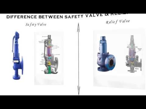
difference between pressure relief valve and safety valve free sample

As you already know, there are a multitude of pressure relief valves out there. In the industry, we tend to use terms like safety valve and relief valve interchangeably. And for the most part, this makes sense. Most pressure relief valves are designed to do the same thing — release pressure in a system.
But is there a difference between some of these commonly used terms, and if so, what does it mean for you? Here’s a quick breakdown of two popular terms: safety valve vs. relief valve.
While both terms refer to valves used to release pressure from a pressurized system, their technical definitions are a bit different. In general, the term relief valve refers to a valve within a pressurized system that is used to control pressure for the optimal functionality of the system. Relief valves are designed to help your facility avoid system failures, and protect equipment from overpressurized conditions.
The term safety valve, on the other hand, refers to pressure valves that are designed to protect people, property, and processes. In other words, the term safety valve refers to a failsafe, last resort valve that will release pressure to prevent a catastrophe, usually in the event that all other relief valves have failed to adequately control pressure within a system.
The general purpose of both safety valves and relief valves are the same. Both are pressure relief valves, and they are designed to let off pressure in any situation where a system becomes overpressurized. That said, relief valves and safety valves do function slightly differently:
Relief Valves are designed to control pressure in a system, most often in fluid or compressed air systems. These valves open in proportion to the increase in system pressure. This means they don’t fly all the way open when the system is slightly overpressure. Instead, they open gradually, allowing the system to return to the preset pressure level. When that level is reached, the valve shuts again.
Safety Valves are used for one reason — safety. Instead of controlling the pressure in a system, they’re designed to immediately release pressure in the event of an emergency or system failure. Unlike relief valves, safety valves open immediately and completely to avoid a disaster, rather than to control the pressure of a system.
While both safety valves and relief valves work to release excess pressure, the way they go about it is a little different. Check out this table, courtesy of Difference Between, for a little more information about the differences between the two valves:

Industrial equipment often uses either safety or relief valves to prevent damaging pressure levels from building up. Though they perform similar functions, there are some critical differences between safety and relief valves. Understanding these two valves’ differences is essential for proper pressure system operation. So here we discuss the pressure safety valve vs pressure relief valve.
A pressure relief valve is a device that releases pressure from a system. The relief valve is generally immune to the effects of back pressure and must be periodically stripped down. Pressure relief valves are one the essential parts of a pressure system to prevent system failures. They are set to open at a predetermined pressure level. Each pressure system has a setpoint that is a predetermined limit. The setpoint determines when the valve will open and prevents overpressure.
Pressure relief valves are typically used in gas or liquid systems where there is a need to prevent excessive pressure from building up. When the pressure in the system reaches a certain level, the valve will open and release the pressure. Pressure relief valves are an essential safety feature in many designs and can help to prevent damage to the system or components.
PRVs are generally considered to be safe and reliable devices. However, before installing a PRV in a system, some potential disadvantages should be considered. Here are five pros and cons of pressure relief valves:
Pros: Pressure relief valves are anessential safety feature in many systems. They protect against over-pressurization by relieving excess pressure from the system. This can help to prevent severe damage or even explosions.
Pressure relief valves can help to improve the efficiency of a system. The system can operate at lower overall pressure by relieving excess pressure and saving energy.
Pressure relief valves can be used as a safety device in systems that are susceptible to overpressurization. By relieving pressure before it builds up to a dangerous level, they can help to prevent accidents and injuries.
Cons: Pressure relief valves can be a potential source of leaks. If not properly maintained, the valve may not seat properly and can allow fluids or gasses to escape.
Pressure relief valves can sometimes cause problems if they do not open or close properly. This can lead to process disruptions and may cause safety issues.
A pressure safety valve is a device used to release pressure from a system that has exceeded its design limit. This safety valve is a fail-safe device. This type of valve is typically used in systems that contain fluids or gasses under high pressure. Pressure safety valves are designed to open and release pressure when the system has exceeded its maximum pressure limit. This helps to prevent the system from rupturing or exploding.
Pressure safety valves are an essential part of many different types of systems and can help keep both people and property safe. If anyone is ever in a situation where they need to release pressure from a system, it is essential to know how to use a pressure safety valve correctly.
A pressure safety valve (PSV) is a type used to relieve a system’s pressure. PSVs are commonly used in chemical and process industries, as well as in some kinds of pressure vessels. There are both advantages and disadvantages to using a PSV. Some of the pros of using a PSV include: PSVs can help to prevent overpressurization, which can be dangerous.
A safety valve is a pressure relief device used to prevent the over-pressurization of a system. On the other hand, a relief valve is a device used to relieve pressure from a system that is already overpressurized. Function Of Pressure Relief Valve Vs Safety Valve
The function of a pressure relief valve is to protect a system or component from excess pressure. A safety valve, on the other hand, is designed to protect from overpressurization. Both types of valves are used in various industries, but each has unique benefits and drawbacks.
Pressure relief valves are typically used in systems where a small amount of overpressure can cause damage. On the other hand, safety valves are designed for systems where overpressurization could be catastrophic. Both valves have advantages and disadvantages, so choosing the right type of valve for the specific application is essential.
Relief valves are usually set to open at a specific pressure and will close once the pressure has been relieved. Safety valves are similar in that they are also used to protect equipment from excessive pressure. However, safety valves are designed to stay open until they are manually closed. This is because safety valves are typically used in applications where it is not safe to have a closed valve, such as in a gas line. Operation Of Safety Relief Valve Vs Pressure Relief Valve
Two types of valves are commonly used in industrial settings: relief valves and safety valves. Both of these valves serve essential functions, but they operate in different ways.
Relief valves are designed to relieve pressure build-up in a system. They open when the system pressure reaches a certain point, which allows excess pressure to be released. On the other hand, safety valves are designed to prevent accidents by preventing system pressure from getting too high. They open when the system pressure reaches a certain point, which allows excess pressure to be released before an accident can occur.
So, which valve is better? That depends on the situation. A relief valve is the better option to protect the system from pressure build-up. If anyone need to protect the system from accidents, then a safety valve is the better option Setpoint Of Pressure Relief Valve Vs Safety Relief Valve
The relief valve is made to open when it reaches a specific pressure, commonly described as a “setpoint”. Setpoints shouldn’t be misinterpreted as the pressure set. A setpoint on a relief valve is set to the lowest possible pressure rating, which means it is set to the lowest system pressure before an overpressure situation is observed. The valve will open as the pressure increases to a point higher than the setpoint. The setting point is determined as pounds per square inch (PSIG) and should be within the maximum allowed operating pressure (MAWP) limits. In safety valves, the setpoint is typically placed at about 3 percent over the working pressure level, whereas relief valves are determined at 10 percent.
No, the safety valve and relief valve can not be used interchangeably. Though both valves are seal butterfly valve and used for safety purposes, they serve different functions. A safety valve relieves excess pressure that builds up in a system, while a relief valve regulates the pressure in a system.
Knowing the difference between these two types of valves is essential, as using the wrong valve for the intended purpose can potentially be dangerous. If unsure which type of valve to use, it is always best to consult with a professional.
A few key points help us understand the safety valve vs pressure relief valve. Safety valves are designed to relieve pressure in a system when it gets too high, while relief valves are designed to relieve pressure when it gets too low. Safety valves are usually set to open at a specific pressure, while relief valves are generally open at a particular vacuum. Safety valves are typically intended for one-time use, while relief valves can be used multiple times. Choose the trusted valve manufactureraccording to the specific business needs.

In the process industry, both terms refer to safety devices, which generally come in the form of valves, cylinders, and other cylinders that protect people, property, and the environment. Safety valves and relief valves are integral components of process safety. However, they are used for almost identical purposes. Their main difference lies in their operating mechanisms.
In the event of an overpressure, a safety valve or pressure relief valve (PRV) protects pressure-sensitive equipment. It is recommended to strip down relief valves regularly and prevent serious damage due to backpressure. Pressure relief valves are a crucial part of any pressurized system. In order to prevent system failures, you can set the pressure to open at predetermined levels. A setpoint, also known as a predetermined design limit, is set for all pressure systems. When the setpoint is exceeded, an overpressure valve opens.
A relief valve, illustrated in Below Figure, gradually opens as the inlet pressure increases above the setpoint. A relief valve opens only as necessary to relieve the over-pressure condition.
A safety valve, illustrated in Below Figure, rapidly pops fully open as soon as the pressure setting is reached. A safety valve will stay fully open until the pressure drops below a reset pressure.
The reset pressure is lower than the actuating pressure setpoint. The difference between the actuating pressure setpoint and the pressure at which the safety valve resets is called blowdown.
Relief valves are typically used for incompressible fluids such as water or oil. Safety valves are typically used for compressible fluids such as steam or other gases.
There are various types of safety valves used in several types of industries, including power plants, petrochemical plants, boilers, oil and gas, pharmaceuticals, and more. Using safety valves helps to prevent accidents and injuries that can harm people, property, and processes. Pressure builds up in vessels and systems automatically when the device is activated above a preset level. Safety valves must be configured so that their prescribed pressure is exceeded in order for them to function (i.e., relieve pressure). Ideally, excess pressure should be released either to the atmosphere or back into the pneumatic system to prevent damage to the vessel. In addition, excess pressure should be released to keep pressure within a certain range. As soon as a slight increase in pressure above the desired limit has lifted the safety valve, it opens.
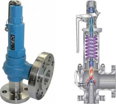
As indicated in Below Figure, system pressure provides a force that is attempting to push the disk of the safety valve off its seat. Spring pressure on the stem is forcing the disk onto the seat.
At the pressure determined by spring compression, system pressure overcomes spring pressure and the relief valve opens. As system pressure is relieved, the valve closes when spring pressure again overcomes system pressure.
Most relief and safety valves open against the force of a compression spring. The pressure setpoint is adjusted by turning the adjusting nuts on top of the yoke to increase or decrease the spring compression.
Valve relief removes excessive pressure from a system by limiting its pressure level to a safe level. Often referred to as pressure relief valves (PRVs) or safety relief valves, these valves provide relief from pressure. The purpose of a relief valve is, for example, to adjust the pressure within a vessel or a system so that a specific level is maintained. The goal of a relief valve, unlike a safety valve, is not to prevent damage to the vessel; rather, it is to control the pressure limit of a system dynamically depending on the requirements. Conversely, safety valves have a maximum allowable pressure set at a certain level, which allows escaping liquid or gas whenever the pressure exceeds it, eliminating damage to the system. It is imperative that safety valves are installed in a control system to prevent the development of pressure fluctuations that can cause property damage, life loss, and environmental pollution.
The hydraulic system relies on a pressure relief system in order to regulate the running pressure. By allowing excess pressure to escape from the pressurized zone, pressure relief valves and safety valves prevent overpressure when the pressure in the system reaches a predefined limit. By venting excess pressure through a relief port, or returning it through a return line, a pneumatic system can enable the excess pressure to escape into the atmosphere. Pump-driven pressure generators and control media that cannot be vented into the atmosphere are typical examples of this type of application.
Excess pressure may be relieved from the system using relief valves and safety valves. The valve opening increases proportionally as the vessel pressure increases with the relief valve. Gradually opening the valve rather than abruptly releasing only a prescribed amount of fluid. As pressure is reduced, the release proceeds at this rate until the pressure drops. By contrast, an emergency safety valve operates automatically when a predetermined pressure is reached in the system, preventing a catastrophic system failure. When the system is under excessive stress, the safety valve regulates the pressure within the system and prevents overpressure.
Defining a “setpoint” is the process of defining a pressure level that triggers the device to vent excess pressure. Setpoint is different from pressure. Overpressure is prevented by setting these devices lower than the highest pressure the system can handle before overpressure occurs. Setting the device below this pressure prevents overpressure. The valve opens when pressure rises above the setpoint. A setpoint also known as the maximum allowable working pressure (MAWP) cannot be exceeded when deciding the pressure in pounds per square inch (PSIG). The adjustment points for safety valves are generally 3 percent above working pressures, while adjustment points for relief valves are 10% above working pressures.
Pressure in an auxiliary passage can be controlled by a safety valve as well as a relief valve by releasing excess pressure. Safety valves of this type are pressure-sensitive and reliable. Safety valves can be categorized according to their capacity and setpoint, although both terms often refer to safety valves. Self-opening devices open automatically when maximum allowable pressure has been reached rather than being manually activated to prevent over-pressurizing. Contrary to relief valves, safety valves are typically used for venting steam or vapor into the atmosphere. Relief valves regulate fluid flow and compressed air pressure and gases, whereas safety valves typically regulate steam and vapor venting. Put simply, relief valves are used for more gradual pressure control requiring accurate, dynamic systems, whereas safety valves are used for one set to prevent damage to a system.
Pilot-operated relief valves are designed to maintain pressure through the use of a small passage to the top of a piston that is connected to the stem such that system pressure closes the main relief valve.

Safety valves and relief valves have similar structure and performance, both of which discharge internal media automatically when the pressure exceeds the set value to ensure the safety of the production device. Because of this essential similarity, the two are often confused and their differences are often overlooked as they are interchangeable in some production facilities. For a clearer definition, please refer to the ASME boiler and pressure vessel specifications.
Safety Valve: An automatic pressure control device driven by the static pressure of the medium in front of the valve is used for gas or steam applications, with full open action.
The basic difference in their operating principle: The safety valve relieves the pressure into the atmosphere i.e. out of the system, it can be a pressure relief device of fluid vessels, when the set pressure value reached then the valve opens almost fully. On the contrary, relief valve relieves the pressure by relieving the fluid back into the system, that’s the low-pressure side. Relief valve opens gradually if the pressure increased gradually.
The difference is also generally shown in capacity and setpoint. A relief valve is used to relieve pressure to prevent an overpressure condition, the operator may be needed to assist in opening the valve in response to a control signal and close back once it relieves the excess pressures and continues to operate normally.
A safety valve can be used to relieve the pressure that does not need a manual reset. For example, a thermal relief valve is used to bleed off pressure in a heat exchanger if it is isolated but the possibility of thermal expansion of the fluid could cause overpressure conditions. The safety valve on a boiler or other types of fired pressure vessels must be capable of removing more energy that is possible to be put into the vessel.
In short, Safety valves and relief valves are the two most commonly used types of control valves. The safety valve belongs to the pressure release device, which can only operate when the working pressure exceeds the allowable range to protect the system. The relief valve can make the high-pressure medium quickly to meet the pressure requirements of the system and its working process is continuous.

Both the terms are used interchangeably in the process industry as every pressurized system requires safety devices to protect life, property, and environment. Relief valves and safety valves are the two principle safety devices designed to prevent overpressure conditions in process industries. Although, both the devices are used almost for the same purpose, the difference lies mainly in how they operate.
Relief valves, or commonly known as pressure relief valves (PRVs), belong to the family of protective devices specifically designed to protect pressure-sensitive systems and equipment from the damaging effects of overpressure conditions. A relief valve device is basically immune to the back pressure effects of a system and is subject to periodic stripdown. Pressure relief valves are one of the most critical parts of a pressure system that are set to open at a preset pressure level in order to avoid system failures. Every pressure system is set with a predetermined design limit called a setpoint, above which the valve begins to open to prevent overpressure conditions.
A safety valve is the last resort of people, property, and processes in the process industry comprising of power plants, petrochemicals, boilers, oil and gas, pharmaceuticals, and many more. It’s kind of a fail-safe device that actuates automatically in order to prevent the accumulation of pressure in a vessel or system beyond a preset limit. The device is so designed so that the safety valve trips automatically when the given pressure is attained. It simply allows the excess pressure to escape in order to prevent any damage to the vessel. Additionally, it also makes sure the pressure remains within the limits in the future. Even a slight increment in pressure lifts the safety valve and it closes as soon as the pressure is reduced to the prescribed limit.
A relief valve, also known as pressure relief valve (PRV) or safety relief valve, is type of a safety valve device used to limit or control the pressure level in a system within a safe threshold limit to avoid an overpressure condition. In simple terms, a relief valve is a device designed to control the pressure in a vessel or system to a specific set level. A safety valve, on the other hand, is a device used to let go excess pressure from a vessel or equipment when the pressure crosses a certain predetermined limit. It simply allows liquids or gases to escape if the pressure gets too high to prevent any damage.
Pressure relief valves are mainly used in hydraulic systems to limit the pressure in the system to a specific preset level and when the pressure reaches the safety design limit, the relief valve responds by releasing the excess flow from an auxiliary passage from the system back to the tank in order to prevent equipment failure. The main purpose of a safety valve is to protect life, property, and environment against failure in the control system pressure. Simply put, a safety valve opens when the pressure exceeds the designed set pressure limit.
For a safety relief valve, the opening is directly proportional to the increase in the vessel pressure. This means the opening of the valve is rather gradual than sudden, allowing it to open only at a preset pressure level and release fluids until the pressure drops to the desired set pressure. A safety valve, on the other hand, will open immediately when the system pressure reaches the set pressure level in order to system failure. It is safety device capable of operating at all times and is the last resort to prevent catastrophic failure in systems under overpressure conditions.
A pressure relief valve is designed to open at a certain pressure level which is generally called as a “setpoint”. A setpoint should not be confused with the set pressure. In fact, a setpoint of a relief valves is adjusted to the lowest maximum pressure rating meaning it is set below the maximum system pressure allowed before the overpressure condition occurs. The valve begins to open when the pressure reaches up to some level above the setpoint. The setpoint is measured in pounds per square inch (PSIG) and must not exceed the maximum allowable working pressure (MAWP). In safety valves, the setpoint is usually set at 3 percent above the working pressure level whereas in relief valves, it is set at 10 percent.
Both relief valves and safety valves are high-performance pressure-sensitive safety devices so designed to control or limit the pressure inside the system or vessel by releasing the excessive pressure from the auxiliary passage out of the system. Although both are common terms used for safety valves, the difference lies mainly in the capacity and setpoint. While the former is operator-assisted and is designed to relieve pressure in order to avoid overpressure condition, the latter is a self-operated device which opens automatically when the maximum allowable pressure is reached. Relief valves are mostly used in fluid or compressed air systems, whereas safety valves are mainly used to release vapor or steam into the atmosphere.
Sagar Khillar is a prolific content/article/blog writer working as a Senior Content Developer/Writer in a reputed client services firm based in India. He has that urge to research on versatile topics and develop high-quality content to make it the best read. Thanks to his passion for writing, he has over 7 years of professional experience in writing and editing services across a wide variety of print and electronic platforms.
Outside his professional life, Sagar loves to connect with people from different cultures and origin. You can say he is curious by nature. He believes everyone is a learning experience and it brings a certain excitement, kind of a curiosity to keep going. It may feel silly at first, but it loosens you up after a while and makes it easier for you to start conversations with total strangers – that’s what he said."
The difference is generally in capacity and setpoint. A relief valve is ment to relieve pressure to prevent an over pressure condition. A relief valve may have an operator on it to assist in opening the valve in response to a control signal. A safety valve is ment to relieve pressure without operator assistance and a safety valve, or combination of safety valves, must be have a capacity to relieve more than the energy input to the volume being protected.
For example, a thermal relief valveis used to bleed off pressure in a heat exchanger if the heat exchanger is isolated but the possibility of thermal expansion of the fluid could cause over pressure conditions. The capacity of thermal reliefs are generally small.
A safey valve on a boiler or other types of fired pressure vessels must be capable of removing more energy that is possible to be put into the vessel. 110 percent of boiler rated capacity may be acceptable. The ASME Boiler & Pressure Vessel Code would be the source to check for adaquatley sizing safety valves.

Pressure relief valves are a type of safety valve that are commonly used to protect a system and the people operating it. Whereas pressure regulators take incoming line pressure and regulates it down to the pressure that is required by the downstream system. Pressure Regulators can be used for reasons of safety and/or cost. Both of these valves are very important to its specific application. In this article, we will discuss the difference between a pressure relief valve and regulator.
Pressure Regulators take an incoming line pressure and regulate it down to the pressure that is required by the downstream system. This may be for other instrumentation to operate effectively or simply to control the output flow of a pipe. Lower system pressures mean less risk and lower running costs and a reduced risk of air loss through a system. Pressure regulators can be used in many applications including pneumatics, compressed air and water.
There are various kinds of pressure regulators available within MGA Controls range – from general purpose units covering everyday industrial applications to more specialised precision pressure regulators, manifold regulators, pilot operated regulators and large capacity pilot operated versions. View our full range of pressure regulators in our store.
Pressure relief valves are used to control or limit pressure spikes in a compressed air system. When the system pressure increases beyond a predetermined set point, the valve opens and relieves that pressure, bringing it back in line with normal operating parameters. The main function of a Pressure relief valve is to vent excess pressure and protect other system components, all the while maintaining optimum performance.
Air systems benefit highly from pressure relief valves, however different types of pressure relief valves can be used in a wide range of industries. For example, the water industry utilises the valve to make sure water pressure doesn’t reach such a level that it will burst pipes.
The IMI Norgren Olympian Plus pressure relief valve is designed to protect compressed air systems against over-pressurisation. It has high relief capacity while being sensitive and accurate. As part of the Olympian Plus range of products, it is suitable for in-line or modular installation and is compatible with other products in the Olympian Plus range, such as the B64G Filter/Regulator and the L64 Series Lubricator. Some of the key pressure relief valve features include:
Choosing a pressure relief valve isn’t always easy, but here at MGA Controls, we specialise in helping you choose the correct valve for your application. There are six basic factors to consider before choosing your pressure relief valve:
You must also consider the physical dimensions of the application and the plant, as well as factors related to the environment in which the valve will operate.
Here at MGA Controls, pressure relief valves can be fitted to an existing system and can be specified in sizes ranging from 1/4″ to 1.1/2″. We carry a wide range of stock that is available for quick delivery in your time of need.
To speak to a member of our technical team about choosing a pressure relief valve or the difference between a pressure relief valve and regulator contact us today on 01704 898980 or email sales@mgacontrols.co.uk. To request a free quote or view our general range of products contact our team.
Safety valves and pressure relief valves are crucial for one main reason: safety. This means safety for the plant and equipment as well as safety for plant personnel and the surrounding environment.
Safety valves and pressure relief valves protect vessels, piping systems, and equipment from overpressure, which, if unchecked, can not only damage a system but potentially cause an explosion. Because these valves play such an important role, it’s absolutely essential that the right valve is used every time.
The valve size must correspond to the size of the inlet and discharge piping. The National Board specifies that the both the inlet piping and the discharge piping connected to the valve must be at least as large as the inlet/discharge opening on the valve itself.
The connection types are also important. For example, is the connection male or female? Flanged? All of these factors help determine which valve to use.
The set pressure of the valve must not exceed the maximum allowable working pressure (MAWP) of the boiler or other vessel. What this means is that the valve must open at or below the MAWP of the equipment. In turn, the MAWP of the equipment should be at least 10% greater than the highest expected operating pressure under normal circumstances.
Temperature affects the volume and viscosity of the gas or liquid flowing through the system. Temperature also helps determine the ideal material of construction for the valve. For example, steel valves can handle higher operating temperatures than valves made of either bronze or iron. Both the operating and the relieving temperature must be taken into account.
Back pressure, which may be constant or variable, is pressure on the outlet side of the pressure relief valve as a result of the pressure in the discharge system. It can affect the set pressure of the upstream valve and cause it to pop open repeatedly, which can damage the valve.
For installations with variable back pressure, valves should be selected so that the back pressure doesn’t exceed 10% of the valve set pressure. For installations with high levels of constant back pressure, a bellows-sealed valve or pilot-operated valve may be required.
Different types of service (steam, air, gas, etc.) require different valves. In addition, the valve material of construction needs to be appropriate for the service. For example, valves made of stainless steel are preferable for corrosive media.
Safety valves and relief valves must be able to relieve pressure at a certain capacity. The required capacity is determined by several factors including the geometry of the valve, the temperature of the media, and the relief discharge area.
These are just the basic factors that must be considered when selecting and sizing safety valves and relief valves. You must also consider the physical dimensions of the equipment and the plant, as well as other factors related to the environment in which the valve will operate.
In order to ensure that the maximum allowable accumulation pressure of any system or apparatus protected by a safety valve is never exceeded, careful consideration of the safety valve’s position in the system has to be made. As there is such a wide range of applications, there is no absolute rule as to where the valve should be positioned and therefore, every application needs to be treated separately.
A common steam application for a safety valve is to protect process equipment supplied from a pressure reducing station. Two possible arrangements are shown in Figure 9.3.3.
The safety valve can be fitted within the pressure reducing station itself, that is, before the downstream stop valve, as in Figure 9.3.3 (a), or further downstream, nearer the apparatus as in Figure 9.3.3 (b). Fitting the safety valve before the downstream stop valve has the following advantages:
• The safety valve can be tested in-line by shutting down the downstream stop valve without the chance of downstream apparatus being over pressurised, should the safety valve fail under test.
• When setting the PRV under no-load conditions, the operation of the safety valve can be observed, as this condition is most likely to cause ‘simmer’. If this should occur, the PRV pressure can be adjusted to below the safety valve reseat pressure.
Indeed, a separate safety valve may have to be fitted on the inlet to each downstream piece of apparatus, when the PRV supplies several such pieces of apparatus.
• If supplying one piece of apparatus, which has a MAWP pressure less than the PRV supply pressure, the apparatus must be fitted with a safety valve, preferably close-coupled to its steam inlet connection.
• If a PRV is supplying more than one apparatus and the MAWP of any item is less than the PRV supply pressure, either the PRV station must be fitted with a safety valve set at the lowest possible MAWP of the connected apparatus, or each item of affected apparatus must be fitted with a safety valve.
• The safety valve must be located so that the pressure cannot accumulate in the apparatus viaanother route, for example, from a separate steam line or a bypass line.
It could be argued that every installation deserves special consideration when it comes to safety, but the following applications and situations are a little unusual and worth considering:
• Fire - Any pressure vessel should be protected from overpressure in the event of fire. Although a safety valve mounted for operational protection may also offer protection under fire conditions,such cases require special consideration, which is beyond the scope of this text.
• Exothermic applications - These must be fitted with a safety valve close-coupled to the apparatus steam inlet or the body direct. No alternative applies.
• Safety valves used as warning devices - Sometimes, safety valves are fitted to systems as warning devices. They are not required to relieve fault loads but to warn of pressures increasing above normal working pressures for operational reasons only. In these instances, safety valves are set at the warning pressure and only need to be of minimum size. If there is any danger of systems fitted with such a safety valve exceeding their maximum allowable working pressure, they must be protected by additional safety valves in the usual way.
In order to illustrate the importance of the positioning of a safety valve, consider an automatic pump trap (see Block 14) used to remove condensate from a heating vessel. The automatic pump trap (APT), incorporates a mechanical type pump, which uses the motive force of steam to pump the condensate through the return system. The position of the safety valve will depend on the MAWP of the APT and its required motive inlet pressure.
This arrangement is suitable if the pump-trap motive pressure is less than 1.6 bar g (safety valve set pressure of 2 bar g less 0.3 bar blowdown and a 0.1 bar shut-off margin). Since the MAWP of both the APT and the vessel are greater than the safety valve set pressure, a single safety valve would provide suitable protection for the system.
However, if the pump-trap motive pressure had to be greater than 1.6 bar g, the APT supply would have to be taken from the high pressure side of the PRV, and reduced to a more appropriate pressure, but still less than the 4.5 bar g MAWP of the APT. The arrangement shown in Figure 9.3.5 would be suitable in this situation.
Here, two separate PRV stations are used each with its own safety valve. If the APT internals failed and steam at 4 bar g passed through the APT and into the vessel, safety valve ‘A’ would relieve this pressure and protect the vessel. Safety valve ‘B’ would not lift as the pressure in the APT is still acceptable and below its set pressure.
It should be noted that safety valve ‘A’ is positioned on the downstream side of the temperature control valve; this is done for both safety and operational reasons:
Operation - There is less chance of safety valve ‘A’ simmering during operation in this position,as the pressure is typically lower after the control valve than before it.
Also, note that if the MAWP of the pump-trap were greater than the pressure upstream of PRV ‘A’, it would be permissible to omit safety valve ‘B’ from the system, but safety valve ‘A’ must be sized to take into account the total fault flow through PRV ‘B’ as well as through PRV ‘A’.
A pharmaceutical factory has twelve jacketed pans on the same production floor, all rated with the same MAWP. Where would the safety valve be positioned?
One solution would be to install a safety valve on the inlet to each pan (Figure 9.3.6). In this instance, each safety valve would have to be sized to pass the entire load, in case the PRV failed open whilst the other eleven pans were shut down.
If additional apparatus with a lower MAWP than the pans (for example, a shell and tube heat exchanger) were to be included in the system, it would be necessary to fit an additional safety valve. This safety valve would be set to an appropriate lower set pressure and sized to pass the fault flow through the temperature control valve (see Figure 9.3.8).

For pressures over 3,200 psig (22.1 MPa), the value of W shall be multiplied by the appropriate supercritical correction factor, Ksc, from Table PG-69.2.3.
PG-69.3 If a manufacturer wishes to apply the Code symbol to a power-actuated pressure relieving valve under PG-67.4.1, one valve of each combination of inlet pipe size and orifice size to be used with that inlet pipe size shall be tested. The valve shall be capacity tested at four different pressures approximately covering the range of the certified test facility on which the tests are conducted. The capacities, as determined by these four tests, shall be plotted against the absolute flow test pressure and a line drawn through these four test points. All points must lie within ±5% in capacity value of the plotted line and must pass through 0-0. From the plotted line, the slope of the line dW/dP shall be determined and a factor of (0.90/51.45) x (dW/dP) shall be applied to capacity computations in the supercritical region at elevated pressures by means of the isentropic flow equation.
NOTES: The constant 1,135.8 is based on a g factor of 1.30, which is accurate for superheated steam at temperature above approximately 800°F (430°C). In interest of accuracy, other methods of capacity computations must be used at temperatures below 800°F (430°C) at supercritical pressures.
PG-69.4 Power-actuated pressure relieving valves, having capacities certified in accordance with the provision of PG-69.3 and computed in accordance with the formula contained therein, shall be marked as required by PG-110 with the computed capacity, corresponding to 3% above the full load operating pressure and temperature conditions at the valve inlet when the valve is operated by the controller, and they shall also be stamped with the set pressure of the controller. When the valve is marked as required by this paragraph, it shall be the guarantee by the manufacturer that the valve also conforms to the details of construction herein specified.
PG-69.6 When changes are made in the design of a safety or safety relief valve in such a manner as to affect the flow path, lift, or performance characteristics of the valve, new tests in accordance with this Section shall be performed.
PG-70.1 Subject to the minimum number required by PG-67.1, the number of pressure relief valves required shall be determined on the basis of the maximum designed steaming capacity, as determined by the boiler Manufacturer, and the relieving capacity marked on the valves by the manufacturer.
PG-71.1 When two or more pressure relief valves are used on a boiler, they may be mounted either separately or as twin valves made by placing individual valves on Y-bases, or duplex valves having two valves in the same body casing. Twin valves made by placing individual valves on Y-bases, or duplex valves having two valves in the same body, shall be of approximately equal capacity.
When not more than two valves of different sizes are mounted singly the relieving capacity of the smaller valve shall be not less than 50% of that of the larger valve.
PG-71.2 The pressure relief valve or valves shall be connected to the boiler independent of any other connection, and attached as close as possible to the boiler or the normal steam flow path, without any unnecessary intervening pipe or fitting. Such intervening pipe or fitting shall be not longer than the face-to-face dimension of the corresponding tee fitting of the same diameter and pressure under the applicable ASME Standard listed in PG-42 and shall also comply with PG-8 and PG-39. Every pressure relief valve shall be connected so as to stand in an upright position, with spindle vertical. On high-temperature water boilers of the watertube forced-circulation type, the valve shall be located at the boiler outlet.
PG-71.3 The opening or connection between the boiler and the pressure relief valve shall have at least the area of the valve inlet. No valve of any description shall be placed between the required pressure relief valve or valves and the boiler, nor on the discharge pipe between the pressure relief valve and the atmosphere. When a discharge pipe is used, the cross-sectional area shall be not less than the full area of the valve outlet or of the total of the areas of thevalve outlets, discharging thereinto. It shall be as short and straight as possible and so arranged as to avoid undue stresses on the valve or valves.
All pressure relief valve discharges shall be so located or piped as to be carried clear from running boards or platforms. Ample provision for gravity drain shall be made in the discharge pipe at or near each pressure relief valve, and where water of condensation may collect. Each valve shall have an open gravity drain through the casing below the level of the valve seat. For iron- and steel-bodied valves exceeding NPS 2 ½ (DN 65), the drain hole shall be tapped not less than NPS 3/8 (DN 10).
Discharge piping from pressure relief valves on high temperature water boilers shall be provided with adequate provisions for water drainage as well as the steam venting.
PG-71.4 If a muffler is used on a pressure relief valve, it shall have sufficient outlet area to prevent back pressure from interfering with the proper operation and discharge capacity of the valve. The muffler plates or other devices shall be so constructed as to avoid a possibility of restriction of the steam passages due to deposit. Mufflers shall not be used on high-temperature water boiler pressure relief valves.
When a pressure relief valve is exposed to outdoor elements that may affect operation of the valve, it is permissible to shield the valve with a satisfactory cover. The shield or cover shall be properly vented and arranged to permit servicing and normal operation of the valve.
PG-71.5 When a boiler is fitted with two or more pressure relief valves on one connection, this connection to the boiler shall have a cross-sectional area not less than the combined areas of inlet connections of all the pressure relief valves with which it connects and shall also meet the requirements of PG-71.3.
PG-71.7 Every boiler shall have proper outlet connections for the required pressure relief valve, or valves, independent of any other outside steam connection,. the area of opening to be at least equal to the aggregate areas of inlet connections of all of the pressure relief valves to be attached thereto. An internal collecting pipe, splash plate, or pan may be used, provided the total area for inlet of steam thereto is not less than twice the aggregate areas of the inlet connections of the attached pressure relief valves. The holes in such collecting pipes shall be at least ¼ in. (6 mm) in diameter and the least dimension in any other form of opening for inlet of steam shall be ¼ in. (6 mm).
Such dimensional limitations to operation for steam need not apply to steam scrubbers or driers provided the net free steam inlet area of the scrubber or drier is at least 10 times the total area of the boiler outlets for the pressure relief valves.
PG-71.8 If pressure relief valves are attached to a separate steam drum or dome, the opening between the boiler proper and the steam drum or dome shall be not less than required by PG-71.7.
PG-72.1 Pressure relief valves shall be designed and constructed to operate without chattering, with a minimum blowdown of 2 psi (15 kPa) or 2% of the set pressure, whichever is greater, and to attain full lift at a pressure not greater than 3% above their set pressure.
Pressure relief valves used on forced-flow steam generators with no fixed steam and waterline, and pressure relief valves used on high-temperature water boilers must be marked for these special services by the valve Manufacturer or Assembler.
PG-72.3 The spring in a pressure relief valve shall not be reset for any pressure more than 5% above or below that for which the valve is marked unless the new setting is within the spring design range established by the manufacturer or is determined to be acceptable to the manufacturer.
If the set pressure is to be adjusted within the limits specified above, the adjustment shall be performed by the manufacturer, his authorized representative, or an assembler. An additional valve data tag identifying the new set pressure, capacity, and date shall be furnished and installed, and the valve shall be resealed.
PG-72.4 If the set pressure of a valve is changed so as to require a new spring, the spring shall be acceptable to the manufacturer. The spring installation and valve adjustment shall be performed by the manufacturer, his authorized representative, or an assembler. A new nameplate as described in PG-110 shall be furnished and installed, and the valve shall be resealed.
PG-73.1.1 Pressure relief valves shall be either direct spring-loaded safety valves, direct spring-loaded safety relief valves, or pilot-operated pressure relief valves.
PG-73.2.1 All pressure relief valves shall be so constructed that the failure of any part cannot obstruct the free and full discharge of steam and water from the valve. Pressure relief valves shall have the seat inclined at any angle between 45 deg and 90 deg, inclusive, to the centerline of the disk.
PG-73.2.3 The spring shall be designed so that the full lift spring compression shall be no greater than 80% of the nominal solid deflection. The permanent set of the spring (defined as the difference between the free height and height measured 10 min after the spring has been compressed solid three additional times after presetting at room temperature) shall not exceed 0.5% of the free height.
PG-73.2.4 To provide a means for verifying whether it is free, each safety valve or safety relief valve shall have a substantial lifting device, which when activated will release the seating force on the disk when the valve is subjected to pressure of at least 75% of the set pressure. The lifting device shall be such that it cannot lock or hold the valve disk in lifted position when the exterior lifting force is released. Disks of pressure relief valves used on high-temperature water boilers shall not be lifted while the temperature of the water exceeds 200°F (93°C). If it is desired to lift the valve disk to assure that it is free, this shall be done when the valve is subjected to a pressure of at least 75% of the set pressure. Pilot-operated pressure relief valves shall be provided with either a lifting device as described above or means for connecting and applying pressure to the pilot adequate to verify that the moving parts critical to proper operations are free to move. For high-temperature water boilers, the lifting mechanism shall be sealed against leakage.
PG-73.2.5 The seat of a pressure relief valve shall be fastened to the body of the valve in such a way that there is no possibility of the seat lifting.
PG-73.2.6 A body drain below seat level shall be provided in the valve and this drain shall not be plugged during or after field installation. For valves exceeding NPS 2 ½ (DN 65), the drain hole or holes shall be tapped not less than NPS 3/8 (DN 10). For valves of NPS 2 ½ (DN 65) or smaller, the drain hole shall not be less than ¼ in. (6 mm) in diameter.
PG-73.2.8 Valves having screwed inlet or outlet connections shall be provided with wrenching surfaces to allow for normal installation without damaging operating parts.
PG-73.2.9 Means shall be provided in the design of all valves for use under this Section, for sealing all external adjustments. Seals shall be installed by the manufacturer, his authorized representative, or an assembler at the time of the initial adjustment. After spring replacement and/or subsequent adjustment, the valve shall be resealed. Seals shall be installed in such a manner as to prevent changing the adjustment without breaking the seal and, in addition, shall serve as a means of identifying the manufacturer, his authorized representative, or the assembler making the adjustment.
(c) The restriction of valve capacity shall be permitted only by the use of a lift restraining device which shall limit valve lift and shall not otherwise interfere with flow through the valve. The design of the lift restraining device shall be subject to review by an ASME designee.
(d) The lift restraining device shall be designed so that, if adjustable, the adjustable feature can be sealed. Seals shall be installed by the valve Manufacturer or Assembler at the time of initial adjustment.
(f) When sizing and selecting valves, the restricted lift nameplate capacity shall be determined by multiplying the capacity at full rated lift by the ratio of the restricted lift to the full rated lift.
PG-73.2.11 A pressure relief valve over NPS 3 (DN 80), used for pressure greater than 15 psig (100 kPa), shall have a flanged inlet connection or a welded inlet connection. The dimensions of the flanges subjected to boiler pressure shall conform to the applicable ASME standards as given in PG-42. The facing shall be similar to those illustrated in the standard.
PG-73.3.2 Adjacent sliding surfaces such as guides and disks or disk holders shall both be of corrosion-resistant material. Springs of corrosion-resistant material or having a corrosion-resistant coating are required. The seats and disks of pressure relief valves shall be of suitable material to resist corrosion by the lading fluid.
NOTES: The degree of corrosion resistance, appropriate to the intended service, shall be a matter of agreement between the manufacturer and the purchaser.
PG-73.3.3 Materials used in bodies and bonnets or yokes shall be listed in Section II, Parts A and B, and identified in Tables 1A and 1B of Section II Part D, as permitted for Section I construction. Materials used in body to bonnet or body to yoke bolting shall be listed in ASME B16.34. Materials used in all other parts required for the pressure relieving or retaining function shall be
(c) controlled by the manufacturer of the pressure relief valve by a specification ensuring control of chemical and physical properties and quality at least equivalent to ASTM Standards (see Note below)
PG-73.3.4 Pressure relief valves may have bronze parts complying with either SB-61, SB-62 or SB-148, provided the maximum allowable stresses and temperatures do not exceed the values given in Table 1B of Section II, Part D, and shall be marked to indicate the class of material used. Such valves shall not be used on superheaters delivering steam at a temperature over 450°F (230°C) for SB-61 and SB-148, and 306°F (I50°C) for SB-62, and shall not be used for high-temperature water boilers.
NOTES: It shall be the manufacturer"s responsibility to ensure that the allowable stresses at temperature meet the requirements of Section II, Part D, Appendix 1, Mandatory Basis for Establishing Stress Values in Tables 1A and 1B.
PG-73.4.1 A manufacturer shall demonstrate to the satisfaction of an ASME designee that his manufacturing, production, and test facilities and quality control procedures will ensure close agreement between the performance of random production samples and the performance of those valves submitted for capacity certification.
PG-73.4.3 A Manufacturer or Assembler may be granted permission to apply the V Code Symbol to production pressure relief valves capacity-certified in accordance with PG-69, provided the following tests are successfully completed. This permission shall expire on the sixth anniversary of the date it is initially granted. This permission may be extended for 6-yr periods if the following tests are successfully repeated within the 6-mo period before expiration.
(a) Two sample production pressure relief valves of a size and capacity within the capability of an ASME accepted laboratory shall be selected by an ASME designee. The maximum blowdown for these samples shall not exceed the value specified in the following table:
The blow down for sample valves designed for use on forced flow steam generators with no fixed steam and waterline or high-temperature water boilers shall not exceed 10% of the set pressure.
(b) Operational and capacity tests shall be conducted in the presence of an ASME designee at an ASME-accepted laboratory. The valve manufacturer or assembler shall be notified of the time of the test and may have representatives present to witness the test.
(c) Should any valve fail to relieve at or above its certified capacity or should it fail to meet performance requirements in PG-72, the test shall be repeated at the rate of two replacement valves, selected in accordance with PG-73.4.3(a), for each valve that failed.
(d) Failure of any of the replacement valves to meet capacity or the performance requirements of this Section shall be cause for revocation within 60 days of the authorization to use the Code symbol on that particular t type of valve. During this period, the Manufacturer or assembler shall demonstrate the cause of such deficiency and the action taken toward against future occurrence.
PG-73.4.4 Use of the Code Symbol Stamp by an assembler indicates the use of original unmodified parts in strict accordance with the instructions of the manufacturer of the valve.
(a) An assembler may transfer original and unmodified pressure relief parts produced by the Manufacturer to other Assemblers, provided the following conditions are met:

Safety is of the utmost importance when dealing with pressure relief valves. The valve is designed to limit system pressure, and it is critical that they remain in working order to prevent an explosion. Explosions have caused far too much damage in companies over the years, and though pressurized tanks and vessels are equipped with pressure relief vales to enhance safety, they can fail and result in disaster.
That’s also why knowing the correct way to test the valves is important. Ongoing maintenance and periodic testing of pressurized tanks and vessels and their pressure relief valves keeps them in working order and keep employees and their work environments safe. Pressure relief valves must be in good condition in order to automatically lower tank and vessel pressure; working valves open slowly when the pressure gets high enough to exceed the pressure threshold and then closes slowly until the unit reaches the low, safe threshold. To ensure the pressure relief valve is in good working condition, employees must follow best practices for testing them including:
If you consider testing pressure relief valves a maintenance task, you’ll be more likely to carry out regular testing and ensure the safety of your organization and the longevity of your
It’s important to note, however, that the American Society of Mechanical Engineers (ASME) and National Board Inspection Code (NBIC), as well as state and local jurisdictions, may set requirements for testing frequency. Companies are responsible for checking with these organizations to become familiar with the testing requirements. Consider the following NBIC recommendations on the frequency for testing relief valves:
High-pressure steam boilers greater than 15 psi and less than 400 psi – perform manual check every six months and pressure test annually to verify nameplate set pressure
High-pressure steam boilers 400 psi and greater – pressure test to verify nameplate set pressure every three years or as determined by operating experience as verified by testing history
High-temperature hot water boilers (greater than 160 psi and/or 250 degrees Fahrenheit) – pressure test annually to verify nameplate set pressure. For safety reasons, removal and testing on a test bench is recommended
When testing the pressure relief valve, raise and lower the test lever several times. The lever will come away from the brass stem and allow hot water to come out of the end of the drainpipe. The water should flow through the pipe, and then you should turn down the pressure to stop the leak, replace the lever, and then increase the pressure.
One of the most common problems you can address with regular testing is the buildup of mineral salt, rust, and corrosion. When buildup occurs, the valve will become non-operational; the result can be an explosion. Regular testing helps you discover these issues sooner so you can combat them and keep your boiler and valve functioning properly. If no water flows through the pipe, or if there is a trickle instead of a rush of water, look for debris that is preventing the valve from seating properly. You may be able to operate the test lever a few times to correct the issue. You will need to replace the valve if this test fails.
When testing relief valves, keep in mind that they have two basic functions. First, they will pop off when the pressure exceeds its safety threshold. The valve will pop off and open to exhaust the excess pressure until the tank’s pressure decreases to reach the set minimum pressure. After this blowdown process occurs, the valve should reset and automatically close. One important testing safety measure is to use a pressure indicator with a full-scale range higher than the pop-off pressure.
Thus, you need to be aware of the pop-off pressure point of whatever tank or vessel you test. You always should remain within the pressure limits of the test stand and ensure the test stand is assembled properly and proof pressure tested. Then, take steps to ensure the escaping pressure from the valve is directed away from the operator and that everyone involved in the test uses safety shields and wears safety eye protection.
After discharge – Because pressure relief valves are designed to open automatically to relieve pressure in your system and then close, they may be able to open and close multiple times during normal operation and testing. However, when a valve opens, debris may get into the valve seat and prevent the valve from closing properly. After discharge, check the valve for leakage. If the leakage exceeds the original settings, you need to repair the valve.
According to local jurisdictional requirements – Regulations are in place for various locations and industries that stipulate how long valves may operate before needing to be repair or replaced. State inspectors may require valves to be disassembled, inspected, repaired, and tested every five years, for instance. If you have smaller valves and applications, you can test the valve by lifting the test lever. However, you should do this approximately once a year. It’s important to note that ASME UG136A Section 3 requires valves to have a minimum of 75% operating pressure versus the set pressure of the valve for hand lifting to be performed for these types of tests.
Depending on their service and application– The service and application of a valve affect its lifespan. Valves used for clean service like steam typically last at least 20 years if they are not operated too close to the set point and are part of a preventive maintenance program. Conversely, valves used for services s


 8613371530291