
difference between safety valve and relief valve marine insight price

As you already know, there are a multitude of pressure relief valves out there. In the industry, we tend to use terms like safety valve and relief valve interchangeably. And for the most part, this makes sense. Most pressure relief valves are designed to do the same thing — release pressure in a system.
But is there a difference between some of these commonly used terms, and if so, what does it mean for you? Here’s a quick breakdown of two popular terms: safety valve vs. relief valve.
While both terms refer to valves used to release pressure from a pressurized system, their technical definitions are a bit different. In general, the term relief valve refers to a valve within a pressurized system that is used to control pressure for the optimal functionality of the system. Relief valves are designed to help your facility avoid system failures, and protect equipment from overpressurized conditions.
The term safety valve, on the other hand, refers to pressure valves that are designed to protect people, property, and processes. In other words, the term safety valve refers to a failsafe, last resort valve that will release pressure to prevent a catastrophe, usually in the event that all other relief valves have failed to adequately control pressure within a system.
The general purpose of both safety valves and relief valves are the same. Both are pressure relief valves, and they are designed to let off pressure in any situation where a system becomes overpressurized. That said, relief valves and safety valves do function slightly differently:
Relief Valves are designed to control pressure in a system, most often in fluid or compressed air systems. These valves open in proportion to the increase in system pressure. This means they don’t fly all the way open when the system is slightly overpressure. Instead, they open gradually, allowing the system to return to the preset pressure level. When that level is reached, the valve shuts again.
Safety Valves are used for one reason — safety. Instead of controlling the pressure in a system, they’re designed to immediately release pressure in the event of an emergency or system failure. Unlike relief valves, safety valves open immediately and completely to avoid a disaster, rather than to control the pressure of a system.
While both safety valves and relief valves work to release excess pressure, the way they go about it is a little different. Check out this table, courtesy of Difference Between, for a little more information about the differences between the two valves:

Whenever we talk about the pressure in the process industries we come across two types of safety equipments and that is the safety v/v and the relief v/v.
Most of us think that both are same thing but that’s not the case. Though their functions are same yet there are certain differences among them. Both of them are used in the industry to prevent the accumulation of excess pressure, but there are operational differences between them.
Relief valves which are also known as Pressure relief valves are one of the protective devices which are used to protect a pressurize working system and equipments from getting damaged due to an over-pressure or excessive pressure conditions.
In every pressurized working system there is a set pressure under which the system works properly and efficiently, this set pressure is known as set point and when the pressure is above set point the relief valve opens and the excess pressure is released.
It is made very sensitive such that even for a slight increment in the pressure lifts the safety valve and gets closed quickly as soon as the pressure is released to maintain the desired pressure in the vessel.
1. A relief valve is a device used to limit the pressure in the system within certain specified limit or a set level.A safety valve is a device designed to actuate automatically when the pressure becomes excess.
2. The opening of a relief Valve is directly proportional to the increase in the vessel pressure.2. A safety valve opens almost immediately and fully in order to prevent over pressure condition.
3. A relief valve opens when the pressure reached the specific limit and it is usually operated by an operator.3. The purpose of the safety valve is mainly to safeguard people, property and the environment. It operates without any human intervention.
4. The set point of a relief valve is usually set at 10% above working pressure.4. The set point of safety valve is usually set at 3 % above working pressure.
5. Relief valves are categorized into pop-type, direct-operated, pilot-operated, and internal relief valves.5. Safety valves are divided into wide variety of types based on their applications and performance in different areas of use.
From the definition of both the valves we can conclude that the relief v/v which is also known as the pressure relief v/v is a safety device which is used to maintain a proper preset pressure in the vessel or the system within a prescribed limit condition to prevent a situation of over pressure.
On the other hand, the safety valve is a protective device which is used in a system to control the pressure inside the system under a predetermined limit.
The pressure relief valves are generally used in the hydraulic systems to control the pressure within specified limit and when the pressure increases than the preset value.
It lifts up and provide an escape of the excess pressure through an alternate channel or bypass provided in the system back to the source from where the input is coming or may be a different chamber provided to accept the excess of the liquid.
On contrary in case of safety valve, the main function of the safety valve is to provide safety to the property, life, and the environment which can get damaged due to failure of the system because of the excess pressure.
The pressure relief valves are generally used in the hydraulic systems to control the pressure within specified limit and when the pressure increases than the preset value, it lifts up and provide an escape of the excess pressure through an alternate channel or bypass provided in the system back to the source from where the input is coming or may be a different chamber provided to accept the excess of the liquid.
On contrary in case of safety valve, the main function of the safety valve is to provide safety to the property, life, and the environment which can get damaged due to failure of the system because of the excess pressure.
We used the set point in case of the relief valve, the “Set Point” basically refers to a point set to the lowest maximum pressure rating which means that the pressure is set below the maximum operative pressure which is allowed for a system to operate without being get into the state of overpressure.
In Simple words we can say that the relief valve pressure is set to maintain and control the pressure inside the system, the set pressure is dependent on the working pressure of the system.
On the other hand , the pressure of safety valve is set on the basis of various factors of consideration like the material used, the environment in which it has to be used, the type of work it has to perform.
The boilers material used for 6 Bar will have the materials which can withstand upto 12 Bar (it depends on the manufacturer) So the Safety valve will be set to 7-8 bar so as to prevent the boiler failure.
Oils containing water can only be de-watered in a perfect manner if the bowl is accurately adjusted to the difference in densities of oil and water. The gravity disc with proper inner diameter i.e. with the diameter that corresponds to the difference in densities of the oil-water mixture to be treated should, therefore, be inserted in the bowl, This disc can be chosen from the set of disc provided with the separator. The inner diameter of the disc to be chosen can be determined by: Calculation Experiment The general rule is : Small diameter gravity disc when treating heavy oil Large diameter regulating ring when treating light oil Determining the size of gravity disc by calculation: For a given separating temperature, the inner diameter of the gravity disc and if the desired density of the oil can be determined from the diagram, provided that the density of the oil at a temperature ranging 15℃ and 90℃ is known. For example; Given: Density of oil at 20℃ ρ oil

Both the terms are used interchangeably in the process industry as every pressurized system requires safety devices to protect life, property, and environment. Relief valves and safety valves are the two principle safety devices designed to prevent overpressure conditions in process industries. Although, both the devices are used almost for the same purpose, the difference lies mainly in how they operate.
Relief valves, or commonly known as pressure relief valves (PRVs), belong to the family of protective devices specifically designed to protect pressure-sensitive systems and equipment from the damaging effects of overpressure conditions. A relief valve device is basically immune to the back pressure effects of a system and is subject to periodic stripdown. Pressure relief valves are one of the most critical parts of a pressure system that are set to open at a preset pressure level in order to avoid system failures. Every pressure system is set with a predetermined design limit called a setpoint, above which the valve begins to open to prevent overpressure conditions.
A safety valve is the last resort of people, property, and processes in the process industry comprising of power plants, petrochemicals, boilers, oil and gas, pharmaceuticals, and many more. It’s kind of a fail-safe device that actuates automatically in order to prevent the accumulation of pressure in a vessel or system beyond a preset limit. The device is so designed so that the safety valve trips automatically when the given pressure is attained. It simply allows the excess pressure to escape in order to prevent any damage to the vessel. Additionally, it also makes sure the pressure remains within the limits in the future. Even a slight increment in pressure lifts the safety valve and it closes as soon as the pressure is reduced to the prescribed limit.
A relief valve, also known as pressure relief valve (PRV) or safety relief valve, is type of a safety valve device used to limit or control the pressure level in a system within a safe threshold limit to avoid an overpressure condition. In simple terms, a relief valve is a device designed to control the pressure in a vessel or system to a specific set level. A safety valve, on the other hand, is a device used to let go excess pressure from a vessel or equipment when the pressure crosses a certain predetermined limit. It simply allows liquids or gases to escape if the pressure gets too high to prevent any damage.
Pressure relief valves are mainly used in hydraulic systems to limit the pressure in the system to a specific preset level and when the pressure reaches the safety design limit, the relief valve responds by releasing the excess flow from an auxiliary passage from the system back to the tank in order to prevent equipment failure. The main purpose of a safety valve is to protect life, property, and environment against failure in the control system pressure. Simply put, a safety valve opens when the pressure exceeds the designed set pressure limit.
For a safety relief valve, the opening is directly proportional to the increase in the vessel pressure. This means the opening of the valve is rather gradual than sudden, allowing it to open only at a preset pressure level and release fluids until the pressure drops to the desired set pressure. A safety valve, on the other hand, will open immediately when the system pressure reaches the set pressure level in order to system failure. It is safety device capable of operating at all times and is the last resort to prevent catastrophic failure in systems under overpressure conditions.
A pressure relief valve is designed to open at a certain pressure level which is generally called as a “setpoint”. A setpoint should not be confused with the set pressure. In fact, a setpoint of a relief valves is adjusted to the lowest maximum pressure rating meaning it is set below the maximum system pressure allowed before the overpressure condition occurs. The valve begins to open when the pressure reaches up to some level above the setpoint. The setpoint is measured in pounds per square inch (PSIG) and must not exceed the maximum allowable working pressure (MAWP). In safety valves, the setpoint is usually set at 3 percent above the working pressure level whereas in relief valves, it is set at 10 percent.
Both relief valves and safety valves are high-performance pressure-sensitive safety devices so designed to control or limit the pressure inside the system or vessel by releasing the excessive pressure from the auxiliary passage out of the system. Although both are common terms used for safety valves, the difference lies mainly in the capacity and setpoint. While the former is operator-assisted and is designed to relieve pressure in order to avoid overpressure condition, the latter is a self-operated device which opens automatically when the maximum allowable pressure is reached. Relief valves are mostly used in fluid or compressed air systems, whereas safety valves are mainly used to release vapor or steam into the atmosphere.
Sagar Khillar is a prolific content/article/blog writer working as a Senior Content Developer/Writer in a reputed client services firm based in India. He has that urge to research on versatile topics and develop high-quality content to make it the best read. Thanks to his passion for writing, he has over 7 years of professional experience in writing and editing services across a wide variety of print and electronic platforms.
Outside his professional life, Sagar loves to connect with people from different cultures and origin. You can say he is curious by nature. He believes everyone is a learning experience and it brings a certain excitement, kind of a curiosity to keep going. It may feel silly at first, but it loosens you up after a while and makes it easier for you to start conversations with total strangers – that’s what he said."
The machinery systems on board ship consist of several safety features for safe and smooth operation of the ship and also for the safety of its personnel. Relief valve is one such important safety device which is used in almost all the machinery systems which deal with extremely high pressures. These high pressures often tend to go over the predetermined limits and the over pressure thus created is the pressure just above the maximum allowable working pressure (MAWP) or designed working pressure.
There are systems onboard a ship which are operated by pneumatics or hydraulics and sometimes even air or electronics. For this reason, the relief valve by construction and operation should be such that even in case of failure of the control system, relief valve must lift to safeguard the system from over pressurized.
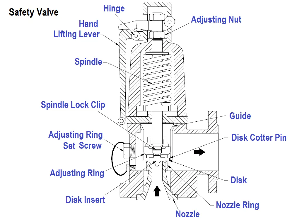
The relief valve operates by thRe action of spring which is determined by an operating pressure. The opening pressure of the spring can be adjusted by an adjusting screw provided on top of the relief valve. The spring acts opposite to the direction of the pressure and thus during normal operation of the machinery, the spring tension will not allow the valve to operate.
When the pressure acting on the valve seat increases to above normal and equalizes with the force of the spring acting downwards, the relief valve will lift and release the excessive pressure until a level of equilibrium is reached.
The lifting pressure of the valve can vary from 8~15% of the working pressure for unfired system, but also depends on manufacturers recommendations. As soon as the pressure of the system becomes normal, the spring which was set to lift at a particular pressure will close the valve as a result of the spring tension and the machinery or system will retain its normal operation.
From safety point of view, valves are constructed to have a full lift to release the excessive pressure when the system is continuously operating in overpressure situation. Such types of valves are called safety valve and relief valve falls in the same category.
Moreover, various safety codes and standards are written for controlling the design and application of the relief valve so that even after failure of other safety systems, relief valve will operate to avoid any catastrophe.
The relief valve is a critical part of the safety system which is integrated in the ship’s machinery; hence their designing is kept as simple as possible using materials of compatible strength which can operate in various conditions such as high temperature, air flow, fluid flow, corrosive media etc.
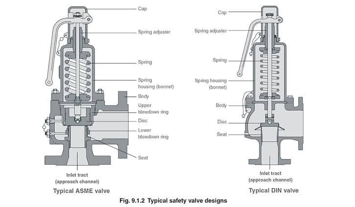
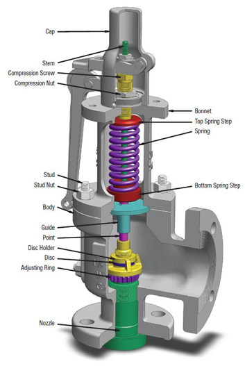
The body of the relief valve is normally made up of cast steel. It incorporates all the parts like valve spindle, valve, spring, seat etc. It must be strong enough to withstand the high pressure when valves open to release the excessive pressure through the body.
The relief valve inlet is connected to the machinery or system and its outlet connection can be open to atmosphere near to the system only in case of air system, driven through a duct outside the engine room normally for steam system or connected to the inlet or to some reservoir for hydraulic system.
The diaphragm act as a seal between the inlet outlet connection and valve body so that media should not leak through the valve body when relief valve operates.
The seat must be soft enough so that it should not damage the valve and durable enough for higher operating life else the media for which the valve is used will leak. The seat is normally made of stainless steel coated with soft metal to tackle pressure and corrosion together.
The valve plays an important role for controlled operation of the relief valve and its malfunction will lead to leakage of media from the machinery or system. It is normally made of stainless steel.
The spindle/plunger also known as valve stem has a valve attached at the bottom and the spring acts on top of it. The force exerted by spring is transferred to the valve through spindle. The material used for spindle is stainless steel.
The helical spring should have proper elasticity strength so that the valve seat can open and close at correct set pressure. Adjusting bolts are located on the top of the body. By rotating the screw the lifting pressure of the valve can be adjusted. The adjusting screw and the spring are generally made of steel alloy.
The chemical properties of the fluid should be considered before determining the best materials for your application. Each fluid will have its own unique characteristics and may reacts differently with different metal and materials. so care must be taken to select the appropriate body and seal materials that will come in contact with the fluid. The parts of the pressure relief valve which will come in contact with the fluid are termed as the “wetted” components. It is important to select correct valve material and design appropriate piping for a flammable or hazardous nature fluid.
As discussed in above point, fluid property and application will determine the selection of material for the pressure releif valves. Common pressure relief valve component materials include brass, aluminum and various grades of stainless steel. Springs used inside the relief valve acting as the driving component of the valve are typically made of carbon steel or stainless steel. Brass is also used in common application and it is cheaper. Where thereis a constraint of wight, aluminium can be used depending upon the type of fluid the pressure relief valve will handle. For hazardous and corrosive fluids, stainless steel agrades are popular choice. They also operate well when the operating temperatures is high.
Once the relief valve is lifted, how much pressure must be released from the system is determeind by the flow requirements known as flow rate. Piping arrangements, porting configuration and effective orifices are designed based on flow rate requirement.
In many applications space and weight are limitng factors. For e.g. even a high pressure machinery like air compressor will reuire small size pressure relief valve compare to other machinery having bigger valve with less pressure relief requirement. It is also important to carefully consider the port (thread) sizes, adjustment styles, and mounting options as these will influence size and weight.
The materials selected for the pressure relief valve not only need to be compatible with the fluid but also must be able to function properly at the expected operating temperature. The primary concern is whether or not the elastomer chosen will function properly throughout the expected temperature range. Additionally, the operating temperature may affect flow capacity and/or the spring rate in extreme applications.
An ardent sailor and a techie, Anish Wankhede has voyaged on a number of ships as a marine engineer officer. He loves multitasking, networking, and troubleshooting. He is the one behind the unique creativity and aesthetics at Marine Insight.
opening the valve in response to a control signal. A safety valve ismeantto relieve pressure without operator assistance and a safety valve, or combination of safety valves, must be have a capacity to relieve more than the

If you ended up on this page doing normal allowed operations, please contact our support at support@mdpi.com. Please include what you were doing when this page came up and the Ray ID & Your IP found at the
Industry leading pressure and safety relief valve designs with over 140 years of technical and application expertise providing custom engineered solutions for O&G, Refining, Chemical, Petrochemical, Process and Power applications. Our designs meet global and local codes and standards (API 526; ASME Section I, IV & VIII; EN ISO 4126; PED & more). Gain insight into the performance of your pressure relief valves with wireless monitoring.

The National Board of Boiler & Pressure Vessel Inspectors is an organization comprised of chief inspectors from various states and territories of the US and Province and territories of Canada. The primary mission is to promote public safety.
The NBIC provides rules, information, and guidance to manufacturers, Jurisdictions, Inspectors, owner-users, installers, contractors, and other individuals and organizations performing or involved in post-construction activities, thereby encouraging the uniform administration of rules pertaining to pressure retaining items.
We sat down to ask a few clarifying questions with our very own Marianne Brodeur, who was the owner of International Valve and Instrument (IVI), before its purchase by Collins in October of 2019. She also sits on the National Board as Chairperson of the subcommittee on Pressure Relief Devices. IVI has held a VR stamp for the last 34 years.
With an ever-increasing focus on reducing maintenance expenditure, there is a need for safety critical equipment to function reliably. With preventative maintenance on pressure safety valves (PSVs) being one of the more significant integrity costs, increasing efficiencies in this area is important, with potential for time savings and performance improvement.
DNV’s RBI methodology involves a dual approach: with a quantitative assessment to account for random failures and a qualitative one for the system fluid-driven mechanisms.
The change in risk from a change in interval is known and the risk from potential failure of any PSV is limited.Example: For a PSV maintained every two years, an increase from two to three years cannot be considered without knowing how the PSV performed at the two-year interval. In the worst case, with the PSV subject to a time-dependent failure mechanism, there may be a relatively high probability of failure at two years meaning that on a three-year interval, the PSV would be inoperable for a year and the equipment unprotected from a pressure excursion. With proof of successful pre-overhaul pop (pre-pop) tests at 2 year intervals, an increase in maintenance interval may be justified.
The Pressure Safety Valve Manager digital tool is client-accessible and contains all the information used in the RBI, including the (pre-pop) results. Detailed tabs contain the PSV performance history for the asset(s). The tool may also communicate with the operator’s computerized maintenance management system (CMMS) to accurately relay, not only the performance history of each PSV, but also information useful for maintenance planning, such as shutdown requirements, online testing capabilities etc.

For more than 40 years, the safety record of the global LNG industry has been excellent, due to attention to detail in engineering, construction, and operations. While the safety of processing and handling LNG has always been paramount, it is now even more important to retain this excellent record as LNG installations are getting smaller, therefore multiplying and being constructed closer to populous areas. The reliability and dependability of pressure safety valves (PSVs) protecting these installations is more critical than ever
To avoid this danger, balanced bellows safety valves are commonly used across all industries. A metallic bellows is mounted on top of the disc of the valve to protect it from the header backpressure, so the safety valve opens at the correct pressure, whatever the variations of the header pressure.
For this to work properly, the volume inside the bellows, connected to the bonnet of the valve, must be freely vented to the atmosphere, which is accomplished via a vent in the bonnet. As a result, only atmospheric pressure acts on the bellows, on top of the disc and around the spindle and guide. As these parts cool down with the process temperature—which can be as low as -260ºF (-162ºC) on LNG processes—the air moisture will condense and freeze at the lowest point: inside the bellows on top of the disc (Figure 1). This is dangerous—and invisible. As the ice builds up slowly, the disc will be blocked from opening, without this being visible from the outside, thus, the equipment is no longer protected.
Many standards refer to this situation. For example, API Standard 520 part 1, clause 4.2.1.3.9 reads: “[…] the bonnet of a balanced PRV shall be vented to atmosphere at all times. The user should be cautioned of the potential for freezing of atmospheric moisture inside the bonnet.”
This is why, since the late 1960s, pilot-operated safety valves (POSV) have been used extensively on LNG installations onshore as well as on LNG tanker ships.
POSVs use the system pressure as a closing force so that the seat tight- ness is at its maximum close to the set pressure—completely opposite from a spring-loaded valve. With the addition of a properly engineered soft seat, the tightness on cold or cryogenic service will be reinforced to avoid any leakage or even icing risk, while reducing maintenance costs.
There are several factors to consider when installing a POSV on a cold or cryogenic application. The valve and its pilot must be specifically designed to perform in these demanding cryogenic applications: Use of a standard design with all parts in austenitic stainless steel is obviously not sufficient.
Particularly, the pilot must be relatively isolated from the cryogenic temperatures. There are many proven ways of achieving this. One way, which must not be overlooked on site, is that while the main valve can usually be insulated like its associated piping, the pilot and tubing must be kept out of the insulation, in the open air.
The pilot should be non-flowing to limit the input of cryogenic media through it. A non-flowing pilot will still flow a little but only to reclose the valve: It does not flow while the main valve is opened and flowing. To reclose the main valve, the non-flowing pilot will then send process fluid into the dome of the main valve—the volume on top of the main valve piston. By re-pressurizing the dome, the piston moves down and re-closes the valve. So, the non-flowing pilot will flow only the dome volume at each open-close cycle. But a flowing pilot will flow as long as the main valve itself is opened. With such a large amount of cryogenic fluid passing through, the pilot may freeze and lock open and not be able to reclose the main valve after an event.
Until 20 years ago, the only suitable pilot technology for these applications was the snap-acting pilot, which has only two discrete positions: fully closed or fully opened. In a similar way to spring-loaded safety valves, the POSV with a snap-acting pilot will discharge its full capacity every time it opens, whatever the real needs of the protected system, leading to unnecessary heavy losses of products to flaring.
Furthermore, the snap-acting pilot itself cannot be balanced against backpressure, so any release of natural gas from the pilot must be to the atmosphere, which is dangerous and harmful.
Being truly modulating they also control the valve opening exactly in proportion to the needs of the system: important reduction of emissions as the valve will release only the strict amount of gas necessary to keep the pressure within safe limits. At the same time, this obviously eliminates the risk of oversizing and the dangerous PSV instability it can bring (Figure 2).
These pilots will also be non-flowing to reduce the amount of cryogenic fluid passing through. As the opening of the main valve is always proportional to the needs of the protected system, they typically will never need to open fully, reducing even further the volume of process fluid needed to reclose the valve at each cycle.
On liquefied gas processes, most safety valves applications will develop a mixed-phase flow as the liquefied gas flashes into vapor across the nozzle of the valve. Mixed-phase applications like these are very demanding on PSVs, causing a high amount of backpressure, additional instability on the valve and difficult reclosing. True modulating pilots have shown to be a reliable, safety valve technology for mixed-phase flows, keeping the main valve stable, even with this high level of backpressure and whatever the flashing mix; they are able to reclose the valve within the usual limits as such pilots react only on static pressure.
True modulating pilot-operated safety valves, with dedicated design and configuration for cryogenic services, offer numerous advantages for efficient and reliable pressure protection of LNG installations.
While conventional spring-loaded safety valves can provide an acceptable level of protection—particularly when fitted with a soft seat of proven design—the balanced bellows spring-loaded valves represent the potential for highly hazardous situations and should be avoided on cold or cryogenic services.
Pressure safety valves act as safeguards to protect the integrity of expensive equipment, and doing so, the lives of people and the environment. Because LNG installations are safely designed and operated, most will probably never experience the opening of a safety valve. However, it is important the design and configuration of such safety valves is correctly adapted to the process conditions.
As the supply of LNG to retail market grows, it is imperative the level of care and custody that the historical LNG industry has provided be maintained by all retail LNG market participants. Industry knowledge, and the collective lessons learned of the broader LNG industry, need to be shared with new entries.
2American Petroleum Institute, API 520: Sizing, Selection, and Installation of Pressure-relieving Devices - Part 1: Sizing and Selection, 10th edition, October 2020
Jean-Paul Boyer is process director PRV, Europe, for Emerson Automation Solutions. Boyer is a former merchant marine engineer officer and has worked with safety valves for more than 30 years. His main areas of expertise are the use of safety valves for cryogenic services and mixed phase flows.
While presenting in a recent VMA Valve Basics 101 Course in Houston, I found myself in a familiar role: explaining solenoid valves (SOVs) to attendees. (I work with solenoids so much that one VMA member at that conference joked that I needed to be wearing an I Heart Solenoids t-shirt). During the hands-on “petting zoo” portion of the program, which involves smaller groups of attendees, one of the most frequently asked questions I get from people came up: What’s the difference between direct-acting and pilot-operated SOVs, and how do we make a choice?


 8613371530291