
electric downhole safety valve price
Halliburton provides proven, high-performance tubing-retrievable and wireline-retrievable subsurface safety valves (SSSV) designed to reliably shut-in (fail safe) if a catastrophic event occurs, allowing operators to maintain safe operations.

In the search for energy, new technologies bring added benefits. These new technologies are driven by the need to be more environmentally conscious, reduce costs, increase reliability, reach farther and deeper, and provide more and better data to more effectively manage wells and equipment. With these new technologies, the industry is making a steady transition toward electrification and digitalization of the well completion. Electrification of completion equipment has occurred at a steady pace for several years, but the pace has quickened as the reliability of equipment has improved and the benefits of additional data have been realized. Within the last few years, the first completions with all-electric Christmas trees (XT) were run. Because all-electric tubing retrievable downhole safety valves were not yet available, these were not true all-electric completions. These first wells required the XTs to be installed with hydraulically operated downhole safety valves, making these mixed-technology completions. Recently, an all-electric tubing retrievable downhole safety valve was developed, qualified, and field tested. The introduction of the all-electric tubing retrievable downhole safety valve will bring the benefits of an all-electric completion to the oil industry.
All-electric tubing retrievable downhole safety valves, also known as electric surface-controlled subsurface safety valves (ESCSSV), build upon field proven technology, but offer the added benefits that an electrically operated tool can provide while performing the same critical function as the traditional hydraulic downhole safety valve.
This paper describes the development and deployment of the ESCSSV; it includes discussions about the qualification program of the valve and valve systems, integration with the all-electric subsea XT and control system, and installation in the well.

Surface-controlled subsurface safety valves (SCSSVs) are critical components of well completions, preventing uncontrolled flow in the case of catastrophic damage to wellhead equipment. Fail-safe closure must be certain to ensure proper security of the well. However, this is not the only function in which it must be reliable—the valve must remain open to produce the well. Schlumberger surface controlled subsurface safety valves exceed all ISO 10432 and API Spec 14A requirements for pressure integrity, leakage acceptance criteria, and slam closure.
Through decades of innovation and experience, Schlumberger safety valve flapper systems are proven robust and reliable. The multizone dynamic seal technology for hydraulic actuation of subsurface safety valves is a further improvement in reliability performance when compared with traditional seal systems in the industry.
The multizone seal technology is currently available in the GeoGuard high-performance deepwater safety valves, which is validated to API Spec 14A V1 and V1-H.
Baker Hughes’s portfolio of subsurface safety valves deliver reliable performance when it matters the most, providing emergency closure in the event that well control is lost. We offer a full range of valves to suit applications ranging from shallow- to deep-set, and the valves are available in surface- and subsurface-controlled, tubing-retrievable, and wireline-retrievable options. All Baker Hughes valves undergo stringent prototype testing and conform to standards and specifications such as API and ISO, as well as requirements requested for your unique situation.

Ensure high-rate production in your big bore, gas production, and high-flow-rate applications with the Onyx™ tubing retrievable subsurface safety valve from Baker Hughes.
This surface-controlled safety valve combines a sophisticated, patented closure mechanism and premium housing threads to produce the industry’s first tubing-retrievable safety valve (TRSV) with full-opening production in smaller casing sizes. These design features give you the benefits of:
The Onyx valve also gives you broader application coverage while running capillary lines for downhole instrumentation or chemical injection, and cables for electric submersible pump operation. You can also install dual completions.
The Onyx valve incorporates a nonelastomeric dynamic seal assembly that operates reliably at pressures and temperatures exceeding 28,000 psi (1,930.5 bar) and 450°F (232°C). And the valve’s RBT housing seals and two-step metal-to-metal sealing system ensure reliable strength and sealing capabilities under the most extreme conditions.

Aberdeen-based oil and gas production technology business Pragma said it has developed an advanced downhole safety valve to create an improved well control solution for cable deployed Electric Submersible Pumps (ESPs) retrofitted to production wells.
The new valve will enable on and offshore installations to meet all safety regulations while improving the operational footprint at the wellsite during installation and retrieval by reducing time, cost, personnel and risk.
An API 14A qualified subsurface safety valve (SSSV) is a legal requirement for producing wells in many regions. These devices generally use a flapper style mechanism and are incorporated in the production tubing during completion. However, when an ESP is retrofitted to a well, its surface control lines run through the inside of the production tubing, obstructing the SSSVs and creating the requirement for an additional safety valve. A rig would usually be mobilized to deploy the valve and then the ESP in separate runs, however cable deployment now provides significant cost and efficiency savings.
Pragma said its ESP safety valve has been designed to complement this type of deployment. It is a compact device, integrated within the lower portion of the ESP assembly and is deployed and retrieved through the production tubing in the same run as the ESP. It is the only device on the market which offers wellbore closure below the ESP control lines, the developer said. By installing the valve between the ESP and ESP packer, the valve does not rely on the integrity of aged well completion components unlike alternative systems.
The valve’s functionality is based on a novel pressure differential, or lift actuated design, requiring no pressurized chambers, hydraulic control lines or electrical power, which safeguards reliability. The valve will fail-safe close when the ESP is switched off and can be opened and closed as many times as required. The technology can also be applied to alternative artificial lift systems including capillary strings, gas lift velocity strings, progressive cavity pump and jet pump systems. A high temperature version is also available.
Pragma Technology Manager, Matt Manning, said, “Like a demand valve, or pressure regulator between the tank and mouthpiece of deep-sea diving equipment, our valve uses the ESP’s lifting capability to open or close it in line with production. The unique design advantages of this technology, combined with its compact nature, not only provide greater safety and reliability assurances to the operator, but also lower installation, operation and retrieval costs. The technology has been developed in-house and we are conducting prototype testing, with field trials and API 14A certification planned later this year.
“As the oil and gas industry continues to evolve, it’s important the supply chain also adapts to deliver quality solutions to support cost reduction and production optimization. The ESP safety valve is just one example of how Pragma continues to pioneer advanced technologies to deliver safety and efficiency gains.”
SSSV: Subsurface Safety Valve: a valve installed in the tubing down the well to prevent uncontrolled flow in case of an emergency through the tubing when actuated. These valves can be installed by wireline or as an integral part of the tubing. Subsurface Valves are usually divided into the following categories.
SCSSV: Surface-Controlled Subsurface Safety Valves: SSSV which is controlled from the surface and installed by wireline or as an integral part of the tubing.
SSCSV (storm choke): Subsurface-Controlled Subsurface Safety Valve: SSSV which is actuated by the flow characteristics of the well, and is wireline retrievable.
ASV: Annulus Safety Valve: a valve installed in the well to prevent uncontrolled flow in the casing-tubing annulus when actuated. It consists of an annular safety valve packer with a by-pass. The opening in the by-pass is controlled by a safety valve, which can be an integral part of the packer on a wireline retrievable valve.
The tubing safety valve is installed to provide a flow barrier in the production tubing string, between the tail pipe and the surface or mudline. Such a valve consists of 3 main items:
Safety valve should not be considered as an extra barrier in the tubing when the well is closed-in for a long period of time. Sealing is not optimal because of design space limitations. They should not be used to regularly shut-in the well.
The annulus safety valve (ASV) provides a flow barrier in the casing-tubing annulus. It consists of an annular safety valve packer with a by-pass. The opening of the by-pass is controlled by a safety valve, which can be an integral part of the packer or a wireline retrievable valve. It is a surface controlled, fail-safe closed device for annular flow.
In general, the ASV is installed in gas lifted wells where the annulus is filled with compressed gas and serves as a barrier. Because of gas lift valves, the tubing cannot be considered as a barrier between the reservoir and the surface. Although the gas lift valves are commonly equipped with check valves, they are not a valid barrier. The ASV is normally located at a shallow depth to reduce the volume of the gas stored in the annulus between the ASV and the wellhead.
The valve body and connections should be at least as strong as the tubing. It should provide leak resistance to internal and external pressures and be compatible with the fluids.
During the installation of the tubing string, it is necessary to keep the valve open. This can be done by inserting a retrievable lock-open tool in the valve, without or in combination with the control signal from surface.
Multiple zone completions, where wireline jobs are frequent on equipment installed beneath the safety valve. The larger bore of a TR-SSSV facilitates the operations, where a WR-SSSV normally has to be retrieved.
The wireline retrievable safety valve (WR SCSSV) is run on wireline. A lock mandrel is screwed on top of the WR SCSSV that enables using a landing nipple. This nipple must hold the valve/mandrel assembly against pressure differentials loads. The nipple has a polished bores to seal the path between WR SCSSV and landing nipple by seals fitted to the outside of the valve/mandrel assembly.
With hydraulically operated WR SCSSVs, the external seals have also the function of containing the control fluid that is to be transmitted to the valve actuator.
The landing nipple for an electrically operated valve has a connection for an electric control line and an inductive coupler to transmit the signal to the WR SCSSV.
Trough Flowline retrievable safety valves use specially constructed mandrels and landing nipples. They must have a stronger hold-open force than SCSSVs, because the Trough Flowline tools are circulated upwards in the tubing string, which tends to drag the valve"s flow tube up, causing the valve to close. To overcome this problem the actuator hold-open force should be higher than the sum of the normal hold open force and the drag forces that can be experienced. Trough Flowline retrievable SSSVs can be used for subsea completions where wireline operations are difficult.
Another application is to install a SSSV in tubing without a landing nipple. Such a system consists of a production packer with an integral safety valve. The assembly is positioned by the coiled tubing and the packer is set by pressure from the coiled tubing.
Subsurface controlled valves are normally open and are designed to close with an abnormal change in well condition. They detect the flow or well pressure and close when the set limit is reached. Basically there are three different concepts:
Surface controlled valves utilise valve elements that are normally closed. This fail-safe mode requires that the valve is to be opened by a hydraulic control-line pressure. Loss of this pressure will result in the closing of the valve by a spring. The hydraulic pressure is supplied from a surface control panel to the valve and acts on the actuator. Typical for hydraulic operated SCSSVs is the hydrostatic head pressure, generated by the vertical column of control fluid, which additionally acts on the valve actuator.
the surface control line pressure and the time for valve operation will give an indication whether the valve opening and closing performance is satisfactory;
TR-SCSSVs of which the hydraulic actuator is damaged can be put back into function by inserting a back-up valve (insert valve), which can be operated with the existing hydraulic control system;
Electrically operated SCSSVs have in common with hydraulic SCSSVs that the differential pressure over the closed valve must be equalised before the valve can be opened and a means to keep the valve open must be permanently available from surface for fail safe operation.
With electric valves that means is an electrical signal, either dc or ac. Loss of this signal will result in closing of the valve. The force to close is always provided by expanding steel springs, which are precompressed by either electric power or by the well pressure.
One type of mechanically operated SSSV is the Go-Devil valve from Otis. This safety valve is a normally open valve. It is designed to close by an impact force on the head of the valve, provided by a heavy ball that is dropped from a ball-dropper assembly at surface. The impact force will activate the spring based mechanical linkage, that moves the valve to the closed position.
The ball-dropper assembly is flange mounted on top of the Christmas tree. The pocket of the ball dropper retains the ball, sized to activate the Go-Devil SSSV by falling against flow and impacting the head of the valve. The ball dropper assembly retains the ball until the loss of the control signal activates the release mechanism.
Three types of valve closure elements are commonly used for SSSV: the ball, the flapper and the poppet type. The flapper valve can further be divided in flat, contoured and curved flappers, while the poppet valve can be divided into closed body and sleeve type poppet valves. All types of closure elements pinch off the fluid stream by a pair of opposing surfaces rather than sliding surfaces. This principal method has the advantage that it can provide a good tight shut-off when the sealing surfaces are sound.
As noted the flapper valves may be flat, curved or contoured. The latter two were introduced to obtain a better OD/ID ratio, as they are shaped to fit when in the open position, more efficiently in the annular space of the valve housing.
The seat angle is the shape of the flapper sealing surfaces, which is an important parameter of the valve sealing performance. Traditional flapper valves have a seat angle of 45°, as the angled seat has the advantage that:
Due to the characteristics of the curved flapper design the seat angle may vary from 0° to 60° along the flapper circumference, thus requiring stringent alignment of the sealing faces. The contoured flapper design has an angled sealing surface over the full circumference of the flapper and thus has potential to provide good sealing. Field experience indicate that the flapper valve type is more reliable than the ball valve type.
When a SSSV is closed, a high differential pressure may be present across the valve closure element. Opening the valve under this condition will be difficult, if not impossible, because of the incapability of the relatively small valve mechanism to cope with the load working on the large diameter closure element. Insufficient equalising will introduce high loads that could deform critical valve parts. Also, erosive wash-out on the closure element by the sudden rush of well fluid through the partly opened valve can occur. Therefore, prior to opening a SSSV it is necessary to equalise the differential pressure.
The depth at which to set the subsurface safety valve depends upon a number of variables, such as hydrate and wax formation tendencies, deviation kick-off depth, scale precipitation, earthquake probabilities, etc. The OD of the safety valve may influence the casing/tubing string configuration and should be addressed at the conceptual design stage.
For tubing safety valves it is obvious that the deeper the valve is set (closer to the hydrocarbon source) the more protection it will give to the completion. However, the application of a deep-set tubing SSSV generates some unfavourable conditions, namely:
the higher temperature further downhole effects the reliability and the longevity of non-metal valve parts, for instance polymeric seals in hydraulic valves and electric/electronic parts in electric valves;
the hydrostatic head pressure generated by the hydraulic control-line column will generate excessive forces on the valve operating mechanism. Hence, designing and manufacturing of these valves becomes more complicated.
Furthermore, the required control pressure to operate a single control line valve (the majority of SSSVs) could become too high and more than the pressure rating of standard well completion equipment.
The approach for determining the required hydraulic control pressure at surface to hold a valve open depends on the type of valve, viz. the single control line valve, the dual control line valve and the valve with a pressure chamber.
Due to friction in the valve mechanism and the spring characteristic, there is a certain spread between the valve opening pressure (Pvo) and closing pressure (Pvc).
To ensure that the valve is completely open, a safety factor or pressure margin (Pm) is added to the surface control pressure. Hence, the available control pressure at surface to open the valve must be at least:
The dual control line valve or the pressure balanced valve uses a second control line from surface to balance the generated hydrostatic head pressure in the control line. The forces acting to operate this type of valve are as follows:
Due to friction in the valve mechanism and the spring characteristic, there is a certain spread between the valve opening pressure (Pvo) and closing pressure (Pvc).
When the valve is in the fully open position and the control and the balance line are both filled with fluid of the same fluid gradient, the following force equilibrium exists:
To insure that the valve is completely open, a safety factor or pressure margin (Pm) is added to the surface control pressure. Hence, the available control pressure at surface to open the valve must be at least:
The dome charged valve uses a pressure in an integral dome to (partly) balance the generated hydrostatic head pressure in the control line. The forces acting to operate this type of valve are as follows:
Due to friction in the valve mechanism and the spring characteristic, there is a certain spread between the valve opening pressure (Pvo) and closing pressure (Pvc).
To ensure that the valve is completely open, a safety factor or pressure margin (Pm) is added to the surface control pressure. Hence, the available control pressure at surface to open the valve must be at least:
The theoretical maximum setting depth of a single control line SSSV depends on the capacity of the valve closing spring to overcome the generated hydrostatic head pressure in the control line. For fail safety it is essential that the tubing pressure is not taken into account for the assistance of valve closing, even though single control line valves are assisted by this pressure. Hence, the governing factors for the maximum valve setting depth are:
* For fail safety, the worst case must be assumed, one in which the control line ruptures near the valve and annulus fluid will enter the control line. Therefore, for any completion the heaviest fluid gradient, either from the control fluid or from the annulus fluid, is used as the minimum control line fluid gradient.
Because the hydrostatic head pressure in the control line is counteracted, the setting depths of the dual control-line and the dome-charged valves are theoretically not limited.
This invention relates in general, to the operation of a subsurface safety valve installed in the tubing of a subterranean wellbore and, in particular, to an apparatus and method for locking out a subsurface safety valve and communicating hydraulic fluid through the subsurface safety valve.
One or more subsurface safety valves are commonly installed as part of the tubing string within oil and gas wells to protect against unwanted communication of high pressure and high temperature formation fluids to the surface. These subsurface safety valves are designed to shut in production from the formation in response to a variety of abnormal and potentially dangerous conditions.
As these subsurface safety valves are built into the tubing string, these valves are typically referred to as tubing retrievable safety valves ("TRSV"). TRSVs are normally operated by hydraulic fluid pressure which is typically controlled at the surface and transmitted to the TRSV via a hydraulic fluid line. Hydraulic fluid pressure must be applied to the TRSV to place the TRSV in the open position. When hydraulic fluid pressure is lost, the TRSV will operate to the closed position to prevent formation fluids from traveling therethrough. As such, TRSVs are fail safe valves.
As TRSVs are typically incorporated into the tubing string, removal of the tubing string to replace or repair the malfunctioning TRSV is required. As such, the costs associated with replacing or repairing the malfunctioning TRSV is quite high. It has been found, however, that a wireline retrievable safety valve ("WRSV") may be inserted inside the original TRSV and operated to provide the same safety function as the original TRSV. These insert valves are designed to be lowered into place from the surface via wireline and locked inside the original TRSV. This approach can be a much more efficient and cost-effective alternative to pulling the tubing string to replace or repair the malfunctioning TRSV.
It has been found, however, that operating conventional TRSVs to the locked out position and establishing this communication path has several inherent drawbacks. To begin with, the inclusion of such built-in lock out sleeves in each TRSV increases the cost of the TRSV, particularly in light of the fact that the built-in lock out sleeves are not used in the vast majority of installations. In addition, since these built-in lock out sleeves are not operated for extended periods of time, in most cases years, they may become inoperable before their use is required. Also, it has been found, that the communication path of the pre-machined radial bore creates a potential leak path for formation fluids up through the hydraulic control system. As noted above, TRSVs are intended to operate under abnormal well conditions and serve a vital and potentially lifesaving function. Hence, if such an abnormal condition occurred when one TRSV has been locked out, even if other safety valves have closed the tubing string, high pressure formation fluids may travel to the surface through the hydraulic line.
The present invention disclosed herein comprises an apparatus and method for establishing a communication path for hydraulic fluid to a wireline retrievable safety valve from a rod piston operated tubing retrievable safety valve. The apparatus and method of the present invention do not require a built-in lock out sleeve in the rod piston operated tubing retrievable safety valve. Likewise, the apparatus and method of the present invention avoid the potential for formation fluids to travel up through the hydraulic control line associated with a pre-drilled radial bore in the tubing retrievable safety valve.
In broad terms, the apparatus of the present invention allows hydraulic control to be communicated from a non annular hydraulic chamber of a rod piston operated tubing retrievalbe safety valve to the interior thereof so that the hydraulic fluid may, for example, be used to operate a wireline retrievable safety valve is detected and a need exists to otherwise achieve the functionality of the rod piston operated tubing retrievable safety valve.
The rod piston operated tubing retrievable safety valve of the present invention has a housing having a longitudinal bore extending therethrough. The safety valve also has a non annular hydraulic chamber in a sidewall portion thereof. A valve closure member is mounted in the housing to control fluid flow through the longitudinal bore by operating between closed and opened positions. A flow tube is disposed within the housing and is used to shift the valve closure member between the closed and opened positions. A rod piston, which is slidably disposed in the non annular hydraulic chamber of the housing, is operably coupled to the flow tube. The safety valve of the present invention also has a pocket in the longitudinal bore.
In one embodiment of the present invention a communication tool is used to establish a communication path between the non annular hydraulic chamber in a sidewall portion of the safety valve and the interior of the safety valve. In this embodiment, the communication tool has a first section and a second section that are initially coupled together using a shear pin or other suitable coupling device. A set of axial locating keys is operably attached to the first section of the tool and is engagably positionable within a profile of the safety valve. The tool includes a radial cutting device that is radially extendable through a window of the second section. For example, the radial cutting device may include a carrier having an insert removably attached thereto and a punch rod slidably operable relative to the carrier to radially outwardly extend the insert exteriorly of the second section.
The tool also includes a circumferential locating key that is operably attached to the second section of the tool. The circumferential locating key is engagably positionable within the pocket of the safety valve. Specifically, when the first and second sections of the tool are decoupled, the second section rotations relative to the first section until the circumferential locating key engages the pocket, thereby circumferentially aligning the radial cutting device with the non annular hydraulic chamber. A torsional biasing device such as a spiral wound torsion spring places a torsional load between the first and second sections such that when the first and second sections are decoupled, the second section rotates relative to the first section. A collet spring may be used to radially outwardly bias the circumferential locating key such that the circumferential locating key will engage the pocket, thereby stopping the rotation of the second section relative to the first section. Once the circumferential locating key has engaged the pocket, the radial cutting device will be axially and circumferentially aligned with the non annular hydraulic chamber. Through operation of the radial cutting device, a communication path is created from the non annular hydraulic fluid chamber to the interior of the safety valve.
As such, hydraulic fluid may now be communicated down the existing hydraulic lines to the interior of the tubing. Once this communication path exists, for example, a wireline retrievable safety valve may be positioned within the rod piston operated tubing retrievable safety valve such that the hydraulic fluid pressure from the hydraulic system may be communicated to a wireline retrievable safety valve.
In another embodiment of the present invention, a lock out and communication tool is used to lock out the safety valve and then establish a communication path between the non annular hydraulic chamber in a sidewall portion of the safety valve and the interior of the safety valve. In this embodiment, the lock out and communication tool is lowered into the safety valve until the lock out and communication tool engages the flow tube. The lock out and communication tool may then downwardly shift the flow tube, either alone or in conjunction with an increase in the hydraulic pressure acting on the rod piston, to operate the valve closure member from the closed position to the fully open position. Alternatively, if the safety valve is already in the open position, the lock out and communication tool simply prevents movement of the flow tube to maintain the safety valve in the open position. Thereafter, the lock out and communication tool interacts with the safety valve as described above with reference to the communication tool to communicate hydraulic fluid from the non annular hydraulic fluid chamber to the interior of the safety valve.
One method of the present invention that utilizes the communication tool involves inserting the communication tool into the safety valve, locking the communication tool within the safety valve with the safety valve in a valve open position, axially aligning the radially cutting device with the non annular hydraulic chamber, circumferentially aligning the radially cutting device with the non annular hydraulic chamber and penetrating the radially cutting device through the sidewall portion and into the non annular hydraulic chamber to create a communication path between the non annular hydraulic chamber and the interior of the safety valve.
In addition, a method of the present invention that utilizes the lock out and communication tool involves engaging the flow tube of the safety valve with the lock out and communication tool, retrieving the lock out and communication tool from the safety valve and maintaining the safety valve in the valve open position by preventing movement of the rod piston with an insert that is left in place within the sidewall portion when the remainder of the radial cutting tool is retracted.
Described hereinafter is a method for communicating hydraulic fluid through a tubing retrievable safety valve having a non annular chamber in a sidewall portion thereof, the method comprising the steps of: locating a communication tool within the tubing retrievable safety valve; and
creating a fluid passageway between the non annular hydraulic chamber and the interior of the tubing retrievable safety valve with the communication tool.
Ideally the step of creating a fluid passageway between the non annular hydraulic chamber and the interior of the tubing retrievable safety valve with the communication tool comprises penetrating through the sidewall portion and into the non annular hydraulic chamber. The step of locating the communication tool within the tubing retrievable safety valve may further comprise engaging locating keys of the communication tool into a profile.
The method may also comprise the step of circumferentially aligning a locating key of the communication tool with a pocket of the tubing retrievable safety valve to prevent relative rotation therebetween. Preferably, this step of circumferentially aligning a locating key of the communication tool with a pocket of the tubing retrievable safety valve further comprises radially outwardly shifting the locating key with a collet spring attached to the communication tool.
Ideally, the communication tool includes a cutting device which creates the fluid passageway between the non annular hydraulic chamber and the interior of the tubing retrievable safety valve.
The method may also comprise the step of actuating an anti-rotation mechanism to prevent rotation of at least a portion of the communication tool relative to the tubing retrievable safety valve. Ideally, actuating the anti-rotation mechanism includes shearing a shear pin coupling a portion of the cutting device to a portion of the communication tool. Also, actuating the anti-rotation mechanism may include aligning a protruding portion of the communication tool with a recessed portion of the tubing retrievable safety valve. Furthermore, actuating the anti-rotation mechanism may further include shifting the protruding portion of the communication tool radially outward to engage the recessed portion of the tubing retrievable safety valve. Also, actuating the anti-rotation mechanism may include circumferentially aligning the cutting device with the non annular hydraulic chamber.
Ideally, the step of creating the fluid passageway includes mechanically cutting the sidewall portion of the tubing retrievable safety valve. Also, the mechanically cutting step may be carried out with a mechanical cutting device preferably in the form of a punch. The cutting device may be a radial cutting device which creates a fluid passageway from the non annular hydraulic chamber to the interior of the tubing retrievable safety valve by radially penetrating through the sidewall portion and into the non annular hydraulic chamber.
Furthermore, the step of creating a fluid passageway from the non annular hydraulic chamber to the interior of the tubing retrievable safety valve by radially penetrating the radial cutting device through the sidewall portion and into the non annular hydraulic chamber may further comprise radially outwardly shifting the radially cutting device with a punch rod. Also, the step of creating a fluid passageway from the non annular hydraulic chamber to the interior of the tubing retrievable safety valve by radially penetrating the radial cutting device through the sidewall portion into the non annular hydraulic chamber may further comprise disposing an insert having a fluid passageway in the sidewall portion of the tubing retrievable safety valve.
Also described below is a system for communicating hydraulic fluid to a wireline retrievable safety valve comprising: a tubing retrievable safety valve having a non annular hydraulic chamber in a sidewall portion thereof; and
a communication tool selectively locatable within the tubing retrievable safety valve, the communication tool creating a fluid passageway between the non annular hydraulic chamber and the interior of the tubing retrievable safety valve by penetrating through the sidewall portion and into the non annular hydraulic chamber such that when the wireline retrievable safety valve is positioned within the tubing retrievable safety valve, hydraulic fluid is communicatable thereto through the fluid passageway.
Ideally, the tubing retrievable safety valve further comprises a pocket that engageably receives a locating key of the communication tool whereby the interaction between the locating key and the pocket prevents relative rotation between the communication tool and the tubing retrievable safety valve.
Also described hereinafter is a safety valve for downhole use in a well comprising: a housing having a longitudinal bore extending therethrough and having a non annular hydraulic chamber in a sidewall portion thereof, the longitudinal bore operable to receive a communication tool therein that creates a fluid passageway between the non annular hydraulic chamber and the interior of the tubing retrievable safety valve by penetrating through the sidewall portion and into the non annular hydraulic chamber;
a valve closure member mounted in the housing to control fluid flow through the longitudinal bore, the valve closure member having closed and open positions;
The longitudinal bore may be operable to receive a communication tool therein such that relative rotation between at least a portion of the communication tool and the safety valve is substantially prevented. The valve may also further comprise an anti rotation mechanism associated with the longitudinal bore. The valve may also further comprise a pocket in the longitudinal bore for engaging a locating key of the communication tool whereby the interaction between the locating key and the pocket substantially prevents relative rotation between the at least a portion of the communication tool and the safety valve.
The sidewall portion may have a radially reduced region. The valve may further comprise a profile in the longitudinal bore for engaging a set of axial locating keys of the communication tool. The valve ideally comprises a spring positioned between the housing and the flow tube that biases the valve closure member toward the closed position. The valve may also further comprise a hydraulic fluid operating against the rod piston in the non annular hydraulic chamber that biases the valve closure member toward the open piston.
For a more complete understanding of the present invention understanding of the present invention, including its features and advantages, reference is now made to the detailed description of the invention, taken in conjunction with the accompanying drawings in which like numerals identify like parts and in which: Figure 1 is a schematic illustration of an offshore production platform wherein a wireline retrievable safety valve is being lowered into a tubing retrievable safety valve to take over the functionality thereof;
Figures 2A-2B are cross sectional views of successive axial sections of a rod piston operated tubing retrievable safety valve of the present invention in its valve closed position;
Figures 3A-3B are cross sectional views of successive axial sections of a rod piston operated tubing retrievable safety valve of the present invention in its valve open position;
Figures 5A-5B are cross sectional views of successive axial sections of a communication tool of the present invention in its running position and disposed in a rod piston operated tubing retrievable safety valve of the present invention;
Figures 6A-6B are cross sectional views of successive axial sections of a communication tool of the present invention in its locked position and disposed in a rod piston operated tubing retrievable safety valve of the present invention;
Figures 7A-7B are cross sectional views of successive axial sections of a communication tool of the present invention in its orienting position and disposed in a rod piston operated tubing retrievable safety valve of the present invention;
Figures 8A-8B are cross sectional views of successive axial sections of a communication tool of the present invention in its perforating position and disposed in a rod piston operated tubing retrievable safety valve of the present invention;
Figures 9A-9B are cross sectional views of successive axial sections of a communication tool of the present invention in its retrieving position and still substantially disposed in a rod piston operated tubing retrievable safety valve of the present invention; and
Figures 10A-10C are cross sectional views of successive axial sections of a lock out and communication tool of the present invention disposed in a rod piston operated tubing retrievable safety valve of the present invention.
Referring to figure 1, an offshore oil and gas production platform having a wireline retrievable safety valve lowered into a tubing retrievable safety valve is schematically illustrated and generally designated 10. A semi-submersible platform 12 is centered over a submerged oil and gas formation 14 located below sea floor 16. Wellhead 18 is located on deck 20 of platform 12. Well 22 extends through the sea 24 and penetrates the various earth strata including formation 14 to form wellbore 26. Disposed within wellbore 26 is casing 28. Disposed within casing 28 and extending from wellhead 18 is production tubing 30. A pair of seal assemblies 32, 34 provide a seal between tubing 30 and casing 28 to prevent the flow of production fluids therebetween. During production, formation fluids enter wellbore 26 through perforations 36 in casing 28 and travel into tubing 30 to wellhead 18.
Coupled within tubing 30 is a tubing retrievable safety valve 38. As is well known in the art, multiple tubing retrievable safety valves are commonly installed as part of tubing string 30 to shut in production from formation 14 in response to a variety of abnormal and potentially dangerous conditions. For convenience of illustration, however, only tubing retrievable safety valve 38 is shown.
Tubing retrievable safety valve 38 is operated by hydraulic fluid pressure communicated thereto from surface installation 40 and hydraulic fluid control conduit 42. Hydraulic fluid pressure must be applied to tubing retrievable safety valve 38 to place tubing retrievable safety valve 38 in the open position. When hydraulic fluid pressure is lost, tubing retrievable safety valve 38 will operate to the closed position to prevent formation fluids from traveling therethrough.
If, for example, tubing retrievable safety valve 38 is unable to properly seal in the closed position or does not properly open after being in the closed position, tubing retrievable safety valve 38 must typically be repaired or replaced. In the present invention, however, the functionality of tubing retrievable safety valve 38 may be replaced by wireline retrievable safety valve 44, which may be installed within tubing retrievable safety valve 38 via wireline assembly 46 including wireline 48. Once in place within tubing retrievable safety valve 38, wireline retrievable safety valve 44 will be operated by hydraulic fluid pressure communicated thereto from surface installation 40 and hydraulic fluid line 42 through tubing retrievable safety valve 38. As with the original configuration of tubing retrievable safety valve 38, the hydraulic fluid pressure must be applied to wireline retrievable safety valve 44 to place wireline retrievable safety valve 44 in the open position. If hydraulic fluid pressure is lost, wireline retrievable safety valve 44 will operate to the closed position to prevent formation fluids from traveling therethrough.
Referring now to figures 2A and 2B, therein is depicted cross sectional views of successive axial sections a tubing retrievable safety valve embodying principles of the present invention that is representatively illustrated and generally designated 50. Safety valve 50 may be connected directly in series with production tubing 30 of figure 1. Safety valve 50 has a substantially cylindrical outer housing 52 that includes top connector subassembly 54, intermediate housing subassembly 56 and bottom connector subassembly 58 which are threadedly and sealing coupled together.
It should be apparent to those skilled in the art that the use of directional terms such as top, bottom, above, below, upper, lower, upward, downward, etc. are used in relation to the illustrative embodiments as they are depicted in the figures, the upward direction being toward the top of the corresponding figure and the downward direction being toward the bottom of the corresponding figure. As such, it is to be understood that the downhole components described herein may be operated in vertical, horizontal, inverted or inclined orientations without deviating from the principles of the present invention.
Hydraulic control pressure is communicated to longitudinal bore 60 of safety valve 50 via control conduit 42 of figure 1. A rod piston 68 is received in slidable, sealed engagement against longitudinal bore 60. Rod piston 68 is connected to a flow tube adapter 70 which is threadedly connected to a flow tube 72. Flow tube 72 has profile 74 and a downwardly facing annular shoulder 76.
A flapper plate 78 is pivotally mounted onto a hinge subassembly 80 which is disposed within intermediate housing subassembly 56. A valve seat 82 is defined within hinge subassembly 80. It should be understood by those skilled in the art that while the illustrated embodiment depicts flapper plate 78 as the valve closure mechanism of safety valve 50, other types of safety valves including those having different types of valve closure mechanisms may be used without departing from the principles of the present invention, such valve closure mechanisms including, but not limited to, rotating balls, reciprocating poppets and the like.
In normal operation, flapper plate 78 pivots about pivot pin 84 and is biased to the valve closed position by a spring (not pictured). When safety valve 50 must be operated from the valve closed position, depicted in figures 2A-2B, to the valve opened position, depicted in figures 3A-3B, hydraulic fluid enters longitudinal bore 60 and acts on rod piston 68. As the downward hydraulic force against rod piston 68 exceeds the upward bias force of spiral wound compression spring 86, flow tube 72 moves downwardly with rod piston 68. As flow tube 72 continues to move downwardly, flow tube 72 contacts flapper closure plate 78 and forces flapper closure plate 78 to the open position.
When safety valve 50 must be operated from the valve open position to the valve closed position, hydraulic pressure is released from conduit 42 such that spring 86 acts on shoulder 76 and upwardly bias flow tube 72. As flow tube 72 is retracted, flapper closure plate 78 will rotate about pin 84 and seal on seat 82.
If safety valve 50 becomes unable to properly seal in the closed position or does not properly open after being in the closed position, it is desirable to reestablish the functionality of safety valve 50 without removal of tubing 30. In the present invention this is achieved by inserting a lock out and communication tool into the central bore of safety valve 50.
The operation of communication tool 100 of the present invention will now be described relative to safety valve 50 of the present invention with reference to figures 5A-5B, 6A-6B, 7A-7B, 8A-8B and 9A-9B. In figures 5A-5B, communication tool 100 is in its running configuration. Communication tool 100 is positioned within the longitudinal central bore of safety valve 50. As communication tool 100 is lowered into safety valve 50, downwardly facing annular shoulder 154 of main mandrel 132 contacts profile 74 of flow tube 72. Main mandrel 132 may downwardly shift flow tube 72, either alone or in conjunction with an increase in the hydraulic pressure within longitudinal chamber 60, operating flapper closure plate 78 from the closed position, see figures 2A-2B, to the fully open position, see figures 3A-3B. Alternatively, if safety valve 50 is already in the open position, main mandrel 132 simply holds flow tube 72 in the downward position to maintain safety valve 50 in the open position. Communication tool 100 moves downwardly relative to outer housing 52 of safety valve 50 until axial locating keys 112 of communication tool 100 engage profile 62 of safety valve 50.
Once axial locating keys 112 of communication tool 100 engage profile 62 of safety valve 50, downward jarring on communication tool 100 shifts fish neck 124 along with fish neck mandrel 126, fish neck mandrel extension 128, upper mandrel 116 and expander mandrel 118 downwardly relative to safety mandrel 50 and punch rod 130. This downward movement shifts expander mandrel 118 behind axial locating keys 112 which locks axial locating keys 112 into profile 62, as best seen in figures 6A-6B.
In this locked configuration of communication tool 100, dogs 122 are aligned with radially reduced interior section 106 of upper housing subassembly 104. As such, additional downward jarring on communication tool 100 outwardly shifts dogs 122 which allows fish neck mandrel extension 128 to move downwardly. This allows the lower surface of fish neck 124 to contact the upper surface of punch rod 130. Continued downward jarring with a sufficient and predetermined force shears pins 136, as best seen in figures 7A-7B. When pins 136 shear, this allows punch rod 130 and main mandrel 132 to move axially downwardly relative to housing 102 and expander mandrel 118 of communication tool 100 and safety valve 50. This downward movement axially aligns carrier 146 and insert 148 with radially reduced area 64 and axially aligns circumferential locating key 140 with pocket 66 of safety valve 50.
In addition, when pins 136 shear, this allows punch rod 130 and main mandrel 132 to rotate relative to housing 102 and expander mandrel 118 of communication tool 100 and safety valve 50 due to the torsional force stored in torsion spring 138. This rotational movement circumferentially aligns carrier 146 and insert 148 with longitudinal bore 60 of safety valve 50. This is achieved due to the interaction of circumferential locating key 140 and pocket 66. Specifically, as punch rod 130 and main mandrel 132 rotate relative to safety valve 50, collet spring 142 radially outwardly biases circumferential locating key 140. Thus, when circumferential locating key 140 becomes circumferentially aligned with pocket 66, circumferential locating key 140 moves radially outwardly into pocket 66 stopping the rotation of punch rod 130 and main mandrel 132 relative to safety valve 50. By axially and circumferentially aligning circumferential locating key 140 with pocket 66, carrier 146 and insert 148 become axially and circumferentially aligned with longitudinal bore 60 of safety valve 50.
Once carrier 146 and insert 148 are axially and circumferentially aligned with longitudinal bore 60 of safety valve 50, communication tool 100 is in its perforating position, as depicted in figures 8A-8B. In this configuration, additional downward jarring on communication tool 100, of a sufficient and predetermined force, shears pin 134 which allow punch rod 130 to move downwardly relative to main mandrel 132. As punch rod 130 move downwardly, insert 148 penetrates radially reduced region 64 of safety valve 50. The depth of entry of insert 148 into radially reduced region 64 is determined by the number of jars applied to punch rod 130. The number of jars applied to punch rod 130 is predetermined based upon factors such as the thickness of radially reduced region 64 and the type of material selected for outer housing 52.
With the use of communication tool 100 of the present invention, fluid passageway 150 of insert 148 provides a communication path for hydraulic fluid from longitudinal bore 60 to the interior of safety valve 50. Once insert 148 is fixed within radially reduced region 64, communication tool 100 may be retrieved to the surface, as depicted in figures 9A-9B. In this configuration, punch rod 130 has retracted from behind carrier 146, fish neck mandrel extension 128 has retracted from behind keys 106 and expander mandrel 118 has retracted from behind axial locating keys 112 which allows communication tool 100 to release from safety valve 50. Insert 148 now prevents the upward movement of rod piston 68 and flow tube 72 which in turn prevents closure of flapper closure plate 78, thereby locking but safety valve 50. In addition, flow passageway 150 of insert 148 allow for the communication of hydraulic fluid from longitudinal bore 60 to the interior of safety valve 50 which can be used, for example, to operate a wireline retrievable subsurface safety valve that is inserted into locked out safety valve 50.
In operation, as lock out and communication tool 200 is positioned within the longitudinal central bore of safety valve 50 as described above with reference to tool 100, flapper closure plate 78 is operated from the closed position, see figures 2A-2B, to the fully open position, see figures 3A-3B. Lock out and communication tool 200 moves downwardly relative to outer housing 52 of safety valve 50 until axial locating keys 212 of lock out and communication tool 200 engage profile 62 of safety valve 50 and are locked therein.
In this locked configuration of lock out and communication tool 200, shears pins 236 may be sheared in response to downward jarring which allows punch rod 230 and main mandrel 232 to move axially downwardly relative to housing 202 and expander mandrel 218 of lock out and communication tool 200 and safety valve 50. As explained above, this downward movement axially aligns carrier 246 and insert 248 with radially reduced area 64. In addition, circumferential locating key 240 is both axially and circumferentially aligned with pocket 66 of safety valve 50.
By axially and circumferentially aligning circumferential locating key 240 with pocket 66, carrier 246 and insert 248 become axially and circumferentially aligned with longitudinal bore 60 of safety valve 50 such that additional downward jarring on lock out and communication tool 200 of a sufficient and predetermined force shears pin 234 which allow punch rod 230 to move downwardly relative to main mandrel 232 and main mandrel extension 260. As punch rod 230 move downwardly, insert 248 penetrates radially reduced region 64 of safety valve 50. Further travel of punch rod 230 downwardly relative to main mandrel 232 and main mandrel extension 260 causes dimpling member 268 to contact and form a dimple in the inner wall of safety valve 50 which prevents upward travel of piston 68 after lock out and communication tool 200 is retrieved from safety valve 50.
The unique interaction of lock out and communication tool 200 of the present invention with safety valve 50 of the present invention thus allow for the locking out of a rod piston operated safety valve and for the communication of its hydraulic fluid to operate, for example, an insert valve.

To monitor a subsurface safety valve installed in the production tubing, whose function is to stop the well production in case of destruction of surface equipment (particularly well head and X mass tree equipments).
This monitoring is realized by electro-magnetic data transmission system, eliminating all physical link from downhole to the surface (electric cable, or hydraulic control line subject to deterioration and leaks, and limited in depth to 300 meters).
This system allows to install a subsurface safety valve at a greater depth (more than 1000 meters without problem) and also in already existing wells not equipped with nipple fed with control line. Hence reducing the volume of fluid under pressure inside the well tubing below the safety valve.
This new concept eliminates the constrains in term of complexity, time and cost due to the physical links (electrical cable or control line) attached to the commercial surface controlled subsurface safety valve existing today on the market.
The new product will be able to be installed at any depth and particularly to restore, at low cost, the safety function on wells non equipped with safety devices.
- Greater depth installation which increases safety in well operation by reducing the volume of fluids under pressure below the safety valve when closed.
Two main applications appear now due to the fact that electromagnetic transmission eliminates any physical link from downhole to surface (no electrical cable, no hydraulic control line, long to install, subject to deterioration and limited in depth to 300 meters).
- Installation in new completion of subsurface safety valve at greater depth (more than 1000 meters without problem). - Installation of subsurface safety valve in already existing wells, not equipped with nipple fed with hydraulic control line or having control line broken etc... hence restoring the safety functions in the well without being obliged to carry out costly and dangerous workover operations.
After a six months period, equipment will be pulled out of the hole for inspection of the components. Residual electrical capacity of the batteries, will be measured, in order to define electrical consumption, for a six months period, to be able to evaluate the normal operation duration. After evaluation, dissemination will be organised.
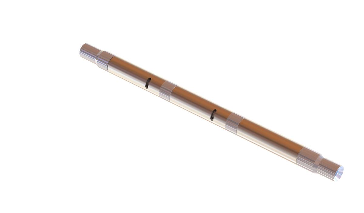
The TSS series subsurface safety valves are tubing retrievable surface controlled subsurface safety valves. Compared with the TS series, the safety valve features super slim outer diameter design. The control line connects the valve to the surface, and the pressurization from surface on the control line controls the opening and closing of the flapper. This series of products includes self-equalizing and non-equalizing types.

The invention relates to a method of operating a subsea production system, a subsea production system, a subsea tree and an electric downhole safety valve with a backup solution in case of failure.
Prior art includes fully all-electric subsea trees. One such all-electric subsea tree is disclosed in SPE Article, SPE-186150-MS, published on SPE Offshore Europe Conference & Exhibition, 5-8 September 2017, Aberdeen, United Kingdom. Here it is described that an all-electric subsea well consists of an electric subsea Christmas tree, electric downhole safety valve, and associated subsea control modules. Valve control is established via an electric cable. Umbilicals used in hydraulic subsea operations are complex, difficult to install, and highly expensive. Replacing hydraulic fluid tubes by an electric cable within the umbilical can provide a 15% cost savings over a 30-km step-out. The technology also improves control of environmental impact by removing the risk of hydraulic fluid release.
A downhole safety valve is functioning as one of the barriers in the well, and is an important element. Normally such a valve will be tested for operation at regular intervals. An electrically operated downhole safety valve would normally be equipped with an A and B (redundant) electric operation system. In the event both of these fail in providing power to the downhole safety valve, the well is shut in and cannot be reopened until power (and communication) is re-established. One possible way of alleviating this is to install two electric downhole safety valves in series within the well. For hydraulically operated trees with a hydraulic operated downhole safety valve, there are provisions for setting an in -tubing insertable hydraulically operated downhole safety valve by wireline operations, to gain the same functionalities and barriers as the non-functional production tubing installed downhole safety valve.
The downhole safety valve (DHSV) is a primary well barrier element located in the “upper” completion string and comprises a valve unit and an actuator. The purpose of the downhole safety valve is to prevent uncontrolled flow of fluids from the reservoir and up the tubing in an emergency situation by closing the valve. The downhole safety valve is also sometimes referred to as surface controlled subsea safety valve (SCSSV).
For a hydraulically operated tree, the downhole safety valve is normally a hydraulically operated valve. The two major types of hydraulic operated downhole safety valves which comprises a flapper are the tubing retrievable surface controlled subsurface safety valve (TRSCSSV) and the wireline retrievable surface controlled subsurface safety valve (WRSCSSV).
The TRSCSSV is installed as part of the tubing string with threaded connections at the upper end (box) and lower end (pin) of the valve. This concept maintains the inside diameter (ID) of the production tubing string also through the safety valve.
The backup for the TRSCSSV for a hydraulic system is the WRSCSSV, which WRSCSSV is a wireline retrievable surface controlled subsurface safety valve. The WRSCSSV is basically a smaller diameter version of the TRSCSSV with main application as through-tubing conveyed means for remediation of TRSCSSV failures. The WRSCSSV is normally installed within the TRSCSSV taking advantage of the existing hydraulic line. The WRSCSSV is also named insert hydraulic downhole safety valve (DHSV).
For an electric tree or for a tree with an electric downhole safety valve, there are no hydraulic lines down to the position of the electric downhole safety valve as there is not need for a hydraulic connection as the valve is electrically operated, i.e. there is no hydraulic present and there is no hydraulic access. In other words, for an originally installed electric downhole safety valve which is electrically operated there are no provisions in the well for providing hydraulics to the position of the electrically operated electric downhole safety valve as there are no need for hydraulics. Such a safety valve would also normally have both an A and B (redundant) operation systems.
A problem may rise in the electric subsea trees or in any tree (electric or hydraulically operable) having an original installed electric downhole safety valve, in the event that the electric access to the electric downhole safety valve is (for any reason) restricted or fully prevented so that the redundant B system of the electric system does not work as the A system is not working, hence the electric downhole safety valve does not work properly.
It is an object of the invention to provide an alternative fallback solution for a tree and well with an electrically operable electric downhole safety valve, in the case the electric downhole safety valve does not work properly.
In all embodiments, as defined in the independent apparatus claim and in the independent method claims, a hydraulically operable insert hydraulic downhole safety valve is set in a subsea production system with a X-mas tree and originally electric downhole safety valve. In one embodiment there is an electric subsea tree, also referred to as an electric tree or an all-electric subsea tree within the oil and gas industry, which is characterized in that it is electrically operated and that a traditional umbilical with a hydraulic fluid line as used in the oil and gas industry is superfluous because the operation of the valves in the electric subsea tree is done by electric communication/power only.
The production system comprises an electrically operated downhole safety valve, and since the system originally is intended to operate electrically, the system does not comprise a fluid or hydraulic line from the electric downhole safety valve to a power source on the seabed or at surface. According to the invention there is a need for a hydraulic source for the operation of a hydraulically operable insert hydraulic downhole safety valve and the source for hydraulics as used in the invention is arranged subsea, either being con


 8613371530291