
electric downhole safety valve quotation
In the search for energy, new technologies bring added benefits. These new technologies are driven by the need to be more environmentally conscious, reduce costs, increase reliability, reach farther and deeper, and provide more and better data to more effectively manage wells and equipment. With these new technologies, the industry is making a steady transition toward electrification and digitalization of the well completion. Electrification of completion equipment has occurred at a steady pace for several years, but the pace has quickened as the reliability of equipment has improved and the benefits of additional data have been realized. Within the last few years, the first completions with all-electric Christmas trees (XT) were run. Because all-electric tubing retrievable downhole safety valves were not yet available, these were not true all-electric completions. These first wells required the XTs to be installed with hydraulically operated downhole safety valves, making these mixed-technology completions. Recently, an all-electric tubing retrievable downhole safety valve was developed, qualified, and field tested. The introduction of the all-electric tubing retrievable downhole safety valve will bring the benefits of an all-electric completion to the oil industry.
All-electric tubing retrievable downhole safety valves, also known as electric surface-controlled subsurface safety valves (ESCSSV), build upon field proven technology, but offer the added benefits that an electrically operated tool can provide while performing the same critical function as the traditional hydraulic downhole safety valve.
This paper describes the development and deployment of the ESCSSV; it includes discussions about the qualification program of the valve and valve systems, integration with the all-electric subsea XT and control system, and installation in the well.
Halliburton provides proven, high-performance tubing-retrievable and wireline-retrievable subsurface safety valves (SSSV) designed to reliably shut-in (fail safe) if a catastrophic event occurs, allowing operators to maintain safe operations.
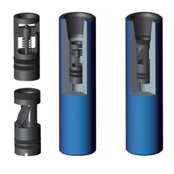
The WellStar® tubing-retrievable safety valve is a general production, hydraulically operated, downhole TRSV. The rugged hydraulic actuator of the WellStar safety valve provides durability and isolates the internal workings from well fluids through its unique construction. The metal-to-metal (MTM) sealing integrity in the body joints and closure mechanism places it in a premium valve category while featuring an economical price. Proven through years of installations, the simple, compact design enhances the valve’s overall reliability and provides for trouble-free operation.

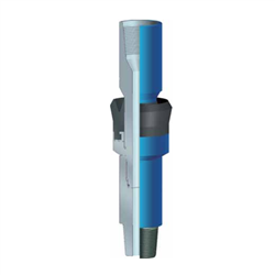
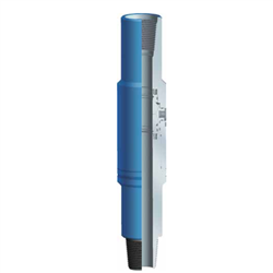
The TSS series subsurface safety valves are tubing retrievable surface controlled subsurface safety valves. Compared with the TS series, the safety valve features super slim outer diameter design. The control line connects the valve to the surface, and the pressurization from surface on the control line controls the opening and closing of the flapper. This series of products includes self-equalizing and non-equalizing types.
This invention relates in general, to the operation of a subsurface safety valve installed in the tubing of a subterranean wellbore and, in particular, to an apparatus and method for locking out a subsurface safety valve and communicating hydraulic fluid through the subsurface safety valve.
One or more subsurface safety valves are commonly installed as part of the tubing string within oil and gas wells to protect against unwanted communication of high pressure and high temperature formation fluids to the surface. These subsurface safety valves are designed to shut in production from the formation in response to a variety of abnormal and potentially dangerous conditions.
As these subsurface safety valves are built into the tubing string, these valves are typically referred to as tubing retrievable safety valves ("TRSV"). TRSVs are normally operated by hydraulic fluid pressure which is typically controlled at the surface and transmitted to the TRSV via a hydraulic fluid line. Hydraulic fluid pressure must be applied to the TRSV to place the TRSV in the open position. When hydraulic fluid pressure is lost, the TRSV will operate to the closed position to prevent formation fluids from traveling therethrough. As such, TRSVs are fail safe valves.
As TRSVs are typically incorporated into the tubing string, removal of the tubing string to replace or repair the malfunctioning TRSV is required. As such, the costs associated with replacing or repairing the malfunctioning TRSV is quite high. It has been found, however, that a wireline retrievable safety valve ("WRSV") may be inserted inside the original TRSV and operated to provide the same safety function as the original TRSV. These insert valves are designed to be lowered into place from the surface via wireline and locked inside the original TRSV. This approach can be a much more efficient and cost-effective alternative to pulling the tubing string to replace or repair the malfunctioning TRSV.
It has been found, however, that operating conventional TRSVs to the locked out position and establishing this communication path has several inherent drawbacks. To begin with, the inclusion of such built-in lock out sleeves in each TRSV increases the cost of the TRSV, particularly in light of the fact that the built-in lock out sleeves are not used in the vast majority of installations. In addition, since these built-in lock out sleeves are not operated for extended periods of time, in most cases years, they may become inoperable before their use is required. Also, it has been found, that the communication path of the pre-machined radial bore creates a potential leak path for formation fluids up through the hydraulic control system. As noted above, TRSVs are intended to operate under abnormal well conditions and serve a vital and potentially lifesaving function. Hence, if such an abnormal condition occurred when one TRSV has been locked out, even if other safety valves have closed the tubing string, high pressure formation fluids may travel to the surface through the hydraulic line.
The present invention disclosed herein comprises an apparatus and method for establishing a communication path for hydraulic fluid to a wireline retrievable safety valve from a rod piston operated tubing retrievable safety valve. The apparatus and method of the present invention do not require a built-in lock out sleeve in the rod piston operated tubing retrievable safety valve. Likewise, the apparatus and method of the present invention avoid the potential for formation fluids to travel up through the hydraulic control line associated with a pre-drilled radial bore in the tubing retrievable safety valve.
In broad terms, the apparatus of the present invention allows hydraulic control to be communicated from a non annular hydraulic chamber of a rod piston operated tubing retrievalbe safety valve to the interior thereof so that the hydraulic fluid may, for example, be used to operate a wireline retrievable safety valve is detected and a need exists to otherwise achieve the functionality of the rod piston operated tubing retrievable safety valve.
The rod piston operated tubing retrievable safety valve of the present invention has a housing having a longitudinal bore extending therethrough. The safety valve also has a non annular hydraulic chamber in a sidewall portion thereof. A valve closure member is mounted in the housing to control fluid flow through the longitudinal bore by operating between closed and opened positions. A flow tube is disposed within the housing and is used to shift the valve closure member between the closed and opened positions. A rod piston, which is slidably disposed in the non annular hydraulic chamber of the housing, is operably coupled to the flow tube. The safety valve of the present invention also has a pocket in the longitudinal bore.
In one embodiment of the present invention a communication tool is used to establish a communication path between the non annular hydraulic chamber in a sidewall portion of the safety valve and the interior of the safety valve. In this embodiment, the communication tool has a first section and a second section that are initially coupled together using a shear pin or other suitable coupling device. A set of axial locating keys is operably attached to the first section of the tool and is engagably positionable within a profile of the safety valve. The tool includes a radial cutting device that is radially extendable through a window of the second section. For example, the radial cutting device may include a carrier having an insert removably attached thereto and a punch rod slidably operable relative to the carrier to radially outwardly extend the insert exteriorly of the second section.
The tool also includes a circumferential locating key that is operably attached to the second section of the tool. The circumferential locating key is engagably positionable within the pocket of the safety valve. Specifically, when the first and second sections of the tool are decoupled, the second section rotations relative to the first section until the circumferential locating key engages the pocket, thereby circumferentially aligning the radial cutting device with the non annular hydraulic chamber. A torsional biasing device such as a spiral wound torsion spring places a torsional load between the first and second sections such that when the first and second sections are decoupled, the second section rotates relative to the first section. A collet spring may be used to radially outwardly bias the circumferential locating key such that the circumferential locating key will engage the pocket, thereby stopping the rotation of the second section relative to the first section. Once the circumferential locating key has engaged the pocket, the radial cutting device will be axially and circumferentially aligned with the non annular hydraulic chamber. Through operation of the radial cutting device, a communication path is created from the non annular hydraulic fluid chamber to the interior of the safety valve.
As such, hydraulic fluid may now be communicated down the existing hydraulic lines to the interior of the tubing. Once this communication path exists, for example, a wireline retrievable safety valve may be positioned within the rod piston operated tubing retrievable safety valve such that the hydraulic fluid pressure from the hydraulic system may be communicated to a wireline retrievable safety valve.
In another embodiment of the present invention, a lock out and communication tool is used to lock out the safety valve and then establish a communication path between the non annular hydraulic chamber in a sidewall portion of the safety valve and the interior of the safety valve. In this embodiment, the lock out and communication tool is lowered into the safety valve until the lock out and communication tool engages the flow tube. The lock out and communication tool may then downwardly shift the flow tube, either alone or in conjunction with an increase in the hydraulic pressure acting on the rod piston, to operate the valve closure member from the closed position to the fully open position. Alternatively, if the safety valve is already in the open position, the lock out and communication tool simply prevents movement of the flow tube to maintain the safety valve in the open position. Thereafter, the lock out and communication tool interacts with the safety valve as described above with reference to the communication tool to communicate hydraulic fluid from the non annular hydraulic fluid chamber to the interior of the safety valve.
One method of the present invention that utilizes the communication tool involves inserting the communication tool into the safety valve, locking the communication tool within the safety valve with the safety valve in a valve open position, axially aligning the radially cutting device with the non annular hydraulic chamber, circumferentially aligning the radially cutting device with the non annular hydraulic chamber and penetrating the radially cutting device through the sidewall portion and into the non annular hydraulic chamber to create a communication path between the non annular hydraulic chamber and the interior of the safety valve.
In addition, a method of the present invention that utilizes the lock out and communication tool involves engaging the flow tube of the safety valve with the lock out and communication tool, retrieving the lock out and communication tool from the safety valve and maintaining the safety valve in the valve open position by preventing movement of the rod piston with an insert that is left in place within the sidewall portion when the remainder of the radial cutting tool is retracted.
Described hereinafter is a method for communicating hydraulic fluid through a tubing retrievable safety valve having a non annular chamber in a sidewall portion thereof, the method comprising the steps of: locating a communication tool within the tubing retrievable safety valve; and
creating a fluid passageway between the non annular hydraulic chamber and the interior of the tubing retrievable safety valve with the communication tool.
Ideally the step of creating a fluid passageway between the non annular hydraulic chamber and the interior of the tubing retrievable safety valve with the communication tool comprises penetrating through the sidewall portion and into the non annular hydraulic chamber. The step of locating the communication tool within the tubing retrievable safety valve may further comprise engaging locating keys of the communication tool into a profile.
The method may also comprise the step of circumferentially aligning a locating key of the communication tool with a pocket of the tubing retrievable safety valve to prevent relative rotation therebetween. Preferably, this step of circumferentially aligning a locating key of the communication tool with a pocket of the tubing retrievable safety valve further comprises radially outwardly shifting the locating key with a collet spring attached to the communication tool.
Ideally, the communication tool includes a cutting device which creates the fluid passageway between the non annular hydraulic chamber and the interior of the tubing retrievable safety valve.
The method may also comprise the step of actuating an anti-rotation mechanism to prevent rotation of at least a portion of the communication tool relative to the tubing retrievable safety valve. Ideally, actuating the anti-rotation mechanism includes shearing a shear pin coupling a portion of the cutting device to a portion of the communication tool. Also, actuating the anti-rotation mechanism may include aligning a protruding portion of the communication tool with a recessed portion of the tubing retrievable safety valve. Furthermore, actuating the anti-rotation mechanism may further include shifting the protruding portion of the communication tool radially outward to engage the recessed portion of the tubing retrievable safety valve. Also, actuating the anti-rotation mechanism may include circumferentially aligning the cutting device with the non annular hydraulic chamber.
Ideally, the step of creating the fluid passageway includes mechanically cutting the sidewall portion of the tubing retrievable safety valve. Also, the mechanically cutting step may be carried out with a mechanical cutting device preferably in the form of a punch. The cutting device may be a radial cutting device which creates a fluid passageway from the non annular hydraulic chamber to the interior of the tubing retrievable safety valve by radially penetrating through the sidewall portion and into the non annular hydraulic chamber.
Furthermore, the step of creating a fluid passageway from the non annular hydraulic chamber to the interior of the tubing retrievable safety valve by radially penetrating the radial cutting device through the sidewall portion and into the non annular hydraulic chamber may further comprise radially outwardly shifting the radially cutting device with a punch rod. Also, the step of creating a fluid passageway from the non annular hydraulic chamber to the interior of the tubing retrievable safety valve by radially penetrating the radial cutting device through the sidewall portion into the non annular hydraulic chamber may further comprise disposing an insert having a fluid passageway in the sidewall portion of the tubing retrievable safety valve.
Also described below is a system for communicating hydraulic fluid to a wireline retrievable safety valve comprising: a tubing retrievable safety valve having a non annular hydraulic chamber in a sidewall portion thereof; and
a communication tool selectively locatable within the tubing retrievable safety valve, the communication tool creating a fluid passageway between the non annular hydraulic chamber and the interior of the tubing retrievable safety valve by penetrating through the sidewall portion and into the non annular hydraulic chamber such that when the wireline retrievable safety valve is positioned within the tubing retrievable safety valve, hydraulic fluid is communicatable thereto through the fluid passageway.
Ideally, the tubing retrievable safety valve further comprises a pocket that engageably receives a locating key of the communication tool whereby the interaction between the locating key and the pocket prevents relative rotation between the communication tool and the tubing retrievable safety valve.
Also described hereinafter is a safety valve for downhole use in a well comprising: a housing having a longitudinal bore extending therethrough and having a non annular hydraulic chamber in a sidewall portion thereof, the longitudinal bore operable to receive a communication tool therein that creates a fluid passageway between the non annular hydraulic chamber and the interior of the tubing retrievable safety valve by penetrating through the sidewall portion and into the non annular hydraulic chamber;
a valve closure member mounted in the housing to control fluid flow through the longitudinal bore, the valve closure member having closed and open positions;
The longitudinal bore may be operable to receive a communication tool therein such that relative rotation between at least a portion of the communication tool and the safety valve is substantially prevented. The valve may also further comprise an anti rotation mechanism associated with the longitudinal bore. The valve may also further comprise a pocket in the longitudinal bore for engaging a locating key of the communication tool whereby the interaction between the locating key and the pocket substantially prevents relative rotation between the at least a portion of the communication tool and the safety valve.
The sidewall portion may have a radially reduced region. The valve may further comprise a profile in the longitudinal bore for engaging a set of axial locating keys of the communication tool. The valve ideally comprises a spring positioned between the housing and the flow tube that biases the valve closure member toward the closed position. The valve may also further comprise a hydraulic fluid operating against the rod piston in the non annular hydraulic chamber that biases the valve closure member toward the open piston.
For a more complete understanding of the present invention understanding of the present invention, including its features and advantages, reference is now made to the detailed description of the invention, taken in conjunction with the accompanying drawings in which like numerals identify like parts and in which: Figure 1 is a schematic illustration of an offshore production platform wherein a wireline retrievable safety valve is being lowered into a tubing retrievable safety valve to take over the functionality thereof;
Figures 2A-2B are cross sectional views of successive axial sections of a rod piston operated tubing retrievable safety valve of the present invention in its valve closed position;
Figures 3A-3B are cross sectional views of successive axial sections of a rod piston operated tubing retrievable safety valve of the present invention in its valve open position;
Figures 5A-5B are cross sectional views of successive axial sections of a communication tool of the present invention in its running position and disposed in a rod piston operated tubing retrievable safety valve of the present invention;
Figures 6A-6B are cross sectional views of successive axial sections of a communication tool of the present invention in its locked position and disposed in a rod piston operated tubing retrievable safety valve of the present invention;
Figures 7A-7B are cross sectional views of successive axial sections of a communication tool of the present invention in its orienting position and disposed in a rod piston operated tubing retrievable safety valve of the present invention;
Figures 8A-8B are cross sectional views of successive axial sections of a communication tool of the present invention in its perforating position and disposed in a rod piston operated tubing retrievable safety valve of the present invention;
Figures 9A-9B are cross sectional views of successive axial sections of a communication tool of the present invention in its retrieving position and still substantially disposed in a rod piston operated tubing retrievable safety valve of the present invention; and
Figures 10A-10C are cross sectional views of successive axial sections of a lock out and communication tool of the present invention disposed in a rod piston operated tubing retrievable safety valve of the present invention.
Referring to figure 1, an offshore oil and gas production platform having a wireline retrievable safety valve lowered into a tubing retrievable safety valve is schematically illustrated and generally designated 10. A semi-submersible platform 12 is centered over a submerged oil and gas formation 14 located below sea floor 16. Wellhead 18 is located on deck 20 of platform 12. Well 22 extends through the sea 24 and penetrates the various earth strata including formation 14 to form wellbore 26. Disposed within wellbore 26 is casing 28. Disposed within casing 28 and extending from wellhead 18 is production tubing 30. A pair of seal assemblies 32, 34 provide a seal between tubing 30 and casing 28 to prevent the flow of production fluids therebetween. During production, formation fluids enter wellbore 26 through perforations 36 in casing 28 and travel into tubing 30 to wellhead 18.
Coupled within tubing 30 is a tubing retrievable safety valve 38. As is well known in the art, multiple tubing retrievable safety valves are commonly installed as part of tubing string 30 to shut in production from formation 14 in response to a variety of abnormal and potentially dangerous conditions. For convenience of illustration, however, only tubing retrievable safety valve 38 is shown.
Tubing retrievable safety valve 38 is operated by hydraulic fluid pressure communicated thereto from surface installation 40 and hydraulic fluid control conduit 42. Hydraulic fluid pressure must be applied to tubing retrievable safety valve 38 to place tubing retrievable safety valve 38 in the open position. When hydraulic fluid pressure is lost, tubing retrievable safety valve 38 will operate to the closed position to prevent formation fluids from traveling therethrough.
If, for example, tubing retrievable safety valve 38 is unable to properly seal in the closed position or does not properly open after being in the closed position, tubing retrievable safety valve 38 must typically be repaired or replaced. In the present invention, however, the functionality of tubing retrievable safety valve 38 may be replaced by wireline retrievable safety valve 44, which may be installed within tubing retrievable safety valve 38 via wireline assembly 46 including wireline 48. Once in place within tubing retrievable safety valve 38, wireline retrievable safety valve 44 will be operated by hydraulic fluid pressure communicated thereto from surface installation 40 and hydraulic fluid line 42 through tubing retrievable safety valve 38. As with the original configuration of tubing retrievable safety valve 38, the hydraulic fluid pressure must be applied to wireline retrievable safety valve 44 to place wireline retrievable safety valve 44 in the open position. If hydraulic fluid pressure is lost, wireline retrievable safety valve 44 will operate to the closed position to prevent formation fluids from traveling therethrough.
Referring now to figures 2A and 2B, therein is depicted cross sectional views of successive axial sections a tubing retrievable safety valve embodying principles of the present invention that is representatively illustrated and generally designated 50. Safety valve 50 may be connected directly in series with production tubing 30 of figure 1. Safety valve 50 has a substantially cylindrical outer housing 52 that includes top connector subassembly 54, intermediate housing subassembly 56 and bottom connector subassembly 58 which are threadedly and sealing coupled together.
It should be apparent to those skilled in the art that the use of directional terms such as top, bottom, above, below, upper, lower, upward, downward, etc. are used in relation to the illustrative embodiments as they are depicted in the figures, the upward direction being toward the top of the corresponding figure and the downward direction being toward the bottom of the corresponding figure. As such, it is to be understood that the downhole components described herein may be operated in vertical, horizontal, inverted or inclined orientations without deviating from the principles of the present invention.
Hydraulic control pressure is communicated to longitudinal bore 60 of safety valve 50 via control conduit 42 of figure 1. A rod piston 68 is received in slidable, sealed engagement against longitudinal bore 60. Rod piston 68 is connected to a flow tube adapter 70 which is threadedly connected to a flow tube 72. Flow tube 72 has profile 74 and a downwardly facing annular shoulder 76.
A flapper plate 78 is pivotally mounted onto a hinge subassembly 80 which is disposed within intermediate housing subassembly 56. A valve seat 82 is defined within hinge subassembly 80. It should be understood by those skilled in the art that while the illustrated embodiment depicts flapper plate 78 as the valve closure mechanism of safety valve 50, other types of safety valves including those having different types of valve closure mechanisms may be used without departing from the principles of the present invention, such valve closure mechanisms including, but not limited to, rotating balls, reciprocating poppets and the like.
In normal operation, flapper plate 78 pivots about pivot pin 84 and is biased to the valve closed position by a spring (not pictured). When safety valve 50 must be operated from the valve closed position, depicted in figures 2A-2B, to the valve opened position, depicted in figures 3A-3B, hydraulic fluid enters longitudinal bore 60 and acts on rod piston 68. As the downward hydraulic force against rod piston 68 exceeds the upward bias force of spiral wound compression spring 86, flow tube 72 moves downwardly with rod piston 68. As flow tube 72 continues to move downwardly, flow tube 72 contacts flapper closure plate 78 and forces flapper closure plate 78 to the open position.
When safety valve 50 must be operated from the valve open position to the valve closed position, hydraulic pressure is released from conduit 42 such that spring 86 acts on shoulder 76 and upwardly bias flow tube 72. As flow tube 72 is retracted, flapper closure plate 78 will rotate about pin 84 and seal on seat 82.
If safety valve 50 becomes unable to properly seal in the closed position or does not properly open after being in the closed position, it is desirable to reestablish the functionality of safety valve 50 without removal of tubing 30. In the present invention this is achieved by inserting a lock out and communication tool into the central bore of safety valve 50.
The operation of communication tool 100 of the present invention will now be described relative to safety valve 50 of the present invention with reference to figures 5A-5B, 6A-6B, 7A-7B, 8A-8B and 9A-9B. In figures 5A-5B, communication tool 100 is in its running configuration. Communication tool 100 is positioned within the longitudinal central bore of safety valve 50. As communication tool 100 is lowered into safety valve 50, downwardly facing annular shoulder 154 of main mandrel 132 contacts profile 74 of flow tube 72. Main mandrel 132 may downwardly shift flow tube 72, either alone or in conjunction with an increase in the hydraulic pressure within longitudinal chamber 60, operating flapper closure plate 78 from the closed position, see figures 2A-2B, to the fully open position, see figures 3A-3B. Alternatively, if safety valve 50 is already in the open position, main mandrel 132 simply holds flow tube 72 in the downward position to maintain safety valve 50 in the open position. Communication tool 100 moves downwardly relative to outer housing 52 of safety valve 50 until axial locating keys 112 of communication tool 100 engage profile 62 of safety valve 50.
Once axial locating keys 112 of communication tool 100 engage profile 62 of safety valve 50, downward jarring on communication tool 100 shifts fish neck 124 along with fish neck mandrel 126, fish neck mandrel extension 128, upper mandrel 116 and expander mandrel 118 downwardly relative to safety mandrel 50 and punch rod 130. This downward movement shifts expander mandrel 118 behind axial locating keys 112 which locks axial locating keys 112 into profile 62, as best seen in figures 6A-6B.
In this locked configuration of communication tool 100, dogs 122 are aligned with radially reduced interior section 106 of upper housing subassembly 104. As such, additional downward jarring on communication tool 100 outwardly shifts dogs 122 which allows fish neck mandrel extension 128 to move downwardly. This allows the lower surface of fish neck 124 to contact the upper surface of punch rod 130. Continued downward jarring with a sufficient and predetermined force shears pins 136, as best seen in figures 7A-7B. When pins 136 shear, this allows punch rod 130 and main mandrel 132 to move axially downwardly relative to housing 102 and expander mandrel 118 of communication tool 100 and safety valve 50. This downward movement axially aligns carrier 146 and insert 148 with radially reduced area 64 and axially aligns circumferential locating key 140 with pocket 66 of safety valve 50.
In addition, when pins 136 shear, this allows punch rod 130 and main mandrel 132 to rotate relative to housing 102 and expander mandrel 118 of communication tool 100 and safety valve 50 due to the torsional force stored in torsion spring 138. This rotational movement circumferentially aligns carrier 146 and insert 148 with longitudinal bore 60 of safety valve 50. This is achieved due to the interaction of circumferential locating key 140 and pocket 66. Specifically, as punch rod 130 and main mandrel 132 rotate relative to safety valve 50, collet spring 142 radially outwardly biases circumferential locating key 140. Thus, when circumferential locating key 140 becomes circumferentially aligned with pocket 66, circumferential locating key 140 moves radially outwardly into pocket 66 stopping the rotation of punch rod 130 and main mandrel 132 relative to safety valve 50. By axially and circumferentially aligning circumferential locating key 140 with pocket 66, carrier 146 and insert 148 become axially and circumferentially aligned with longitudinal bore 60 of safety valve 50.
Once carrier 146 and insert 148 are axially and circumferentially aligned with longitudinal bore 60 of safety valve 50, communication tool 100 is in its perforating position, as depicted in figures 8A-8B. In this configuration, additional downward jarring on communication tool 100, of a sufficient and predetermined force, shears pin 134 which allow punch rod 130 to move downwardly relative to main mandrel 132. As punch rod 130 move downwardly, insert 148 penetrates radially reduced region 64 of safety valve 50. The depth of entry of insert 148 into radially reduced region 64 is determined by the number of jars applied to punch rod 130. The number of jars applied to punch rod 130 is predetermined based upon factors such as the thickness of radially reduced region 64 and the type of material selected for outer housing 52.
With the use of communication tool 100 of the present invention, fluid passageway 150 of insert 148 provides a communication path for hydraulic fluid from longitudinal bore 60 to the interior of safety valve 50. Once insert 148 is fixed within radially reduced region 64, communication tool 100 may be retrieved to the surface, as depicted in figures 9A-9B. In this configuration, punch rod 130 has retracted from behind carrier 146, fish neck mandrel extension 128 has retracted from behind keys 106 and expander mandrel 118 has retracted from behind axial locating keys 112 which allows communication tool 100 to release from safety valve 50. Insert 148 now prevents the upward movement of rod piston 68 and flow tube 72 which in turn prevents closure of flapper closure plate 78, thereby locking but safety valve 50. In addition, flow passageway 150 of insert 148 allow for the communication of hydraulic fluid from longitudinal bore 60 to the interior of safety valve 50 which can be used, for example, to operate a wireline retrievable subsurface safety valve that is inserted into locked out safety valve 50.
In operation, as lock out and communication tool 200 is positioned within the longitudinal central bore of safety valve 50 as described above with reference to tool 100, flapper closure plate 78 is operated from the closed position, see figures 2A-2B, to the fully open position, see figures 3A-3B. Lock out and communication tool 200 moves downwardly relative to outer housing 52 of safety valve 50 until axial locating keys 212 of lock out and communication tool 200 engage profile 62 of safety valve 50 and are locked therein.
In this locked configuration of lock out and communication tool 200, shears pins 236 may be sheared in response to downward jarring which allows punch rod 230 and main mandrel 232 to move axially downwardly relative to housing 202 and expander mandrel 218 of lock out and communication tool 200 and safety valve 50. As explained above, this downward movement axially aligns carrier 246 and insert 248 with radially reduced area 64. In addition, circumferential locating key 240 is both axially and circumferentially aligned with pocket 66 of safety valve 50.
By axially and circumferentially aligning circumferential locating key 240 with pocket 66, carrier 246 and insert 248 become axially and circumferentially aligned with longitudinal bore 60 of safety valve 50 such that additional downward jarring on lock out and communication tool 200 of a sufficient and predetermined force shears pin 234 which allow punch rod 230 to move downwardly relative to main mandrel 232 and main mandrel extension 260. As punch rod 230 move downwardly, insert 248 penetrates radially reduced region 64 of safety valve 50. Further travel of punch rod 230 downwardly relative to main mandrel 232 and main mandrel extension 260 causes dimpling member 268 to contact and form a dimple in the inner wall of safety valve 50 which prevents upward travel of piston 68 after lock out and communication tool 200 is retrieved from safety valve 50.
The unique interaction of lock out and communication tool 200 of the present invention with safety valve 50 of the present invention thus allow for the locking out of a rod piston operated safety valve and for the communication of its hydraulic fluid to operate, for example, an insert valve.
Our downhole safety valves provide your testing operations with fail-safe sustained control downhole in the event of an emergency or to facilitate test procedures.

[1] 张梦婷,张勇. 国外井下安全阀的技术现状[J]. 石油机械,2008,36(7):81-84. doi:10.16082/j.cnki.issn.10014578.2008.07.019 ZHANG Mengting, ZHANG Yong. Technical status of subsurface safety valves at abroad[J]. Journal of Petroleum Machinery, 2008, 36(7):81-84. doi:10.16082/j.cnki.issn.1001-4578.2008.07.019
[2] 周大伟,钟功祥,梁政. 国内外井下安全阀的技术现状及发展趋势[J]. 石油矿场机械, 2007, 36(3):14-16. doi:10.3969/j.issn.1001-3482.2007.03.005 ZHOU Dawei, ZHONG Gongxiang, LIANG Zheng. Study of technical state and development tendency for downhole safety valve of domestic and foreign[J]. Oil Field Equipment, 2007, 36(3):14-16. doi:10.3969/j.issn.10013482.2007.03.005
[5] Al-YATEEM K S, HANBZAZAH S M, ALSYED S M, et al. First successful rigless conversion of subsurface safety valves from tubing retrievable to wireline retrievable in Middle East[C]. SPE 159202-MS 2012. doi:10.2118/159202-MS
[6] SCHLUMBERGER. Tubing-retrievable safety & injec tion valves[EB/OL].[2016-06-15]. http://www.slb.com/services/completions/safety_valves/tubing_retrievable_valves.aspx.
[7] HALIBURTON. Subsurface safety equipment[EB/OL].[2016-06-30]. http://www.halliburton.com/public/cps/contents/Books_and_Catalogs/web/CPSCatalog/09_Subsurface_Safety_Equip. pdf.
[8] BAKER Hughes. Subsurface safety systems[EB/OL].[2016-07-08]. https://www.bakerhughes.com/products-and-services/completions/well-completions/subsurfacesafety-systems.
[9] WEATHERFORD. Optimax series safety valves[EB/OL].[2016-07-15]. http://www.weatherford.com/en/productsservices/completion-and-stimulation/upper-completions/safety-systems.
[13] TAYLOR D M. Packer & safety valve development for ultra high pressure high temperature test & production wells[C]. OTC 23627-MS, 2012. doi:10.4043/23627-MS
[14] IMBO P, GANDINI G. Electro magnetic wireline retrievable-surface controlled subsurface safety valve:A new backup for surface controlled subsurface safety valve to avoid workover[C]. Ravenna, Italy, Offshore Mediterranean Conference and Exhibition, 2011.
[15] RAUSAND M, VATN J. Reliability modeling of surface controlled subsurface safety valves[J]. Reliability Engineering & System Safety, 1998, 61(1-2):159-166. doi:10.1016/S0951-8320(97)00066-5
[17] THAI D, ORZECHOWSKI D, PINARD G. Case study:Deepwater design verification and validation testing for subsurface safety valves for HPHT environments[C]. OTC 28983-MS, 2018. doi:10.4043/28983-MS
[18] LEBOEUF G J, ADAMS S M, PITTMAN A, et al. New design in surface-controlled subsurface safety valves resolves valve problems in subsea completions in the Gulf of Mexico[C]. OTC 19620-MS, 2008. doi:10.4043/19620MS
[19] AL-YATEEM K S, HANBZAZAH S M, ALSYED S M, et al. First successful rigless conversion of subsurface safety valves from tubing retrievable to wireline retrievable in Middle East[C]. SPE 159202-MS, 2012. doi:10.2118/159202-MS
[20] CHARPENTIER T V J, BARAKA-LOKMANE S, NEVILLE A, et al. Comparison of characteristic of antiscaling coating for subsurface safety valve for use in oil and gas industry[C]. IPTC 17953-MS, 2014. doi:10.2523/IPTC-17953-MS
[21] KUMAR D, WELCH J C, XU Z. Reduction in scale buildup from sub-surface safety valve using hydrophobic material coating[C]. SPE 166218-MS, 2013. doi:10.2118/166218-MS
[22] EHTESHAM M A, TUCKER R, GILES J. Downhole safety valve for well-intervention operations:Design, testing, and successful case history[C]. SPE 142887-MS, 2011. doi:10.2118/142887-MS
[23] WAGNER A N. Capillary based surface controlled subsurface safety valve systems solution for problematic wells[C]. SPE 183837-MS, 2017. doi:10.2118/183837MS
[24] 周大伟. 井下安全阀系统设计与分析[D]. 成都:西南石油大学, 2007. ZHOU Dawei. Design and analysis of subsurface safety valves" system[D]. Chengdu:Southwest Petroleum University, 2007.
[25] 牛贵锋, 杨万有. 高温高压井下安全阀阀板优化研究[J]. 石油矿场机械, 2017, 46(2):11-16. doi:10.3969/j.issn.1001-3482.2017.02.003 NIU Guifeng, YANG Wanyou. Optimization of valve plate of high temperature and high pressure downhole safety valve[J]. Oil Field Equipment, 2017, 46(2):11-16. doi:10.3969/j.issn.1001-3482.2017.02.003
[27] 黎伟,宋伟,李乃禾,等. 滑套式井下安全阀设计及动态特性分析[J]. 中国安全生产科学技术, 2017, 13(2):159-163. doi:10.11731/j.issn.1673-193x.2017.02.028 LI Wei, SONG Wei, LI Naihe, et al. Design and dynamic characteristic analysis of sliding-sleeve subsurface safety valve[J]. Journal of Safety Science and Technology, 2017, 13(2):159-163. doi:10.11731/j.issn.1673193x.2017.02.028
[28] 李美求,阳康,周思柱,等. 自平衡井下安全阀动态平衡响应分析[J]. 液压与气动, 2017(6):70-74. doi:10.11832/j.issn.1000-4858.2017.06.014 LI Meiqiu, YANG Kang, ZHOU Sizhu, et al. Dynamic equilibrium response analysis for self-balancing subsurface safety valve[J]. Chinese Hydraulics & Pneumatics, 2017(6):70-74. doi:10.11832/j.issn.10004858.2017.06.014
[29] 李常友,孙宝全,董社霞,等. SC35-129A型井下安全阀的研制[J]. 石油机械, 2005, 33(1):43-44. doi:10.16082/j.cnki.issn.1001-4578.2005.01.014 LI Changyou, SUN Baoquan, DONG Shexia, et al. Development of model SC35-120A downhole safety valve[J]. Journal of Petroleum Machinery, 2005, 33(1):43-44. doi:10.16082/j.cnki.issn.1001-4578.2005.01.014
[31] 孔学云, 李宝龙, 齐海涛, 等. 88.9 mm油管携带式井下安全阀研制[J]. 石油矿场机械, 2016, 45(9):49-52. doi:10.3969/j.issn.1001-3482.2016.09.011 KONG Xueyun, LI Baolong, QI Haitao, et al. Research and development of 3-12 in. tubing-retrievable subsurface safety valve[J]. Oil Field Equipment, 2016, 45(9):49-52. doi:10.3969/j.issn.1001-3482.2016.09.011
[32] 吴迪. 井下安全阀液体综合试验系统的研究[D]. 长春:长春理工大学, 2011. WU Di. Research on subsurface safety valve liquid test system[D]. Changchun:Changchun University of Science and Technology, 2011.
[33] 王战友. 井下安全阀气体综合试验检测系统研究[D]. 长春:长春理工大学, 2014. WANG Zhanyou. Research on subsurface safety valve gas test system[D]. Changchun:Changchun University of Science and Technology, 2014.
[34] SHANG Chenmin, ZHANG Dongmei, ZHANG Xinming. Subsurface safety valve automation test systems design[J]. Applied Mechanics & Materials, 2014, 543-547:1188-1191. doi:10.4028/www.scientific.net/AMM.543547.1188
[36] 张福涛. 海上油井井下安全阀检测系统设计[J]. 内蒙古石油化工,2012(24):79-80. doi:10.3969/j.issn.10067981.2012.24.036 ZHANG Futao. Testing system design of offshore well subsurface safety valves[J]. Inner Mongolia Petrochemical Industry, 2012(24):79-80. doi:10.3969/j.issn.10067981.2012.24.036

Valtorc USA Fire Safe Ball Valves are generally supplied with manual hand lever or gear actuator operated, depending on valve size. We also offering Ball Valves with Pneumatic Single Acting Actuator, Pneumatic Double Acting Actuator, Rotary Actuator, Quarter Turn Actuator or Electrical actuator operated for automation.
Valtorc USA"s Process Valves & Automation Fire Safe Design Ball Valves are also available with different type of Seat, Seal & Packing material such as P.T.F.E. (Virgin) / Glass Filled P.T.F.E. / Carbon Filled P.T.F.E. / Graphite (Grafoil) to suit special requirement of client.


 8613371530291