
farris safety valve catalog free sample
Check ValvesCheck Valve – A check valve, clack valve, non-return valve or one-way valve is a valve that normally allows fluid (liquid or gas) to flow through it in only one direction. Gate Valve – A gate valve, also known as a sluice valve, is a valve which opens by lifting a round or rectangular gate/wedge out of the path of the fluid. The distinct feature of a gate valve is the sealing surfaces between the gate and seats are planar, so gate valves are often used when a straight-line flow of fluid and minimum restriction is desired Globe Valve – A Globe valve is a type of valve used for regulating flow in a pipeline, consisting of a movable disk-type element and a stationary ring seat in a generally spherical body. Globe valves are named for their spherical body shape with the two halves of the body being separated by an internal baffle. This has an opening that forms a seat onto which a movable plug can be screwed in to close (or shut) the valve. The plug is also called a disc or disk. In globe valves, the plug is connected to a stem which is operated by screw…
Our type numbering system simplifies the selection and specifying of Farris pressure relief valves because the digits that comprise a specific type number
have a distinct significance. The digits describe the basic valve series, orifice, seat and internal construction, inlet temperature range, body, bonnet and
4. For a valve in complete stainless steel, add “N4” to suffix. Example: 26HB10-120/N4. For optional complete Inconel bellows, add “N4/SP”. Example: 26HB10-120/N4/SP.
1. Standard seat tightness for “O” ring valves is no bubbles at 90% of set pressure for both conventional and bellows valves. At set pressures of 50 psig and below, leakage test shall
1. All valves supplied with plain caps unless otherwise specified. Standard suffix for type number is “-120”. For other cap construction, refer to page 69.
6. Optional equipment includes: air set device for set pressure testing, extra large lapping glass for valve seat maintenance, spring compression device for set
While this information is presented in good faith and believed to be accurate, Farris Engineering, division of Curtiss-Wright Flow Control Corporation, does not guarantee satisfactory
fitness or any other matter with respect to the products, nor as a recommendation to use any product or process in conflict with any patent. Farris Engineering, division of

The Farris Advantage................................................................................. 2 Cap and Lever Materials.......................................................................... 68
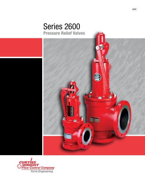
2600 Series Construction.......................................................................... 4 Remoter, Bugproof Vent and Valve Position Indicators.............................. 70
Definitions................................................................................................. 9 Valve Dimensions and Weights...........................................................72-75
Series 2600S Exposed Spring.................................................................. 15 Conventional Valves................................................................................. 84
2600/2600L Balanced Piston Design....................................................... 16 BalanSeal Valves..................................................................................... 85
1.The threaded connection between the valve nozzle and the valve inlet to avoid distortion on the nozzle seating surface.
relief valve to resist these discharge piping strains materially Long radius elbow
the forces resulting from the body and bonnet pressure when the valve is 2.Corrosive Service In Farris pressure relief valves on corrosive service,
into the valve body, or other techniques are used in an attempt to keep the guiding surfaces during valve operation. This reduces the corrosive
huddling chamber or body pressure away from the topside of the disc to effect of the lading fluid on the guiding surfaces and valve spring, so
1.High Temperature In Farris pressure relief valves on high temperature or vapor stream, there is no induced or forced flow in the Farris design
periods than in competitive designs. The Farris design avoids all these difficulties by discharging directly from
The Farris pressure relief valve design incorporates an integral sleeve polished to produce flatness (as measured with optical flats) that deviates
sleeve guide is extended above the top of the guide flange, minimizing the elimination of thermal distortion are integral design features of the valve.
Elimination of Thermal Distortion In a pressure relief valve, especially disc
All Stainless Steel Stem Construction The Farris two-piece design of disc holder and stem r etainer features
The Farris pressure relief valve design features an all stainless steel stem. a positive locking device called the disc holder lock screw. Any attempt
surface. This allows complete freedom of action for alignment purposes The Farris pressure relief valve is available as a conventional valve and
while retaining the positive connection of the threads. It also eliminates as a BalanSeal (balanced bellows) valve. The conversion of this valve
sufficiently positive during valve operations and may be inadvertently or removal of the balanced bellows and bellows gasket in the valve, and
left out during maintenance. the coincidental removal or replacement of a pipe plug in the valve bonnet
guide Although the Farris pressure relief valve does not induce circulation of the
5.Drilling of all flanges always straddles the valve center line. no additional temperature compensation. Where the set pressure is above
Valve Trim tested on air. When steam valves are tested on air, compensation shown
Series valves are located on pages 12 and 13. For low temperature and Low set pressure limits are indicated in the following table. These limits
For best performance in process applications, we recommend pressure Code, Section VIII. Accordingly, pressure relief valve requirements for
relief valves be set to open at a minimum of 10% or 25 psig above the such applications are governed by other codes and standards that should
relief valve. Refer to ASME Section VIII Pressure Vessel Code, Appendix M, The sizing equations for compressible fluids provided herein are valid for
Paragraph M-10, Pressure Differentials for Pressure Relief Valves. sonic flow conditions and should not be used to size pressure relief valves
Safety Valve – an automatic pressure relieving device actuated by the Overpressure – a pressure increase over the set pressure of a pressure
static pressure upstream of the valve, and characterized by rapid full relief valve, usually expressed as a percentage of the set pressure.
Relief Valve – an automatic pressure relieving device actuated by the working pressure of the vessel during discharge through the pressure
static pressure upstream of the valve, which opens in proportion to the relief valve, expressed as a percent of that pressure or in pounds per
suitable for use as either a safety or relief valve, depending on the application. pressure relief valve and actual reseating pressure, expressed as a
prevent the further flow of fluid after normal conditions have been restored. Lift – the actual travel of the disc away from closed position when a valve
at which the pressure relief valve is adjusted to open under service Back Pressure – the static pressure existing at the outlet of a pressure
under service conditions. In a relief or safety relief valve in liquid service, Superimposed Back Pressure – the static pressure existing at the outlet
flows from the valve perpendicular to the outlet. is the result of pressure in the discharge system from other sources when
back pressure. It is applicable only when a conventional type safety - Constant Superimposed Back Pressure – back pressure which does
relief valve is being used in service against a constant superimposed not change appreciably under any condition of operation whether the
the inlet static pressure at which the pressure relief valve is adjusted to the outlet of a pressure relief device, which does not remain constant
Our type numbering system simplifies the selection and specifying of Farris pressure relief valves because the digits that comprise a specific type number
have a distinct significance. The digits describe the basic valve series, orifice, seat and internal construction, inlet temperature range, body, bonnet and
4. Inlet and outlet flange class and facing Valves – If an exact replacement valve is required, then the valve type,
6. O-ring seat pressure seal material, if required and material being supplied. If a specific valve is obsolete, a recommen-
9. Allowable overpressure* materials. Specify valve type, size and serial number. If the serial number
10 spring buttons. Specify valve type, size, serial number, set pressure and
temperature service are listed on pages 18-21. Our selection of these corrosion resistant due to frequent valve operation and where parts
not all-inclusive, covers the most frequently used construction materials. internals and the complete valve are available in 316, Monel and Hastelloy
Note that Farris Engineering cannot guarantee valve service life, as offers S3 and S4 trim categories, depending on the degree of sub-zero
NACE International (formerly The National Association of Corrosion The customer must decide whether his application requires a valve in
Engineers) publishes two standards covering the use of equipment in compliance with NACE standards. Farris Engineering is responsible for
MR0103, Standard Material Requirements – Materials Resistant to Sulfide As part of the order requirement, Farris will verify that material hardness
for Use in H2S-Containing Environments in Oil and Gas Production. springs (for conventional and pilot operated valves only) in compliance
constructions. 2600 Series valves constructed of standard carbon steel To specify a valve with materials compliant to NACE specifications, add the
4. For a valve in complete stainless steel, add “N4” to suffix. Example: 26HB10-120/N4. For optional complete Inconel bellows, add “N4/SP”. Example: 26HB10-120/N4/SP.
secondary orifice (huddling chamber), causing the valve to pop fully open. Material Durometer Durometer
higher than normal, causing pressure relief valves to simmer but not fully -20 to 450 101 to 650 75 150 to 450 75
open. This can cause serious misalignment in the valve, and after the -20 to 125 75 75
pressure drops, the valve will very often continue to leak below the 125 to 450 90 90
Frequently operating pressures are too close to valve set pressures. As Ethylene 0 to 125 70 70
reducing the force that affects tightness. The Farris O-ring seat pressure 950 to 750 to
penetrated, causing leakage problems. The Farris O‑ring seat pressure -150 to 450 15 to 100 50 15 to 100 50
Farris O-ring seat pressure seal maintains tightness because the spring -150 to 450 80 80
valve is blowing. This creates leakage problems after the valve closes. 950 to 750 to
The Farris O-ring seat pressure seal absorbs the impact of these particles -20 to 550 90 90
seating surface on the nozzle as the valve closes. This reduces the Neoprene 751 to 751 to
be improved and maintained. • Main valve and pilot control soft good selection is based upon set pressure and
Nozzle icing results from the refrigerant effect of the flowing media when selection on valve set pressure and operating temperature.
a valve relieves. Ice actually forms on the seat, causing leakage. The Farris • Final soft goods selection should be chemically compatible with the process fluid.
Farris Engineering offers a complete line of large orifice, spring-loaded The 2600 Series large orifice valves are offered in both conventional and
safety relief valves for applications requiring flows larger than the standard BalanSeal construction with ASME Class 300 RF flanged inlet by ASME
API “T” orifice. These large orifice valves offer the same superior design, Class 150 RF flanged outlet, and temperature range from -20° to 800° F.
1. All valves supplied with plain caps unless otherwise specified. Standard suffix for type number is “-120”. For other cap construction, refer to page 69.
6. Optional equipment includes: air set device for set pressure testing, extra large lapping glass for valve seat maintenance, spring compression device for set
Note: The center to face dimension tolerances "B" and "C" are per API Standard 526: + 1/6" for valves up to and including 4" inlet size and + 1/8" over 4" inlet size.
Farris Nozzle Valves Depth of Groove +0.016, -0
VAPORS or GASES – Lbs./hr.: in a safe valve size. Isentropic coefficient n may be used instead
Viscosity Correction, Chart Sizing Method If BalanSeal valve construction is used and variable back pressure conditions
94/9/EC (European Pressure Relief Valve Engineering Software for Sizing and Selection
While this information is presented in good faith and believed to be accurate, Farris Engineering, division of Curtiss-Wright Flow Control Corporation, does not guarantee satisfactory
fitness or any other matter with respect to the products, nor as a recommendation to use any product or process in conflict with any patent. Farris Engineering, division of


 8613371530291