
farris safety valve series 2600 factory

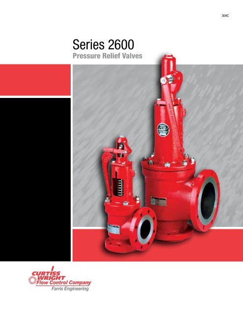
Farris’s pressure relief valves are designed to automatically protect your equipment against excessive overpressure. The Series 2600 pressure relief valves are designed to function equally well on air, gases, steam, or liquid service.
The pressure relief valve design incorporates several features which allow this valve to take a maximum amount of piping strain without hampering the functional characteristics of the valve or contributing to serious leakage.
The superior strength built into the body of the Farris pressure relief valve to resist these discharge piping strains materially reduces the deflection and distortion in the valve and reduces the leakage encountered, when at times, discharge piping strains become excessive.
The valve is engineered for exceptional tightness because of positive alignment, a high strength disc design, the elimination of thermal distortion and
It is a valve that is designed to detect and prevent changes in pressure which could lead to damage and failure in a number of applications. If the desired pressure is exceeded, the valve releases the excess pressure.

Our type numbering system simplifies the selection and specifying of Farris pressure relief valves because the digits that comprise a specific type number
have a distinct significance. The digits describe the basic valve series, orifice, seat and internal construction, inlet temperature range, body, bonnet and
4. For a valve in complete stainless steel, add “N4” to suffix. Example: 26HB10-120/N4. For optional complete Inconel bellows, add “N4/SP”. Example: 26HB10-120/N4/SP.
1. Standard seat tightness for “O” ring valves is no bubbles at 90% of set pressure for both conventional and bellows valves. At set pressures of 50 psig and below, leakage test shall
1. All valves supplied with plain caps unless otherwise specified. Standard suffix for type number is “-120”. For other cap construction, refer to page 69.
6. Optional equipment includes: air set device for set pressure testing, extra large lapping glass for valve seat maintenance, spring compression device for set
While this information is presented in good faith and believed to be accurate, Farris Engineering, division of Curtiss-Wright Flow Control Corporation, does not guarantee satisfactory
fitness or any other matter with respect to the products, nor as a recommendation to use any product or process in conflict with any patent. Farris Engineering, division of
Introduction This catalog covers Series 2600, 2600S and 2600L pressure relief valves including the latest infor ation available to assist m you in the sizing and selection of the proper valves for your application. Farris pressure relief valves have over a half century of proven performance providing auto atic and positive m protection against overpressure in thousands of industrial plants and facilities worldwide. Our earned reputation as “the First Line of Safety” is the result of countless Farris innovations combined with progressive engineering, sound design and high quality...
The Farris Advantage Farris pressure relief valves are designed to automatically protect your equipment against excessive overpressure. Every care is taken in the development, design and production of these valves to ensure complete dependability in performance. Our constant objective is to provide a superior valve that will assure ultimate protection at the lowest cost, both initially and throughout its service life. What is the Farris Advantage? Easy sizing and selection of valves using Farris catalogs and/or SizeMaster™ Sizing and Selection software. A method of specification and...
2600 Series Design Valve Selection This catalog simplifies the sizing and selection of Series 2600 process pressure relief valves. The pressure relief valves are presented here in an easy-to-understand format. Unless otherwise stated, references made to the Code refer specifically to ASME Section VIII, Division 1. Certified Capacity Code Compliance The Series 2600 pressure relief valves have been carefully constructed and tested in accordance with the requirements of the ASME Pressure Vessel Code, Section VIII. Their capacity rating for the applicable fluids is certified by the National...
2600 Series Construction Resistance to Discharge Piping Strains For most pressure relief valves, and particularly for those from which the discharge must be piped away to a remote location, it is almost impossible to keep piping strains away from the valve. The superior Farris pressure relief valve design incorporates several features which allow this valve to take a maximum amount of piping strain without hampering the functional characteristics of the valve or contributing to serious leakage. 1. The threaded connection between the valve nozzle and the valve inlet flange is located low in...
2600 Series Metallurgy Integral Sleeve Guide The Farris pressure relief valve design incorporates an integral sleeve guide (Fig 5), assuring continual positive alignment after the part has been manufactured, and including the same high corrosion resistant properties in the guide flange that are present in the sleeve portion of the guide. The sleeve guide is extended above the top of the guide flange, minimizing the possibility of corrosive or other foreign particles washing onto the guiding surfaces when the valve is relieving or when it is “breathing” as a result of atmospheric temperature...
2600 Series Operation All Stainless Steel Stem Construction The Farris pressure relief valve design features an all stainless steel stem. This construction cost-effectively eliminates dangerous sticking due to galvanic corrosion at the upper guiding point in the spring adjusting screw. The careful design of this upper bearing also ensures proper alignment and optimum freedom from galling and erratic popping. Positive Connection of Parts The Farris design incorporates a positive connection between the valve stem and the stem retainer as well as between the disc and disc holder (Fig 7). These...
2600 Series Operation Steam Jacketing for Better Heat Transfer In modern process plants, it is necessary to keep some valves and lines warm at all times to avoid solidification of the lading fluid and to guarantee the safety of equipment. Farris offers a steam jacket (Fig 8) to substantially increase the rate of heat transfer into the valve and, at the same time, simplify the problem of removing or dismantling the valve for maintenance. This design offers a separate two-piece jacket that installs on a standard valve body. See details on page 71. Simple, Accurate Adjustments The single Blow...
Definitions Safety Valve – an automatic pressure relieving device actuated by the static pressure upstream of the valve, and characterized by rapid full opening or pop action. Used for steam, gas or vapor service. Relief Valve – an automatic pressure relieving device actuated by the static pressure upstream of the valve, which opens in proportion to the increase in pressure over the opening pressure. Safety Relief Valve – an automatic pressure actuated relieving device suitable for use as either a safety or relief valve, depending on the application. Pressure Relief Valve – a pressure...
Type Numbering System Our type numbering system simplifies the selection and specifying of Farris pressure relief valves because the digits that comprise a specific type number have a distinct significance. The digits describe the basic valve series, orifice, seat and internal construction, inlet temperature range, body, bonnet and spring material, inlet flange class and Code liquid design. H Designates high pressure versions. Used for “Q”, “R”, “T”, & “U” orifices only. Series Number Orifice Areas Orifice Letter E BalanSeal with auxiliary balancing piston F BalanSeal with auxiliary...

Check ValvesCheck Valve – A check valve, clack valve, non-return valve or one-way valve is a valve that normally allows fluid (liquid or gas) to flow through it in only one direction. Gate Valve – A gate valve, also known as a sluice valve, is a valve which opens by lifting a round or rectangular gate/wedge out of the path of the fluid. The distinct feature of a gate valve is the sealing surfaces between the gate and seats are planar, so gate valves are often used when a straight-line flow of fluid and minimum restriction is desired Globe Valve – A Globe valve is a type of valve used for regulating flow in a pipeline, consisting of a movable disk-type element and a stationary ring seat in a generally spherical body. Globe valves are named for their spherical body shape with the two halves of the body being separated by an internal baffle. This has an opening that forms a seat onto which a movable plug can be screwed in to close (or shut) the valve. The plug is also called a disc or disk. In globe valves, the plug is connected to a stem which is operated by screw…
Farris is a renowned supplier in the design and production of a wide range of spring-loaded and pilot-operated pressure relief valves. They are used as safety devices to prevent over-pressurization of vessels, pipelines, and equipment. When a plant is equipped with Farris’ spring loaded and pilot operated PRV hardware, it’s protected by 70 years of manufacturing experience.
Farris pressure relief valves have earned a name in the industry for being trusted, top quality and long-lasting. When it comes to ensuring your machinery or equipment is protected from overpressure, Farris pressure relief valves are a great option.
The term pressure relief valves references both safety valves and expansion relief valves. The valve opens when it’s necessary to relieve pressure on a system.
While some basic components and activations in relieving pressure off a system may differ depending on the specific types of Farris relief valves, each main valve is intended to be 100% effective in keeping your equipment running safely and protect employees working nearby. Farris valve types range from flanged to spring loaded, threaded, pilot operated, and much more.

Since the early 1940s, the Farris Engineering unit of Curtiss-Wright Flow Control has designed and produced a wide range of spring-loaded and pilot-operated pressure relief valves. Used as safety devices, Farris pressure relief safety valves prevent over pressurization of vessels, pipelines, and equipment. Farris manufacturing is a company recognized as a leader in the hydrocarbon processing, refinery, petrochemical, natural gas production/transmission, pharmaceutical, and general processing industries worldwide. Their safety valves and other PRV hardware can be found across the globe – from the U.S. to the U.K. and S. America to China.
A pioneer in the field, the Farris Engineering company created many safety pressure relief products that remain industry standards. Integrating its core hardware technology with the information age, Farris developed computer software to assist customers in the sizing and selection of safety valves for all manner of piping and equipment. A recent reorganization of manufacturing plants and processes maximized production effectiveness to position the business unit at the forefront of the industry, with service and delivery second to none. If you are looking for an effective, high-quality safety valve and engineering expertise for any and all pressure relief management questions – look to the safety valve companies Farris Engineering and North American Machine Works.

The Farris Advantage................................................................................. 2 Cap and Lever Materials.......................................................................... 68
2600 Series Design................................................................................... 3 Test Gag Installations............................................................................... 69
2600 Series Construction.......................................................................... 4 Remoter, Bugproof Vent and Valve Position Indicators.............................. 70
2600 Series Metallurgy............................................................................. 5 Steam Jacketing Methods....................................................................... 71
Definitions................................................................................................. 9 Valve Dimensions and Weights...........................................................72-75
Series 2600L Certified Design................................................................. 14 Sizing Equations and Nomenclature......................................................... 84
Series 2600S Exposed Spring.................................................................. 15 Conventional Valves................................................................................. 84
2600/2600L Balanced Piston Design....................................................... 16 BalanSeal Valves..................................................................................... 85
1.The threaded connection between the valve nozzle and the valve inlet to avoid distortion on the nozzle seating surface.
relief valve to resist these discharge piping strains materially Long radius elbow
the forces resulting from the body and bonnet pressure when the valve is 2.Corrosive Service In Farris pressure relief valves on corrosive service,
into the valve body, or other techniques are used in an attempt to keep the guiding surfaces during valve operation. This reduces the corrosive
huddling chamber or body pressure away from the topside of the disc to effect of the lading fluid on the guiding surfaces and valve spring, so
1.High Temperature In Farris pressure relief valves on high temperature or vapor stream, there is no induced or forced flow in the Farris design
periods than in competitive designs. The Farris design avoids all these difficulties by discharging directly from
The Farris pressure relief valve design incorporates an integral sleeve polished to produce flatness (as measured with optical flats) that deviates
sleeve guide is extended above the top of the guide flange, minimizing the elimination of thermal distortion are integral design features of the valve.
Elimination of Thermal Distortion In a pressure relief valve, especially disc
All Stainless Steel Stem Construction The Farris two-piece design of disc holder and stem r etainer features
The Farris pressure relief valve design features an all stainless steel stem. a positive locking device called the disc holder lock screw. Any attempt
surface. This allows complete freedom of action for alignment purposes The Farris pressure relief valve is available as a conventional valve and
while retaining the positive connection of the threads. It also eliminates as a BalanSeal (balanced bellows) valve. The conversion of this valve
sufficiently positive during valve operations and may be inadvertently or removal of the balanced bellows and bellows gasket in the valve, and
left out during maintenance. the coincidental removal or replacement of a pipe plug in the valve bonnet
guide Although the Farris pressure relief valve does not induce circulation of the
5.Drilling of all flanges always straddles the valve center line. no additional temperature compensation. Where the set pressure is above
Valve Trim tested on air. When steam valves are tested on air, compensation shown
Series valves are located on pages 12 and 13. For low temperature and Low set pressure limits are indicated in the following table. These limits
For best performance in process applications, we recommend pressure Code, Section VIII. Accordingly, pressure relief valve requirements for
relief valves be set to open at a minimum of 10% or 25 psig above the such applications are governed by other codes and standards that should
relief valve. Refer to ASME Section VIII Pressure Vessel Code, Appendix M, The sizing equations for compressible fluids provided herein are valid for
Paragraph M-10, Pressure Differentials for Pressure Relief Valves. sonic flow conditions and should not be used to size pressure relief valves
Safety Valve – an automatic pressure relieving device actuated by the Overpressure – a pressure increase over the set pressure of a pressure
static pressure upstream of the valve, and characterized by rapid full relief valve, usually expressed as a percentage of the set pressure.
Relief Valve – an automatic pressure relieving device actuated by the working pressure of the vessel during discharge through the pressure
static pressure upstream of the valve, which opens in proportion to the relief valve, expressed as a percent of that pressure or in pounds per
suitable for use as either a safety or relief valve, depending on the application. pressure relief valve and actual reseating pressure, expressed as a
prevent the further flow of fluid after normal conditions have been restored. Lift – the actual travel of the disc away from closed position when a valve
at which the pressure relief valve is adjusted to open under service Back Pressure – the static pressure existing at the outlet of a pressure
under service conditions. In a relief or safety relief valve in liquid service, Superimposed Back Pressure – the static pressure existing at the outlet
flows from the valve perpendicular to the outlet. is the result of pressure in the discharge system from other sources when
back pressure. It is applicable only when a conventional type safety - Constant Superimposed Back Pressure – back pressure which does
relief valve is being used in service against a constant superimposed not change appreciably under any condition of operation whether the
the inlet static pressure at which the pressure relief valve is adjusted to the outlet of a pressure relief device, which does not remain constant
Our type numbering system simplifies the selection and specifying of Farris pressure relief valves because the digits that comprise a specific type number
have a distinct significance. The digits describe the basic valve series, orifice, seat and internal construction, inlet temperature range, body, bonnet and
4. Inlet and outlet flange class and facing Valves – If an exact replacement valve is required, then the valve type,
6. O-ring seat pressure seal material, if required and material being supplied. If a specific valve is obsolete, a recommen-
9. Allowable overpressure* materials. Specify valve type, size and serial number. If the serial number
10 spring buttons. Specify valve type, size, serial number, set pressure and
temperature service are listed on pages 18-21. Our selection of these corrosion resistant due to frequent valve operation and where parts
not all-inclusive, covers the most frequently used construction materials. internals and the complete valve are available in 316, Monel and Hastelloy
Note that Farris Engineering cannot guarantee valve service life, as offers S3 and S4 trim categories, depending on the degree of sub-zero
NACE International (formerly The National Association of Corrosion The customer must decide whether his application requires a valve in
Engineers) publishes two standards covering the use of equipment in compliance with NACE standards. Farris Engineering is responsible for
MR0103, Standard Material Requirements – Materials Resistant to Sulfide As part of the order requirement, Farris will verify that material hardness
for Use in H2S-Containing Environments in Oil and Gas Production. springs (for conventional and pilot operated valves only) in compliance
constructions. 2600 Series valves constructed of standard carbon steel To specify a valve with materials compliant to NACE specifications, add the
4. For a valve in complete stainless steel, add “N4” to suffix. Example: 26HB10-120/N4. For optional complete Inconel bellows, add “N4/SP”. Example: 26HB10-120/N4/SP.
secondary orifice (huddling chamber), causing the valve to pop fully open. Material Durometer Durometer
higher than normal, causing pressure relief valves to simmer but not fully -20 to 450 101 to 650 75 150 to 450 75
open. This can cause serious misalignment in the valve, and after the -20 to 125 75 75
pressure drops, the valve will very often continue to leak below the 125 to 450 90 90
Frequently operating pressures are too close to valve set pressures. As Ethylene 0 to 125 70 70
reducing the force that affects tightness. The Farris O-ring seat pressure 950 to 750 to
penetrated, causing leakage problems. The Farris O‑ring seat pressure -150 to 450 15 to 100 50 15 to 100 50
Farris O-ring seat pressure seal maintains tightness because the spring -150 to 450 80 80
valve is blowing. This creates leakage problems after the valve closes. 950 to 750 to
The Farris O-ring seat pressure seal absorbs the impact of these particles -20 to 550 90 90
seating surface on the nozzle as the valve closes. This reduces the Neoprene 751 to 751 to
be improved and maintained. • Main valve and pilot control soft good selection is based upon set pressure and
Nozzle icing results from the refrigerant effect of the flowing media when selection on valve set pressure and operating temperature.
a valve relieves. Ice actually forms on the seat, causing leakage. The Farris • Final soft goods selection should be chemically compatible with the process fluid.
Farris Engineering offers a complete line of large orifice, spring-loaded The 2600 Series large orifice valves are offered in both conventional and
safety relief valves for applications requiring flows larger than the standard BalanSeal construction with ASME Class 300 RF flanged inlet by ASME
API “T” orifice. These large orifice valves offer the same superior design, Class 150 RF flanged outlet, and temperature range from -20° to 800° F.
construction, metallurgy, and options as the standard 2600 Series. They are designed and built in accordance with the ASME Boiler and
1. All valves supplied with plain caps unless otherwise specified. Standard suffix for type number is “-120”. For other cap construction, refer to page 69.
6. Optional equipment includes: air set device for set pressure testing, extra large lapping glass for valve seat maintenance, spring compression device for set
Note: The center to face dimension tolerances "B" and "C" are per API Standard 526: + 1/6" for valves up to and including 4" inlet size and + 1/8" over 4" inlet size.
Farris Nozzle Valves Depth of Groove +0.016, -0
VAPORS or GASES – Lbs./hr.: in a safe valve size. Isentropic coefficient n may be used instead
1620 1.013 1760 1.023 1900 1.035 2040 1.048 2180 1.063 2320 1.081 2460 1.101 2600 1.124 2740 1.152 2880 1.187
2600 675 – – – – – – – – – – – – – – – – – – – – 1.00 .96 .93 .90 .88 .85 .84 .82 .80 .79 .77 .76 .75 .74 .73 .72 .71
Viscosity Correction, Chart Sizing Method If BalanSeal valve construction is used and variable back pressure conditions
Series 2700 ASME NB Certified for Air, Steam and Water Pressure Relief Equip
Series 3800 ASME NB Section III, Division 1 Class I, II & III •Worldwide Network of Service Centers with Factory Trained Technicians
94/9/EC (European Pressure Relief Valve Engineering Software for Sizing and Selection
While this information is presented in good faith and believed to be accurate, Farris Engineering, division of Curtiss-Wright Flow Control Corporation, does not guarantee satisfactory
fitness or any other matter with respect to the products, nor as a recommendation to use any product or process in conflict with any patent. Farris Engineering, division of

Farris Series 2600 pressure relief valves have been carefully constructed and tested in accordance with the requirements of the ASME Pressure Vessel Code, Section VIII. Their capacity rating for the applicable fluids is certified by the National Board of Boiler and Pressure Vessel Inspectors. Series 2600 pressure relief valves are designed to function equally well on air, gases and steam or in liquid service.

With Farris, a trustworthy valve is only part of our promise. Farris provides customers with total pressure relief management solutions that support a facility’s entire lifecycle, transforming the way you ensure plant safety:
Using the power of iPRSM technology and our Farris Engineering Services team, correctly design your pressure relief system to respond to every overpressure scenario
Equip your plant with Farris’ full line of spring loaded and pilot operated PRV hardware, knowing your plant is protected by 70 years of manufacturing experience
Now you can accurately size and select a pressure relief valves for any combination of process applications with SizeMaster™ Mark IV pressure relief valve engineering software. This program for Windows® (all versions) brings unprecedented integration of standard engineering practice to the task of sizing and selecting pressure relief valves.
With SizeMaster Mark IV software, you can define as few as one or as many as 64 different sizing scenarios including blocked flow, fire, thermal and tube rupture, from a scenario matrix grid. Selection of the pressure relief valve is automatically based on the relief area of the worst case scenario. Various Wizards make the most complicated task simple; for instance, the Capacity Wizard allows you to determine accurate vapor generation for vessels of all types.
Quicksize Database Tube Rupture Scenario English/Metric Dimensional Drawings API-Omega 2-phase flow calculations Noise and reaction force calculations Multiple valve sizing Standard Windows user interface functions Developed under ISO 9001-2000 guidelines Supports network database access Database administration tools Interactive product catalog Internal client/project database Complete revision control with definable database access English/metric units definable by job level Import/export capabilities Online help including a variety of tutorials
All sizing equations and selection algorithms are based on ASME Code requirements, API standards and best engineering practice as determined by Farris Engineering. The equations and flow algorithms are internally calculated within an innovative worksheet engine. This worksheet engine also checks parameters and any intermediate calculations against standards’ constraints, letting you know about any non-compliance issues it encounters. All equations, calculations and internal algorithms can be displayed on screen or printed for review.
The engineering worksheet engine also checks your parameters and all intermediate calculations against the standards’ constraints, and it tells you about any non-compliance that it encounters, such as attempting to size a conventional valve when a bellows valve is required.
Once SizeMaster calculates the orifice area required to relieve your process scenarios, SizeMaster guides you through the selection of the appropriate Farris pressure relief valve and its materials and other options.
SizeMaster includes catalogue information for Farris 2600, 2700, 3800, 6400, 6600, 4200, 2800 , and 7200 series pressure relief valves, including their black and white drawings. While you are selecting a Farris type number for a tag, SizeMaster ensures that you don’t pick a valve that is not applicable to your process parameters (such as a liquid-service valve for a vapor scenario), and on-line help is available to assist in the determination of each of the digits of the Farris type number, based on your process scenarios.
From its Quick Size and Capacity Wizards through to its consistently standard Windows user interface, SizeMaster makes the job of sizing and selecting pressure relief valves easy, and its worksheet management and workflow auditing facilities let you ensure that your results are correct.
![]()
Table of ContentsIntroduction............................................................................................... 1The Farris Advantage................................................................................. 22600 Series Design................................................................................... 32600 Series Construction.......................................................................... 42600 Series Metallurgy............................................................................. 52600 Series Operation............................................................................6-7General Technical Information.................................................................... 8Definitions................................................................................................. 9
ScopeType Numbering System.....................................................................10-11Ordering Information, Replacements........................................................ 10Standard Bills of Material...................................................................12-13Series 2600L Certified Design................................................................. 14Series 2600S Exposed Spring.................................................................. 152600/2600L Balanced Piston Design....................................................... 16Heat Transfer Fluid Service/Low Temperature.......................................... 17Corrosive and Low Temperature Materials..........................................18-20Sour Gas (H2S) Materials......................................................................... 21O-Ring Seat Pressure Seal.................................................................22-23Orifice Selection Tables and Charts, U.S. Units....................................24-38Orifice Selection Tables and Charts, Metric Units................................43-56Super Capacity Valve Scope.................................................................... 61Super Capacity Bills of Materials........................................................62-63Valve Pressure Limits (Special Materials)............................................79-83
Capacity TablesAir 10% Overpressure, U.S. Units............................................................. 39Steam 10% Overpressure, U.S. Units....................................................... 40Water 10% Overpressure Code 2600L, U.S. Units.................................... 41Water 25% Overpressure, Non Code, U.S. Units....................................... 42Air 10% Overpressure, Metric Units......................................................... 57Steam 10% Overpressure, Metric Units................................................... 58Water 10% Overpressure, Code 2600L, Metric Units............................... 59Water 25% Overpressure, Non Code, Metric Units................................... 60Super Capacity 2600 Series Overpressure, U.S. Units.........................64-65Super Capacity 2600 Series Overpressure, Metric Units.....................66-67
AccessoriesCap and Lever Materials.......................................................................... 68Test Gag Installations............................................................................... 69Remoter, Bugproof Vent and Valve Position Indicators.............................. 70Steam Jacketing Methods....................................................................... 71
Dimensions and WeightsValve Dimensions and Weights...........................................................72-75ANSI Flange Connection Types................................................................. 76ANSI Flange Dimensions.......................................................................... 77DIN Flange Dimensions........................................................................... 78
SizingSizing Equations and Nomenclature......................................................... 84Conventional Valves................................................................................. 84BalanSeal Valves..................................................................................... 85Fluid Data................................................................................................ 86Sizing Factors for Vapors & Gases........................................................... 87Sizing Factors for Steam.......................................................................... 88Sizing Factors for Liquids....................................................................89-91Conversion Factors.................................................................................. 92
IntroductionThis catalog covers Series 2600, 2600S and 2600L pressurerelief valves including the latest information available to assistyou in the sizing and selection of the proper valvesfor your application.Farris pressure relief valves have over a half century ofproven performance providing automatic and positiveprotection against overpressure in thousands of industrialplants and facilities worldwide. Our earned reputation as theFirst Line of Safety is the result of countless Farris innovations combined with progressive engineering, sound designand high quality production.
Our headquarters and manufacturing facility located inBrecksville, Ohio, oversees the production of these superiorvalves at plants in the United States, Canada, the UnitedKingdom, and China. The Brecksville facility is also responsible for research and development, engineering, manufacturing technology, and sales and marketing. We offer theservices of our engineering sales representatives throughoutthe world as well as our Farris Authorized Service Teams(FAST Centers) and headquarters staff to extend you everypossible customer service.
WarrantyAll products manufactured by Farris Engineering are warranted freeof defects in material and workmanship when used within the rangerecommended for a period of one year after installation or eighteenmonths from delivery. When authorized, any defective product maybe returned to the factory and if found defective will be repaired orreplaced free of charge, solely at the discretion of Farris Engineering, ex-works our factory. No charge for labor or other expenseincurred will be allowed, as the liability of Farris Engineering ismeasured by the refund price of the defective product only. Allwarranties are based on the product being used within the rangerecommended and does not cover damages or defects due tonormal wear and tear, misuse, alteration or neglect. The purchasershall determine the suitability of the product for use and assumesall risks and liabilities in connection therewith.This warranty does not cover the performance of valves tested atsite on test equipment that is not to the same technical standard asthat used by the manufacturer.
The Farris AdvantageFarris pressure relief valves are designed to automaticallyprotect your equipment against excessive overpressure. Everycare is taken in the development, design and production ofthese valves to ensure complete dependability in performance. Our constant objective is to provide a superior valvethat will assure ultimate protection at the lowest cost,both initially and throughout its service life.
Twenty-four hour/seven-day customer support is achievedvia our FAST Centers and our Web-based CW CommerceProgram accessible to all Farris Representatives.
2600 Series DesignValve SelectionThis catalog simplifies the sizing and selection of Series 2600 processpressure relief valves. The pressure relief valves are presented here in aneasy-to-understand format. Unless otherwise stated, references made tothe Code refer specifically to ASME Section VIII, Division 1.
Certified Capacity Code ComplianceThe Series 2600 pressure relief valves have been carefully constructedand tested in accordance with the requirements of the ASME PressureVessel Code, Section VIII. Their capacity rating for the applicable fluids iscertified by the National Board of Boiler and Pressure Vessel Inspectors.
Range of Service ApplicationSeries 2600 pressure relief valves are designed to function equally well onair, gases and steam or in liquid service. For specific Code applications inliquid service, Farris 2600L relief valves offer superior performance. Thiscatalog covers orifice ranges D through Z.
Balanced Bellows DesignBoth the Farris BalanSeal balanced bellows (Fig 2A) and the BalanSeal/Piston pressure relief valve provide consistent capacity, set pressure andblow down at elevated backpressure encountered when valves dischargeinto headers or where other devices produce variable backpressure in therelief manifold system. Nozzle can be removed from Body with theBlowdown Ring attached.
The D and E orifices are available with balanced bellows through theclass 600 inlet, with higher class valves available in an unbalancedbellows design (Fig 2B). The unbalanced bellows is used for corrosionisolation applications, and can also be used where constant backpressureis encountered. Spring setting compensation is made for constantbackpressure applications.
The Farris BalanSeal design permits simple conversion of conventionalconstruction valves to BalanSeal balanced bellows construction by addinga bellows and bellows gasket for orifice sizes F through T.
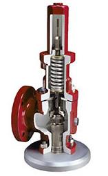
2600 Series ConstructionResistance to Discharge Piping StrainsFor most pressure relief valves, and particularly for those from which thedischarge must be piped away to a remote location, it is almost impossibleto keep piping strains away from the valve. The superior Farris pressurerelief valve design incorporates several features which allow this valve totake a maximum amount of piping strain without hampering the functionalcharacteristics of the valve or contributing to serious leakage.1.The threaded connection between the valve nozzle and the valve inletflange is located low in the flange so that any distortion which may takeplace at the inlet neck of the body is not transmitted to the valve nozzle.This eliminates the effect of the distortion on the nozzle seating surfaceand the subsequent serious leakage through the valve (Fig 3).2.The accurate guiding in the Farris design, using the double universalball joint construction above and below the sleeve guide, will allow thedisc seat to align itself positively with the nozzle seat in cases wherethe discharge piping strains cannot be avoided and have forced theupper portion of the valve out of exact alignment (Fig 4 & 5).3.The superior strength built into the body of the Farris pressurerelief valve to resist these discharge piping strains materiallyreduces the deflection and distortion in the valve and reducesthe leakage encountered, when at times discharge piping strainsbecome excessive.In spite of these features, however, it is advisable to minimize thedischarge piping strain on any pressure relief valve. It is our recommendation that piping engineers eliminate these discharge piping strains asmuch as possible under all operating conditions. Additional information onallowable external loads is provided in the Farris Technical Recommendations publication.
Isolation of Bonnet Spring ChamberThe Farris pressure relief valve huddling chamber is engineered to extractthe flow forces required to overcome the force of the spring as well asthe forces resulting from the body and bonnet pressure when the valve isopen. In other designs, the use of eductor tubes, venting the guide directlyinto the valve body, or other techniques are used in an attempt to keep thehuddling chamber or body pressure away from the topside of the disc toobtain full lift and capacity. These designs may have undesirable effects onvalve performance, life and maintenance. Special attention should be givenin the following cases:
1.High Temperature. In Farris pressure relief valves on high temperatureservice, there is no induced or forced flow of the hot lading fluid intothe bonnet spring chamber, so relaxation of the spring due to hightemperature does not occur as rapidly as it does in other valve designs.As a result, blow down in the Farris valve is stabilized for longer flowingperiods than in competitive designs.
If connected to a closed system, specific care should betaken to keep piping strains away from the pressure reliefvalve under all conditions of process operation.
Figure No. 42.Corrosive Service. In Farris pressure relief valves on corrosive service,there is no induced or forced flow of the corrosive lading fluid past theguiding surfaces during valve operation. This reduces the corrosiveeffect of the lading fluid on the guiding surfaces and valve spring, solowering the frequency of galling and spring failure with the accompanying reduction of maintenance costs and unscheduled down time.3.Dirty Service. Where small foreign particles can be carried in the gasor vapor stream, there is no induced or forced flow in the Farris designcarrying these small particles between the guiding surfaces. Galling ofthe guide surfaces, which frequently causes the valve to hang orfreeze in either an open or closed position, is eliminated.The Farris design avoids all these difficulties by discharging directly fromthe huddling chamber into the valve body without inducing flow past theguiding surfaces into the spring chamber or forcing flow past the guidingsurfaces because of the large pressure drop between the huddlingchamber and the valve body.
2600 Series MetallurgyIntegral Sleeve GuideThe Farris pressure relief valve design incorporates an integral sleeveguide (Fig 5), assuring continual positive alignment after the part has beenmanufactured, and including the same high corrosion resistant propertiesin the guide flange that are present in the sleeve portion of the guide. Thesleeve guide is extended above the top of the guide flange, minimizing thepossibility of corrosive or other foreign particles washing onto the guidingsurfaces when the valve is relieving or when it is breathing as a resultof atmospheric temperature changes. Openings are provided in the guideflange to allow these solid particles to leave the bonnet, preventing themfrom passing between the guiding surfaces and causing galling.
Optimum Seating Surface Finish. Seat surfaces are machine lapped andpolished to produce flatness (as measured with optical flats) that deviatesless than eleven millionths of an inch from a true plane, with a surfacefinish of five micro inches or less. Regardless of the seating surfaces,maximum tightness will not be achieved unless positive alignment andelimination of thermal distortion are integral design features of the valve.
TightnessIn a spring loaded pressure relief valve, the force exerted by the systempressure under the valve disc approaches the opposing spring force on topof the valve disc as the system operating pressure nears the set pressureof the valve. Since the operating pressure of the system is often 90% ofthe valve set pressure, the differential force holding the seats together isquite small.There are several factors which affect the tightness of the spring loadedpressure relief valve, including alignment, disc strength, thermal distortion,and preparation of seating surfaces. The Farris valve is engineered forexceptional tightness because of positive alignment, a high strength discdesign, the elimination of thermal distortion and optimum seating surfacefinish.
Positive Alignment. Using the double universal joint, 2-1/2 to 1 guidingratio, and self-aligning disc, positive alignment of internal parts isachieved. Misalignment is avoided, improving tightness and eliminatingother undesirable effects such as long blow down.High Strength Disc Design. In the Farris valve, the thickness of the selfaligning disc (Fig 6) is no greater than necessary; however, the samethickness is maintained for all catalog materials. For purposes of strength,the disc is strong enough in bending moment for all materials shown inthe catalog. Valves constructed with hardened discs are exceptional inwithstanding the effects of impact, an advantage where installation orprocess conditions may cause chatter.
Elimination of Thermal Distortion. In a pressure relief valve, especiallyon high or low temperature service, a single large disc, with its top surfaceexposed to atmospheric temperature when the valve is closed, has atemperature gradient between the surface contacted by the lading fluidand the surface contacted by the ambient temperature in the valve bodyor bonnet. This temperature gradient induces thermal stresses in a heavydisc that can cause deformation of the seating surfaces and consequentleakage of the valve.The Farris self-aligning disc is essentially encased in a disc holder withcontact at only one central point, so that the conduction or convection ofheat around the disc is quite low. As a result, the thermal stresses at theseating surface practically disappear. This gives further assurance oftightness over the range of temperatures used in various operations.
2600 Series OperationAll Stainless Steel Stem ConstructionThe Farris pressure relief valve design features an all stainless steel stem.This construction cost-effectively eliminates dangerous sticking due togalvanic corrosion at the upper guiding point in the spring adjusting screw.The careful design of this upper bearing also ensures proper alignmentand optimum freedom from galling and erratic popping.
Positive Connection of PartsThe Farris design incorporates a positive connection between the valvestem and the stem retainer as well as between the disc and disc holder(Fig 7). These connections are made with a male threaded head whichthreads into a portion of a female socket through which it drops freeinto an undercut chamber to make bearing contact on a sphericalsurface. This allows complete freedom of action for alignment purposeswhile retaining the positive connection of the threads. It also eliminatesthe need to use snap ring connections which, in some cases, are notsufficiently positive during valve operations and may be inadvertentlyleft out during maintenance.
Convertibility of DesignThe Farris pressure relief valve is available as a conventional valve and asa BalanSeal (balanced bellows) valve. The conversion of this valve fromconventional to BalanSeal, or vice versa, requires only the addition orremoval of the balanced bellows and bellows gasket in the valve, and thecoincidental removal or replacement of a pipe plug in the valve bonnetvent. No other parts are required and all other parts are completelyinterchangeable. This unique feature is offered in orifices F through T.In addition, the bonnet of the valve is constructed so that all valves can beequipped with a plain screwed cap, bolted cap, an open lever or packedlifting lever without changing any other valve parts or fully disassemblingthe valve.
The Farris two-piece design of disc holder and stem retainer features apositive locking device called the disc holder lock screw. Any attempt todisassemble these parts causes the lock screw to lock tighter, unless firstdisengaged. The lock screw provides a positive lock between these twoparts that makes them equivalent to a single part but without theassociated disadvantages. The two-piece assembly allows conversion tobellows construction at a minimal investment. The two-piece design alsoallows the stem retainer to be constructed of less corrosion-resistantmaterial than the disc holder, when a bellows is installed to isolate themoving parts. When maintenance requires parts replacement, the entireassembly will not need replacement if only one piece is damaged.
Although the Farris pressure relief valve does not induce circulation of thelading fluid through the bonnet, the bonnet and the valve body are made ofthe same high quality steel. It is important that both the body and bonnetbe made of materials suitable for the service in which the valve will beused, especially in the case of high temperature services.
2600 Series OperationSteam Jacketing for Better Heat TransferIn modern process plants, it is necessary to keep some valves and lineswarm at all times to avoid solidification of the lading fluid and to guaranteethe safety of equipment. Farris offers a steam jacket (Fig 8) to substantiallyincrease the rate of heat transfer into the valve and, at the same time,simplify the problem of removing or dismantling the valve for maintenance.This design offers a separate two-piece jacket that installs on a standardvalve body. See details on page 71.
Simple, Accurate AdjustmentsThe single Blow Down Ring construction of the Farris pressure relief valveallows simple shop or field setting, something not possible with multiplering valve types.In most process plants, it is not possible or economical to test the pressurerelief valve in place on the process equipment, so the valve is tested whilemounted on a maintenance shop test stand where the pressure andvolume for testing are often limited. With the Farris design, the single BlowDown Ring is adjusted in the maintenance shop so that the set pressurepoint can be observed. After the set pressure is established, the BlowDown Ring is adjusted to a lower empirically predetermined or fieldestablished position depending on set pressure, size and lading fluid (Figs9A, 9B). Blow Down Ring settings and test equipment recommendationsare detailed in maintenance manuals published by Farris Engineering.
Interchangeability of PartsIn the Farris pressure relief valve design, maximum interchangeability ofparts is maintained in order to reduce the number of spare parts neededand keep spare parts inventories to a minimum.
General Technical InformationStandard Flanged Connections1.All steel raised face flanges are supplied with a serrated spiral finish with45 to 55 grooves per inch and a finish between 125 and 160 AARH.2.All ring joint flanged facings are supplied for octagonal or oval gaskets.3.Facings other than raised face or large male can be supplied atadditional cost.4.Flange ratings that conform to ANSI B16.5 are indicated on each OrificeSelection Table. Heavier outlet flanges can be supplied at additional cost.For flange dimensions, see ANSI Dimension Table, page 77.5.Drilling of all flanges always straddles the valve center line.
Valve TrimTrim is a term that generally refers to internal parts of a pressure reliefvalve. Unless noted, valve trim in a Farris pressure relief valve specificallyincludes the nozzle and disc only. Standard bills of materials for all 2600Series valves are located on pages 12 and 13. For low temperature andcorrosive service materials, see pages 17 through 21. If other thanstandard trim or metallurgy is required, this must be specified.
Differential Between Operating and Set PressureFor best performance in process applications, we recommend pressurerelief valves be set to open at a minimum of 10% or 25 psig above theoperating pressure. A suitable margin above the operating pressure shouldbe provided in order to prevent any unintended operation of the pressurerelief valve. Refer to ASME Section VIII Pressure Vessel Code, Appendix M,Paragraph M-10, Pressure Differentials for Pressure Relief Valves as wellas to Farris Technical Recommendations for complete information.In the case of pump and compressor discharge lines, a greater differentialis recommended if possible, since pulsations within the system can resultin faulty valve operation. Consequently, the pressure relief valve should beset as high above the discharge line pressure as possible.
Set Pressure Compensation for TemperatureAn increase in temperature causes a reduction of valve set pressure asa result of the direct effect of temperature on the spring and expansionof body and bonnet which reduces spring loading. Since pressure reliefvalves are invariably tested at atmospheric temperature, it is customaryto adjust the set pressure at ambient conditions to compensate for higheroperating temperatures as indicated in the following table.
Steam service valves are tested on steam by the manufacturer and requireno additional temperature compensation. Where the set pressure is abovethe production steam test facility limits, Section VIII steam valves may betested on air. When steam valves are tested on air, compensation shown inthe All Service Fluids Table should be used.
Low Pressure SettingsLow set pressure limits are indicated in the following table. These limitsapply to both metal-to-metal and Oring seat construction. Low pressuresettings may be governed by valve design and performance and/or Codeapplication limits. Pressure vessels having operating pressures notexceeding 15 psig are not considered within the scope of the ASME Code,Section VIII. Accordingly, pressure relief valve requirements for suchapplications are governed by other Codes and Standards that shouldbe consulted.The sizing equations for compressible fluids provided herein are valid forsonic flow conditions and should not be used to size pressure relief valvesfor applications in which subsonic (below 15 psig) flow conditions mayexist. Low pressure applications can be reviewed by the Factory andspecial valves provided to meet those requirements.
DefinitionsSafety Valve an automatic pressure relieving device actuated by thestatic pressure upstream of the valve, and characterized by rapid fullopening or pop action. Used for steam, gas or vapor service.Relief Valve an automatic pressure relieving device actuated by thestatic pressure upstream of the valve, which opens in proportion to theincrease in pressure over the opening pressure.Safety Relief Valve an automatic pressure actuated relieving devicesuitable for use as either a safety or relief valve, depending on the application.Pressure Relief Valve a pressure relief device designed to re-close andprevent the further flow of fluid after normal conditions have been restored.Set Pressure in pounds per square inch gage, the inlet pressureat which the pressure relief valve is adjusted to open under serviceconditions. In a safety or safety relief valve in gas, vapor or steamservice, the set pressure is the inlet pressure at which the valve popsunder service conditions. In a relief or safety relief valve in liquid service,the set pressure is the inlet pressure at which the first steady steamflows from the valve perpendicular to the outlet.Differential Set Pressure the pressure differential, in pounds per squareinch between the set pressure and the constant superimposed backpressure. It is applicable only when a conventional type safety relief valveis being used in service against a constant superimposed back pressure.Cold Differential Test Pressure in pounds per square inch gage is theinlet static pressure at which the pressure relief valve is adjusted to openon the test stand. This pressure includes the corrections for serviceconditions of back pressure or temperature, or both.
Overpressure a pressure increase over the set pressure of a pressurerelief valve, usually expressed as a percentage of the set pressure.Accumulation the pressure increase over the maximum allowableworking pressure of the vessel during discharge through the pressurerelief valve, expressed as a percent of that pressure or in pounds persquare inch.Blow down the difference between actual popping pressure of apressure relief valve and actual reseating pressure, expressed as apercentage of set pressure or in pressure units.Lift the actual travel of the disc away from closed position when a valveis relieving.Back Pressure the static pressure existing at the outlet of a pressurerelief device due to pressure in the discharge system.Constant Back Pressure back pressure that does not changeappreciably under any condition of operation whether the pressure reliefvalve is closed or open.Variable Back Pressure refer to the discussion on BalanSeal valves onpage 85.Built-Up Back Pressure pressure existing at the outlet of a pressurerelief device occasioned by the flow through that particular device into adischarge system.Superimposed Back Pressure the static pressure existing at the outletof a pressure relief device at the time the device is required to operate. It isthe result of pressure in the discharge system from other sources.
Type Numbering SystemOur type numbering system simplifies the selection and specifying of Farris pressure relief valves because the digits that comprise a specific type numberhave a distinct significance. The digits describe the basic valve series, orifice, seat and internal construction, inlet temperature range, body, bonnet andspring material, inlet flange class and Code liquid design.
* Temperature ranges 4 and 5 are beyond thescope of this catalog. Consult the Factory.** Temperature range 2 is no longer used as thestandard range valve handles temperatures to800F.
Valves If an exact replacement valve is required, then the valve type,size and serial number must be specified to ensure proper dimensionsand material being supplied. If a specific valve is obsolete, a recommendation of the current equivalent will be made if possible.
Spare Parts When ordering parts, use part names as listed in the bills ofmaterials. Specify valve type, size and serial number. If the serial numberis not available, the original Farris factory order number will help us supplythe proper part and material.Springs Order as an assembly to include spring with upper and lowerspring buttons. Specify valve type, size, serial number, set pressure andbackpressure, if any.Note: If valve modification or set pressure changes are required, consideration must begiven to correct the nameplate and other data.
A Expanded API sizes: air,steam and gas service*B Expanded API sizes: ASMEliquid valve*C Expanded API sizes: ASME150Code Section VIII exposed300 lightweightspring design*valveDValve suitable for heat300 heavyweighttransfer service-vaporvalveEValve suitable for heat600transfer service-liquid900F Expanded API size valves1500suitable for heat transferservice-vapor*2500G Expanded API size valvessuitable for heat transferservice-liquid*L ASME Code certified forliquid service onlyS ASME Code Section VIIIexposed spring design
2600L Series Certified DesignThe 2600L Series liquid relief valves are for use on ASME Section VIII Codeapplications and offer a superior valve with greater capacity at 10%overpressure than the traditional 2600 Series.The 2600L Series complements a full line of pressure relief valves inorifices D through T to meet the ASME Code requirements forincompressible fluid services. The Code stamped construction requiresliquid relief valves that have been capacity certified on water at 10%overpressure to carry the ASME UV and National Board NB symbols.For compressible fluid services, the standard 2600 Series should be used.Liquid service applications that do not require the use of Code stampedliquid relief valves can still be satisfied with the standard 2600 series line.In most cases the standard 2600 should only be used in liquid servicewhere an existing installation pipe size / orifice combination does notmatch the 2600L design.The 2600L Series is also certified under ASME Code Section VIII for use inair, gas, steam, and vapor services. It may be used in those applications orwhere two phase or flashing fluid service is anticipated. The 2600L iscertified as a fixed blow down design whether used in compressible ornon-compressible services.The type number is differentiated from the existing 2600 Series design byadding the letter L as a suffix. The letter L is used to specify all liquidtrim type numbers and always appears in the seventh position of the typenumber, just before the three-digit option code for inlet facing/capconstruction/test gag. Example: 26GA10L-120.Optional trim material classes and other accessories are available, as withthe 2600 Series, with the exceptions of the H2600. All types within the2600L Series follow the s


 8613371530291