
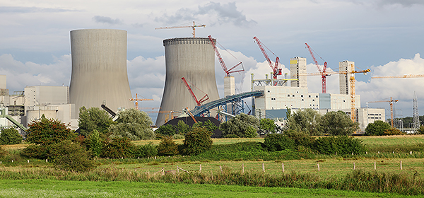
fisher safety valve factory

We know the consequences of process failure are great, that’s why we have an unwavering commitment to standards and processes that ensure innovative and reliable product designs. Many years from now, as the Fisher™ brand is put onto products, customers will continue to know it stands for integrity.

Industry leading pressure and safety relief valve designs with over 140 years of technical and application expertise providing custom engineered solutions for O&G, Refining, Chemical, Petrochemical, Process and Power applications. Our designs meet global and local codes and standards (API 526; ASME Section I, IV & VIII; EN ISO 4126; PED & more). Gain insight into the performance of your pressure relief valves with wireless monitoring.

Fisher Types 1808 globe-style and 1808A angle-style pilot-operated backpressure regulators or relief valves are economical, compact devices used in gas or liquid service to maintain pressure on oil and gas separators, and in pressure relief applications in gas distribution systems.

The Fisher 1805-16 Series Backpressure Regulator / Relief Valve designed for use where a relief valve is needed between the first-stage and second stage-stage regulators. This series of relief valves are suitable for natural gas, air, propane or any medium compatible with the internal valve parts. Relief pressures range from 5 to 125 psig / 0,34 to 8,6 bar. Maximum pressure, including buildup is 150 psig / 10,3 bar.

The Fisher Type 289H-2 Backpressure Regulator/Relief Valve is a throttling relief valve used downstream of pressure regulators to protect the downstream system from overpressure.

The human heart has four valves that control blood flow through the body. Industrial valves act in a similar manner and control how fluid flows through a pipe or a duct. There are many different types of valves used for various applications and it is extremely important that the valve is made of the correct materials. The article explained how valves may need to stand high pressure or may have caustic fluids flowing through them that will eventually corrode the material. If a pressure relief safety valve blows on a steam boiler, there could be injuries to employees. Leaks in safety valves used in gas or vapor situations could cause environmental hazards. In the oil and gas industry, there are valves not only throughout the pipelines, but also on storage tanks to control fugitive emission losses that can result from handling flammable and hazardous petroleum products that produce vapor.
Liquids and other media flowing through valves during critical operating conditions can be affected by a number of hazards…. The symptoms of valves that may be failing include an increase in noise emission, valve and pipe component erosion, or mechanical vibration in the valves and the connected pipelines. Under many critical applications, neglecting these signs can result in negative outcomes on plant performance, the costs of ownership, fugitive emissions, and even serious safety hazards. This why many safety valves are required to be made to ASME, ANSI, and/or API standards.
Industries that use safety valves in their operations must remember, however, that valves are affected in the same way as pipes. Fluids are not only passing through them but there is also pressure on the materials when safety valves are open and closed, which could lead to greater or more rapid corrosion. So verifying metal alloys is essential to manufacturing quality assurance. If you are the one producing the valves, you need to ensure that the products that go out the door match the customer’s specifications and meet industry standards. Is the metal or alloy correct? Are you sure? Your reputation and brand depend on it. If you are the one using the valves, you better make certain that the incoming product matches your specifications. Lives could depend on it. And if your company relies on those valves to keep operations running smoothly, you better have a maintenance schedule in place to make sure that there has been no degradation over time.
Portable x-ray fluorescent (XRF) analyzers are essential tools for verifying that all critical metals conform to requirements independent of certifications and markings from the manufacturer. They can identify material other than that specified and help ensure product reliability and safety. These x-ray fluorescence analyzers are used for in-house QA/QC of alloy materials, coating/plating thickness verification, positive material identification of incoming alloy raw material stock, machined and fabricated parts and wear metals in oil. They give users immediate, nondestructive chemical analysis and alloy grade identification – which can help avoid hazards.
No matter what industry, material verification and positive material identification of the metal alloys used in valves has never been more important for product reliability and safety. After all, what good is a safety valve if it’s not very safe.
Type MR98H is a direct-operated relief valve for use on relief and backpressure applications involving large LPG pumping systems and vaporizers. Internal pressure registration eliminates the need for a control line. It is available in sizes from 1/2 in. to 1 in., relief pressure ranges from 15 to 200 psi. The MR98HH is a 1" size with relief pressure range from 150 to 375 psi.

Quiet Operation—The Whisper Trim™ cage option can reduce noise from high-velocity gas by as much as 10 decibels. Whisper Trim equipped regulators are especially engineered for high-pressure applications where sonic gas velocities are often encountered at relief valve outlets.
Stable Startup—The unique hollow valve stem in the pilot provides quick pressure registration on top of the main valve plug preventing main valve unseating during normal system startup.
UL Listed external relief valves used on ASME containers. The relief valve is held close by the spring force seating the rubber valve disc against the orifice. When the tank pressure exceeds the spring force, the valve disc lifts off the orifice allowing gas to discharge through the valve to the air. When the tank pressure decreases enough, the spring force closes the valve disc back against the orifice stopping further discharge. All working parts of theses valves are outside the container connection so they must be protected against mechanical damage.
Economical: Low initial cost, easy installation, and high capacity per dollar invested reduces total cost of having relief valve capabilities in your system
Durable: Brass body construction and stainless steel spring reduce susceptibility to corrosion damage and the preset, pinned spring retainer prevents relief valve setpoint tampering

The Series 500 is a modulating, soft-seated pilot operated valve offering premium tightness with the ability to handle temperatures from -65°F to 515°F (-54°C to 268°C). It is designed to decrease leakage associated with metal-seated safety relief valves under extreme operating temperature conditions.
.jpg)
H200 Series Relief Valves Figure 1. External View of H200 Series Relief Valve Figure 2. Sectional View of H200 Series Relief Valve The H200 Series Pop™ relief valves, Figures 1 and 2, are self-operated relief valves with preset and pinned spring retainers. The inlet pressure registers directly on a spring-opposed poppet assembly which includes a Nitrile (NBR) disk. When the inlet gas pressure increases above the spring setting, the poppet and disk assembly is pushed away from the orifice. Springs are available that provide any relief pressure setting from 25 to 300 psig / 1.7 to 20.7 bar. • Space-Saving Construction - Small relief valve size allows installation where space is limited. With this simple operation and wide spring setting selection, the H200 Series Pop relief valves may be used where venting to atmosphere is acceptable, where the process gas is compatible with the Nitrile (NBR) disk, where its relief capacity is adequate and where some pressure relieving tolerance is acceptable. Common applications include use on pneumatic control lines of air drills, jackhammers and other similar equipment and on farm tap installations. The H200 Series is comprised of the Types H202 and H203 relief valves with the difference being in the inlet connection size. • conomical - Low initial cost, easy installation E and high capacity per dollar invested reduces total cost of having relief valve capabilities in your system. • urable - Brass body construction and stainless D steel spring reduces susceptibility to corrosion damage and the preset, pinned spring retainer prevents relief valve setpoint tampering. Installation This relief valve may be installed in any position but must be oriented so that gas discharged from the valve does not create a fire, toxic or explosion hazard. The relief valve should be protected from material and conditions that could clog the outlet side of the valve and affect the venting of gas. A typical installation is shown in Figure 3. A Type P145 raincap is recommended for use with any H200 Series relief valve. Dimensions are shown in Figure 4. The relief valve and installation should be checked for compliance with all

It depends. Some of the valves we carry run between $100-$200, as they are suitable for smaller applications. Some industrial settings may need larger or more robust valves, which can run upwards of $1,000 or $2,000.
We recommend that your maximum expected operating pressure will not exceed 90% of the valve’s set pressure. This helps to ensure the valve’s seat will stay tight.
Identifying the process media, or service, of a valve is important to set pressure. If a valve has the correct set pressure but is used on the wrong application, there’s a chance the valve won’t open when needed. This could cause an overpressure event.
No. The valve’s set pressure is measured in gauge pressure, or pounds per square inch gauge (psig), so you don’t have to take altitude into account when selecting your valve.
Back pressure can have complex effects on a valve’s set pressure, capacity, and overall performance. If you know your application will have any type of back pressure, we recommend getting in touch with one of our specialists to verify how it may affect your valve selection or performance.
When you’re shopping on Valves Depot or looking at a valve nameplate, you might see references to ASME Sections I (V stamp), IV (HV stamp), or VIII (UV stamp) in the valve specs. These refer to the ASME (American Society of Mechanical Engineers) Boiler and Pressure Vessel Code (BPVC) standard, a set of guidelines for valve manufacturing.
When you’re installing a smaller valve, preventing damage is as simple as handling the new valve with care. Some parts are fragile. But for larger, heavier valves, during installation, pay close attention to the lever — make sure your lifting straps don’t accidentally wrap around or otherwise conflict with it.
After your initial inspection, schedule maintenance every two to six months. Your maintenance interval will depend on your service conditions and the age of the valve.
Some valve models are required to have a drain hole per the ASME Boiler and Pressure Vessel Code. The drain hole helps prevent condensate from accumulating in the body that could freeze or corrode internal valve parts.
Just because your valve is leaking doesn’t necessarily mean that you need a new valve or repairs — you may need to adjust your operating procedures. Lowering your system pressure, accounting for expected pressure spikes, and regularly calibrating your gauges are a few possible ways to help stop or prevent leakage.


 8613371530291