
flow safety valve free sample
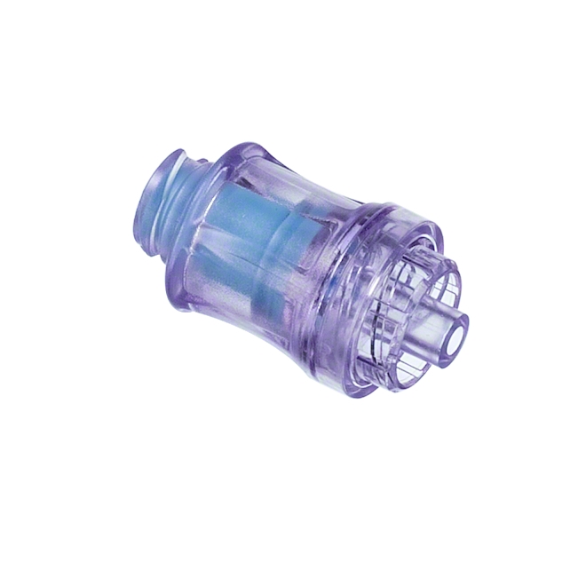
Find check safety valve on Microchek.com. The system is available in a variety of polymers and elastomers to ensure compatibility with most liquids and gases. We can select valves that fall into a specific cracking pressure range if needed. We want the opportunity to help you solve your flow control applications and we can build special configurations. Relief valves are used to hold a fluid circuit or reservoir at a positive or negative pressure. Our staff is available to advise you on your applications. Please ask for a FREE sample that meets your needs. If your design requires a unique configuration, we will be pleased to quote your needs. Related terms include idle control valve location, 2-phase steam relief valve, closet flange check valve, double a relief valve qbj, and consolidated relief valve 1905jc-31-gs. Call us for a FREE check valve sample. 1-800-780-0008 Or fax us at 1-800-622-0002. The Microchek system incorporates this cartridge and a wide selection of end pieces to accommodate most connection requirements. This valve is the heart of our system and has a great design.
Microchek is a company with an expertise in cartridge check valves. Check safety valve related phrases are on Microchek.com. The Microchek valve is a cartridge check valve incorporating an innovative guided poppet design. The Microchek valve has a low pressure drop and can be specified with a wide variety of cracking pressures. Other phrases include closet flange check valve, double a relief valve qbj, idle control valve location, consolidated relief valve 1905jc-31-gs, 2-phase steam relief valve. This vaulve may be used alone or as the central component of the system. We offer competitive pricing and reliability because we are the manufacture. Parts are molded and assembled in the U.S. Look for check safety valve on Microchek.com. The Microchek valve incorporates our innovative check valve module with ultrasonically welded end pieces. Microcheks innovative designs use a minimum number of parts to assure reliability through simplicity. Related phrases are 2-phase steam relief valve, consolidated relief valve 1905jc-31-gs, idle control valve location, closet flange check valve, and double a relief valve qbj. The Microchek valve has a low pressure drop and can be specified with a wide variety of cracking pressures.
Check safety valve is related to Microchek.com. We offer competitive pricing and reliability because we are the manufacture. Parts are molded and assembled in the U.S. Call us for a FREE check valve sample. 1-800-780-0008 Or fax us at 1-800-622-0002. This valve is the heart of our system and has a great design. The Microchek valve is a cartridge check valve incorporating an innovative guided poppet design. Other phrases are closet flange check valve, consolidated relief valve 1905jc-31-gs, double a relief valve qbj, 2-phase steam relief valve, and idle control valve location. We want the opportunity to help you solve your flow control applications and we can build special configurations. We can select valves that fall into a specific cracking pressure range if needed. This vaulve may be used alone or as the central component of the system. Our staff is available to advise you on your applications. Please ask for a FREE sample that meets your needs. Microcheks innovative designs use a minimum number of parts to assure reliability through simplicity. The Microchek valve incorporates our innovative check valve module with ultrasonically welded end pieces.

Pressure relief valve is related to Microchek.com. We offer competitive pricing and reliability because we are the manufacture. Parts are molded and assembled in the U.S. The Microchek system incorporates this cartridge and a wide selection of end pieces to accommodate most connection requirements. The Microchek valve is a cartridge check valve incorporating an innovative guided poppet design. Relief valves are used to hold a fluid circuit or reservoir at a positive or negative pressure. We can select valves that fall into a specific cracking pressure range if needed. The Microchek valve has a low pressure drop and can be specified with a wide variety of cracking pressures.
The Microchek valve is a cartridge check valve incorporating an innovative guided poppet design. Relief valves are used to hold a fluid circuit or reservoir at a positive or negative pressure. We want the opportunity to help you solve your flow control applications and we can build special configurations.
A safety valve must always be sized and able to vent any source of steam so that the pressure within the protected apparatus cannot exceed the maximum allowable accumulated pressure (MAAP). This not only means that the valve has to be positioned correctly, but that it is also correctly set. The safety valve must then also be sized correctly, enabling it to pass the required amount of steam at the required pressure under all possible fault conditions.
Once the type of safety valve has been established, along with its set pressure and its position in the system, it is necessary to calculate the required discharge capacity of the valve. Once this is known, the required orifice area and nominal size can be determined using the manufacturer’s specifications.
In order to establish the maximum capacity required, the potential flow through all the relevant branches, upstream of the valve, need to be considered.
In applications where there is more than one possible flow path, the sizing of the safety valve becomes more complicated, as there may be a number of alternative methods of determining its size. Where more than one potential flow path exists, the following alternatives should be considered:
This choice is determined by the risk of two or more devices failing simultaneously. If there is the slightest chance that this may occur, the valve must be sized to allow the combined flows of the failed devices to be discharged. However, where the risk is negligible, cost advantages may dictate that the valve should only be sized on the highest fault flow. The choice of method ultimately lies with the company responsible for insuring the plant.
For example, consider the pressure vessel and automatic pump-trap (APT) system as shown in Figure 9.4.1. The unlikely situation is that both the APT and pressure reducing valve (PRV ‘A’) could fail simultaneously. The discharge capacity of safety valve ‘A’ would either be the fault load of the largest PRV, or alternatively, the combined fault load of both the APT and PRV ‘A’.
This document recommends that where multiple flow paths exist, any relevant safety valve should, at all times, be sized on the possibility that relevant upstream pressure control valves may fail simultaneously.
The supply pressure of this system (Figure 9.4.2) is limited by an upstream safety valve with a set pressure of 11.6 bar g. The fault flow through the PRV can be determined using the steam mass flow equation (Equation 3.21.2):
Once the fault load has been determined, it is usually sufficient to size the safety valve using the manufacturer’s capacity charts. A typical example of a capacity chart is shown in Figure 9.4.3. By knowing the required set pressure and discharge capacity, it is possible to select a suitable nominal size. In this example, the set pressure is 4 bar g and the fault flow is 953 kg/h. A DN32/50 safety valve is required with a capacity of 1 284 kg/h.
Where sizing charts are not available or do not cater for particular fluids or conditions, such as backpressure, high viscosity or two-phase flow, it may be necessary to calculate the minimum required orifice area. Methods for doing this are outlined in the appropriate governing standards, such as:
The methods outlined in these standards are based on the coefficient of discharge, which is the ratio of the measured capacity to the theoretical capacity of a nozzle with an equivalent flow area.
Coefficients of discharge are specific to any particular safety valve range and will be approved by the manufacturer. If the valve is independently approved, it is given a ‘certified coefficient of discharge’.
This figure is often derated by further multiplying it by a safety factor 0.9, to give a derated coefficient of discharge. Derated coefficient of discharge is termed Kdr= Kd x 0.9
Critical and sub-critical flow - the flow of gas or vapour through an orifice, such as the flow area of a safety valve, increases as the downstream pressure is decreased. This holds true until the critical pressure is reached, and critical flow is achieved. At this point, any further decrease in the downstream pressure will not result in any further increase in flow.
A relationship (called the critical pressure ratio) exists between the critical pressure and the actual relieving pressure, and, for gases flowing through safety valves, is shown by Equation 9.4.2.
Overpressure - Before sizing, the design overpressure of the valve must be established. It is not permitted to calculate the capacity of the valve at a lower overpressure than that at which the coefficient of discharge was established. It is however, permitted to use a higher overpressure (see Table 9.2.1, Module 9.2, for typical overpressure values). For DIN type full lift (Vollhub) valves, the design lift must be achieved at 5% overpressure, but for sizing purposes, an overpressure value of 10% may be used.
For liquid applications, the overpressure is 10% according to AD-Merkblatt A2, DIN 3320, TRD 421 and ASME, but for non-certified ASME valves, it is quite common for a figure of 25% to be used.
Backpressure - The sizing calculations in the AD-Merkblatt A2, DIN 3320 and TRD 421 standards account for backpressure in the outflow function,(Ψ), which includes a backpressure correction.
Two-phase flow - When sizing safety valves for boiling liquids (e.g. hot water) consideration must be given to vaporisation (flashing) during discharge. It is assumed that the medium is in liquid state when the safety valve is closed and that, when the safety valve opens, part of the liquid vaporises due to the drop in pressure through the safety valve. The resulting flow is referred to as two-phase flow.
The required flow area has to be calculated for the liquid and vapour components of the discharged fluid. The sum of these two areas is then used to select the appropriate orifice size from the chosen valve range. (see Example 9.4.3)
Many standards do not actually specify sizing formula for two-phase flow and recommend that the manufacturer be contacted directly for advice in these instances.

An OSHA COMPRESSED AIR SAFETY SHUT-OFF VALVES should be placed immediately after the air control shut off valve and before the hose on a compressor, and after each discharge port that a hose is connected to.
Before starting the compressor the air control valve should be closed completely. When the compressor unloads, open the air shut off control valve very slowly. Full port ball valves tend to work better than gate or butterfly type valves.
The air shut off control valve must be fully open for the OSHA COMPRESSED AIR SAFETY SHUT-OFF VALVES to work. Some portable air compressor manufacturers recommend start-up with the air control valve slightly open. In this case you may have to close the valve and reopen it slowly to the full open position, or wait for the safety shut-off valve to reset itself.
If the OSHA COMPRESSED AIR SAFETY SHUT-OFF VALVES fails to operate despite meeting all condi-tions, check the hose line for obstructions or a hose mender restricting normal air flow.
• Turn on air supply slowly (to avoid tripping OSHA safety valve). Prior to fully reaching operation conditions, the OSHA COMPRESSED AIR SAFETY SHUT-OFF VALVES should suddenly activate and stop air flow.
• If the OSHA COMPRESSED AIR SAFETY SHUT-OFF VALVE is not activated the unit should be disconnected and the lower flow range OSHA COMPRESSED AIR SAFETY SHUT-OFF VALVES should be used. This means you need to use a different valve with a lower scfm range.
• At temperatures below 40°F ensure that OSHA COMPRESSED AIR SAFETY SHUT-OFF VALVES are not subject to icy conditions which may prevent proper functioning.

Surface-controlled subsurface safety valves (SCSSVs) are critical components of well completions, preventing uncontrolled flow in the case of catastrophic damage to wellhead equipment. Fail-safe closure must be certain to ensure proper security of the well. However, this is not the only function in which it must be reliable—the valve must remain open to produce the well. Schlumberger surface controlled subsurface safety valves exceed all ISO 10432 and API Spec 14A requirements for pressure integrity, leakage acceptance criteria, and slam closure.
Through decades of innovation and experience, Schlumberger safety valve flapper systems are proven robust and reliable. The multizone dynamic seal technology for hydraulic actuation of subsurface safety valves is a further improvement in reliability performance when compared with traditional seal systems in the industry.
The multizone seal technology is currently available in the GeoGuard high-performance deepwater safety valves, which is validated to API Spec 14A V1 and V1-H.
Safety anti-water backflow function to guarantee the proper working of the water heating tank; High-quality stainless steel spring ensures better working performance and also the long using life;
Safety relief valves are safety devices used to automatically release pressure from a system. A valve is installed at the end of a pipe, and it opens when the pressure in the pipe gets too high. The function of this device is to protect both people and equipment from potential damage that an overpressurized system can cause. 12 types of safety relief valves, so you will know what kind you need for your business or home!
Each type of valve has its own unique set of benefits and drawbacks, so choosing the right one for your specific needs is important. For example, a thermal expansion valve is perfect for systems subject to wide fluctuations in temperature. At the same time, a spring-loaded safety relief valve is ideal for systems that have a low-pressure ceiling. Make sure you consult with a professional before making your final decision!
-Pressure reducing and regulating stations pressure-sensitive discs. Each type of valve has its own unique set of benefits and drawbacks, so choosing the right one for your specific needs is essential. For example, a thermal expansion valve is perfect for systems subject to wide fluctuations in temperature. At the same time, a spring-loaded safety relief valve is ideal for systems that have a low-pressure ceiling.
The Non-Return Safety Relief Valve is a safety device that prevents the backflow of water into the water tank. Its primary function is to prevent the backflow of water from the tank. Its secondary position is to relieve excess pressure in the system by allowing some flow out of the relief valve when needed.
The Non-Return Safety Relief Valve is designed to work in a water tank. The valve has a float inside it, rising and falling as the water level changes. When the float reaches a certain point, it closes off the pipe leading from the tank to your house so that no more water can get out of the tank than you have already used. This prevents any overflow or leakage from occurring.

The primary purpose of a safety valve is to protect life, property and the environment. Safety valves are designed to open and release excess pressure from vessels or equipment and then close again.
The function of safety valves differs depending on the load or main type of the valve. The main types of safety valves are spring-loaded, weight-loaded and controlled safety valves.
Regardless of the type or load, safety valves are set to a specific set pressure at which the medium is discharged in a controlled manner, thus preventing overpressure of the equipment. In dependence of several parameters such as the contained medium, the set pressure is individual for each safety application.
The primary purpose of a pressure relief valve is to protect life, property and the environment. Pressure relief valves are designed to open and release excess pressure from vessels or equipment and then close again.
The function of pressure relief valves differs depending on the main type or loading principle of the valve. The main types of pressure relief valves are spring-loaded, weight-loaded and controlled pressure relief valves.
Regardless of the type or load, pressure relief valves are set to a specific set pressure at which the medium is discharged in a controlled manner, thus preventing overpressure of the equipment. In dependence of several parameters such as the contained medium, the set pressure is individual for each safety application.

Qosina offers an extensive line of medical check valves, available in an assortment of designs, in stock and ready for immediate delivery. Complete your project by choosing among our one-way duckbills, high-flow and in-line, luer-activated and dual check valves.
High-flow valves feature low flow resistance, low opening pressure and a positive seal against backflow. Designed for flushing and irrigating applications, high-flow check valves afford quick flow response for more control.
DEHP-free, acrylic in-line check valves are designed to prevent backflow and have latex-free silicone diaphragms that permit flow in one direction, thereby preventing retrograde flow (back pressure tested to their specific psi ratings). In-line check valves feature versatility in design and low cracking pressures (i.e., the pressure at which the valve will start to open). Our assortment encompasses a range of cracking pressure ratings. If back pressure is a concern, choose from our variety of duckbill check valves to help avoid backflow contamination.
Luer-activated check valves are equipped with a needle-free design featuring a closed silicone plug that blocks flow until mechanically opened with a male luer connector. Female luer lock-equipped needleless valves mate tightly with all standard luer syringes and connectors. Besides offering a high flow rate, they allow bidirectional flow for precision-controlled aspiration or injection of fluids.
Our wide selection of nearly 70 types of luer-activated valves and accessories reflects the expanding range of protocol systems utilizing this technology. With the tremendous impact of needleless systems on the safety of both patients and health professionals, they are regarded as an engineered control for prevention of infection from contaminated sharps.
Dual check valves enable injection and aspiration from separate ports of a single connector. Depending on their design, they are ideal for either the mixing of two substances, or for the mixing and continuous filling of two substances
Sourcing from a range of check valve manufacturers allows Qosina to offer numerous configuration, flow rate, material, cracking pressure and back pressure options to fit a wide range of applications. Single-use medical device check valve sample kits are also available for purchase and are ideal for testing our components with your design prior to purchase.

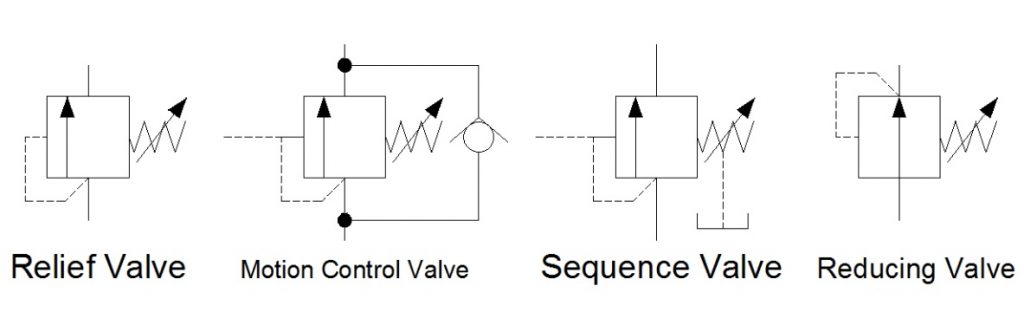
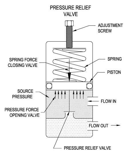
Hydraulic and pneumatic systems must regulate air or liquid pressure according to a constant pressure threshold. If the pressure exceeds the set level, it can damage equipment and create a safety hazard for workers. Pressure relief valves regulate pressure levels to prevent these dangers.
Pressure relief valves (PRVs), or back pressure regulators, reduce system pressure when it exceeds a maximum threshold. PRVs can also reduce pressure peaks that could damage equipment elsewhere in the facility. The main components of a pressure relief valve are:
When the pressure in the hose or pipe exceeds the pressure limit, will push against the diaphragm, compress the spring and open the valve. The valve opens and closes to maintain the specified pressure level. When the pressure dips below the accepted threshold, the valve closes. With adjustable PRVs, operators can adjust the spring mechanism to collapse under a higher or lower amount of pressure.
Enhances safety: PRVs were invented as a result of boilers exploding when they were not properly monitored. Thus, they are an easy and effective way to keep your system safe.
Increases efficiency: Relief valves automatically reclose when the pressure lowers to the set level, preventing excess loss of expensive gases from the system.
Materials: Most valves are made of plastic, brass, aluminum, or stainless steel. Weigh each material’s compatibility, advantages, and disadvantages relative to your system’s needs.
Operating temperature: Make sure the valve you choose can handle the expected operating temperature of your application, as the temperature can affect flow capacity and the responsiveness of the spring mechanism.
Air Logic designs and manufactures industrial pneumatic and vacuum control equipment, including preset and adjustable relief valves for medical and other applications. Our adjustable relief valves can be equipped with straight or barbed fittings. Single barbed models work best with exhaust ports that do not need a barb.
We also offer preset options, which we produce by presetting an adjustable valve at the desired pressure level. We test the valve for effectiveness before shipping it to you. Our ISO 9001:2015 certification ensures high-quality, reliable products with every delivery.

As the name implies, factory preset switches, regulators, and check valves have been preset and tested in the factory before distribution. This can facilitate your needed flow rates, lower installation time, or be adjusted after assembly.
Flow Safe is a manufacturer of spring-operated and pilot-operated high-performance pressure relief devices. The Flow Safe product line is specifically designed for applications in Natural Gas Distribution, Pipeline, Aerospace, Marine, Industrial Gasses and other liquid and gas process applications.
Due to the continued escalation of raw materials as well as additional COVID-related costs, Flow Safe is announcing a list price increase effective Aug. 2, 2021. The increase will be between 8% and 10% depending on the product line.


 8613371530291