
fmea safety valve made in china

I got a safety valve and everything looked good untill i was installing the part. I am a licensed hvac contractor and have been in the field for over 10 years now. Well the safety pilot wasent staying on so i checked the thermocouple and everything was good untill i saw that the safety valve was broken from one side where the thermocouple connects. Now i have a mad costumer because i got a part that does not work
Because of different of drive source, SSV can dividedinto Hydraulic safety valve and pneumatic valve ; With thermal and high voltage explosion-proof device ; Actuators and prepare two parts of the valve, standard interface, easy replacement and maintenance .
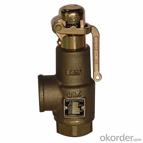
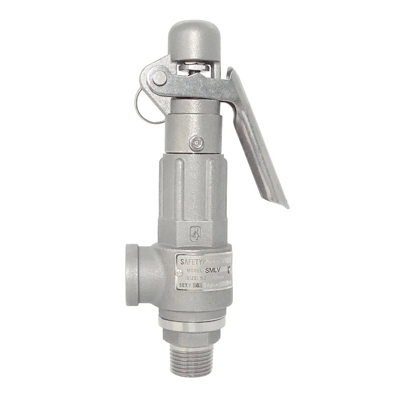
This valve is used for power plant boilers, pressure containers, pressure and temperature reducing device and other facilities. It serves to prevent the pressure exceeding the highest allowable pres-sure value and ensure the safety of the device when working.
(1)The pressure of the disc is balanced through the lever and heavy hammer and the valve is ensured seal by moving the for ton of heavy hammer and changing the weight of heavy hammer to reach the required set pressure.
(3)At the top of valve is equipped an electromagnet to open and another to close the valve. The actions of the mechanism and the electric appliance are separate and will not affect each other.
(2)Impulse safety valve shall be installed vertically and the lever shall be kept level. The clearance from the lever to both sides of guide fork shall be even.
(4)A long distance between the leading pipe of the impulse safety valve and the inlet pipe of the main safety valve shall be kept. And the distance between the electric contact pressure meter and the inlet pipe of the main safety valve shall be no less than 5 times of the diameter of the inlet pipe, for feat that the validity of the mater and the impulse safety valve may be affected by the steam releasing process of the main safety valve.
This valve is used for power plant boilers, pressure containers, pressure and temperature reducing device and other facilities. It serves to present the pressure exceeding the highest allowable pres-sure value and ensure the safety of the device when working.
1,When the medium pressure rises to the set pressure, the in-pulse safety valve opens, and the medium in the impulse pipe enters into the piston chamber of the main safety valve from impulse pipe, forcing the piston to descend, and then the valve automatically open-s; when the impulse safety valve closes, the disc will slash automatically close.
2,The main safety valve shall be fastened upon the gallows, which sustains the back-seat force produced in the steam discharging process of the main safety valve.
3,The exhaust pipe shall contain a special gallows to prevent the force of its weight directly applying on the main safety valve. The connecting Lange At the lowest point of the exhaust pipe, water drainage shall be taken into consideration to avoid producing water hammer while discharging set between the main safety valve and exhaust pipe shall eliminate any extra stress.

According to an aspect of the present disclosure, the failure mode of MPD drill-well operation can comprise: cannot produce drilling mud, well kick, leakage, mud pit level increases, incorrect mud weight measures liquid level, characteristics of mud changes, kill-job weighted mud lacks, internal blowout preventer (IBOP) or fall lift safety valve (FOSV) cannot be thrust, line break, Stress control loses, what arrive earth"s surface does not expect gas, gas is had in standpipe, pump piping obstruction, pump lost efficacy, wellhole is unstable, continuous print wellhole pours in, high bottom pressure, rock breakdown, BHP surges, unsuccessful well control, circulation loss, mud loss cannot be remedied, high equivalent weight circulating density (ECD), well size is too little and be not content with production.Dependability model can be assessed by each failure mode.
According to an aspect of the present disclosure, failure mode and effect analysis (FMEA) can be used as reliability model to assess the reliability of MPD well system.FMEA is a kind of for detecting and prevent the systematic method of potential failure.FMEA provides hierarchy system or priority system, thus can determine most possible failure mode.FMEA is applied in the starting stage of the preliminary procedure of MPD operation, and this includes offshore drilling.Propose multiple potential failure mode, and the origin cause of formation, the order of severity and the probability of happening with regard to them carries out assessing and record.
In in of FMEA method, classification is carried out to the order of severity of the failure mode of in multiple failure mode and distributes numerical value for it.Table 1 shows the example of the order of severity of failure mode being carried out to classification.
According to involved detailed levels, each square frame in specific RBD also represents by the reliability block diagram of himself.Such as, in the RBD of MPD operation on the sea, top level square frame may represent the whole system of MPD.Each subsystem may have they self RBD, the subsystem of this particular system of box indicating in this RBD, such as flow control system, rotating control assembly, pump, BOP etc.If needed, this process can decline multiple detailed levels continuously, until drop to the rank of most basic components (such as, valve or bolt assembly).
In addition, whole MPD well system represents by the RBD in Fig. 3.Square frame A to L represents the subsystem of whole MPD operation on the sea.Subsystem is serial or parallel connection each other.Subsystem can be any subsystem got up according to physical unit or functional organization, comprises RCD, throttling manifold, environment stress eliminator, ram preventer, hydraulic control valve, mud system etc.

The term pressure relief valve is used as a generic all-encompassing term including relief, safety and safety relief valves. However, there are specific definitions associated with the opening action of specific styles of valves. It is important that the correct style of valve be applied to the specific process needs. This is especially significant in the case of liquids and “multi-phase” applications.
Because of their importance to safety, PRVs are a diverse range of solutions found in several facets of a single operation, from steam boilers to low-pressure tanks, that can quickly add up in maintenance costs. For example, a typical 250,000 barrels per day refinery has thousands of PRVs with an annual maintenance cost that can easily exceed $2.5 mil USD. The actual direct costs to repair a PRV normally are relatively low compared to other equipment, but their downtime is critical since operation may not resume without proper overpressure protection.
In certain scenarios, such as multiple PRV installations and fire sizing, valves can be set higher than MAWP and may also be sized for full flow above the maximum accumulation.
Some of the common dimensional characteristics of a PRV include the size and pressure rating of the inlet and outlet as well as the size of the nozzle bore. For some styles of valves, these bore sizes carry a letter designation symbolizing minimum bore size adhering to industry standards. The combination of the area of the valve bore plus the dimensional lift of the valve when open, determines the amount of process fluid the valve will flow.
These standards may also standardize center-to-face dimensions, which allow end users to interchange PRVs from different manufacturers. Although overall height is not normally addressed by standards or recommended practices, it may be an important consideration in piping design and in replacement valve applications.
ASME Code Symbol Stamps are issued to companies meeting all requirements of ASME construction code relating to PRVs. In general, Section I valves are used on direct-fired boilers used for steam generation and power production. In the Oil and Gas Industry Section I, valves may be found in applications such as refinery boiler plants and oil field steam injection systems.
A major difference in the ASME and VR programs is that while an ASME certificate holder is certified to build specific capacity certified models, a VR repair organization is certified to repair valves by section of the ASME code, testing fluid and other related activities (i.e. welding, machining… etc.). A VR Certificate holder may be certified for field repair, shop (depot) repair or both.
The total cost of ownership of a PRV, which includes the initial product cost like engineering, sizing, selection and commissioning, is the tip of the iceberg. Below the water line are all the hidden costs such as direct PRV repair labor, PRV repair parts, administrative, record keeping and other transactional activities, transportation, inventory administration, rigging/scaffolding/pipefitting, etc. Deeper yet is the cost of non-conformance such as unplanned outages, late delivery of repair valves, misapplication of PRVs, emissions, inventory utilization and incorrect maintenance intervals.
The initial purchase cost of a PRV is relatively low. However, due to the potentially large number of PRVs at any given site, the costs associated with record keeping and repair order placement can be substantial, especially if the valves were incorrectly selected or sized from the start. Typical maintenance cycles are from three to five years, and it is not unusual for a single repair cycle cost to exceed the original purchase price of the valve. There may also be considerable costs involved with accessing or retrieving PRVs for testing, inspection or repair. Costs escalate when valves are sent off-site for repair or decontamination.
Physical assets have a life: they are planned and created, used, managed and maintained, and when no longer required prepared for disposal. From the day a PRV is sized and selected until it is finally retired from service, appropriate decisions must be made to ensure their safety and function, specifically regarding the valve maintenance program or asset management. Asset management is the strategic management of these valves during their life in the organization. PRV asset management optimization can reduce cost and increase reliability, while also minimizing unplanned shutdowns and loss of production (see Figure 1).
It is essential to know and understand valve theory and applicable codes as they pertain to sizing and selection. PRV types, capabilities and constraints must be considered when sizing pressure relief valves and close communication between the PRV supplier, end-user and engineering firm is also essential. Although excellent sizing software is available, sizing should only be done by experienced, well trained, technical personnel.
The primary factors when sizing a PRV are set point and flowing capacity. Temperature, composition of process fluid or gas, piping arrangements including existing flange size, dimensional restrictions, back pressure, operating ratios, materials of construction and preferred operating style of valve (pop or modulating…) are among other factors to be considered.
This can have serious consequences and will cause operational problems for years. Some common installation issues include incorrect inlet piping, restrictive outlet piping, the valve is mounted horizontally, back pressure is unknown at time of sizing, or there is an incorrect style of block valve at the PRV inlet.
Once the valve is installed, proper PRV asset management can reduce costs while increasing reliability. Issues and implications of not managing those assets are seen in Figure 2.
Asset management data is a useful tool that can indicate adverse system operational characteristics of a process and provide evidence of poor valve performance. This data can also highlight the need for spare valves in problem applications that can ultimately reduce the downtime during repair outages and installation costs.
Proper asset data records include correct location of valves, identification and records of past service and tracking of future maintenance dates. Valve overhaul data will show past overhaul data for future diagnostics, provide details of job performed, real time status of valves in repair and track parts that need to be replaced at next overhaul.
Failure Mode and Effects Analysis (FMEA)activities are designed to recognize potential failures, evaluate the effects of potential failures in the process and identify the actions that could eliminate or reduce the chance of the potential failure occurring.
The objective of FMEA activities are to enhance the operating performance of the PRVs and minimize failure. FMEA offers greater assurance of PRV safety and performance.
Having this data allows efficient management of internal workflows for valve service. It also enables institution of a preventive/planned maintenance system and an inventory management system.
For operators, this means improved valve reliability and uptime, optimized maintenance planning, resourcing and spending and increased availability of needed parts while improving safety.
To reduce the costs of maintaining PRVs and the associated inspection and testing activities, many end users have found using spare PRVs as an effective strategy. Redundant valves are purchased mirroring the installed PRVs and then kept in storage ready for quick exchange when the installed PRV is removed from service. Using this strategy can allow PRVs to be prepared for installation well in advance of planned STO (Shutdowns, Turnarounds, and Outages) and minimize and simplify the work to be performed during the outage (see Figure 3).
Implementing a spare pool also helps minimize the time employees are exposed to possible safety hazards involved working on scaffolding, etc., while performing the removal and installation work. After the in-service PRV is removed from the site, it is returned for inspection and refurbishment to the spare “pool” where it can be used in a future STO cycle.
“Like for like” sparing of installed valves. Although one of the less flexible and more costly strategies, it does offer immediate back up for installed PRVs and is often used for critical valves. In some cases, the customer may use a “twin” installation such as a Safety Selector Valve allowing for permanent installation of the spare and active PRV.
PRVs have a critical role in maintaining safety and protecting life and property. It’s essential for service providers and operators to know applicable codes and standards and seek expert assistance when sizing and selecting these valves.
To manage the lifecycle costs to reduce maintenance and associated operating costs while improving safety, it is essential to take no shortcuts and follow manufacturer’s recommendations when repairing valves. Experience is critical!
By implementing an asset management program, operators can improve uptime, optimize planning, resourcing and spend. Best results are achieved when operators, valve manufacturers and service providers work together for a common goal.
When planning a check valve installation, the primary goal is to achieve a valve and piping system that offers the longest service life at the lowest cost.
level system Pump valve gauge switch
level system Pump and Hose valve valve gauge switch
Motor and Pump Cylinder Solenoid valve Hose Frame
Motor and Pump Cylinder valve Hose Frame
level system Pump valve gauge switch
level system Pump and Hose valve valve gauge switch
level system Pump r valve gauge switch

Proceedings of the FISITA 2012 World Automotive Congress are selected from nearly 2,000 papers submitted to the 34th FISITA World Automotive Congress, which is held by Society of Automotive Engineers of China (SAE-China ) and the International Federation of Automotive Engineering Societies (FISITA). This proceedings focus on solutions for sustainable mobility in all areas of passenger car, truck and bus transportation. Volume 9: Automotive Safety Technology focuses on:


 8613371530291