
fuel oil safety valve free sample
![]()
Guide to OSVs - Oil Line Safety Valves: this article describes check valves and fusible link oil safety valves used on oil piping at heating appliances as both a fire safety device and to assist in oil burner servicing.
We explain the purpose of OSVs, which way to turn the OSV or oil line safety valve to open or close it, and we describe common oil line valve installation or use mistakes.
How & Where do We Install a Fusible-Link Firomatic™ Type Oil Safety Valve? This article series explains the installation & use of OSBs, or Fusible Link Oil Safety Valves. We describe and explain the differences in function and use among fusible link fire safety valves (OSVs) like the Firomatic®, vacuum operated OSVs like the Webster OSV and Suntec PRVs, oil line check valves, Tiger Loop and other oil system air removing devices, and oil delay valves or quick-stop valves that are also referred to as oil safety valves.
We explain where each valve is installed and what it does. We include oil safety valve and check valve troubleshooting advice, and we describe defects in heating oil piping & control valves.
The OSV or oil safety valve controls flow of fuel oil to the oil burner of oil-fired heating boilers, furnaces, and water heaters. This inline oil valve is intended to close automatically and thus stop the flow of oil in the oil line in the event of a fire.
Some suppliers use other names for this valve including the "Firomatic" valve (R.W. Beckett) or the "Oil Safety Valve OSVA-38" (Capital City Tool, Inc.).
Fusible Fire Safety Valves are designed to reduce fire damage by shutting off the flow of oil from the oil tank in the event of a fire. These valves conform to UL/ULC 842 and are listed in the US and Canada. They are required by code in residential oil heating installations in conformance with NFPA 31. - R.W. Beckett [4a]
Because the valve includes a fusible link (a lead or other soft metal core), in event of a fire the fusible link melts and the internal spring pushes the valve stem down, closing the valve and stopping oil flow.
Sometimes additional stop valves or OSVs may be installed at other locations (such as at the outlet of an above ground oil storage tank), but the critical location is at the oil burner since that"s a more likely location at which a fire may occur.
Watch out: the Firematic™ fusible-link automatic oil line shutoff valve (photo at left) should only be present on the oil supply line. We explain below
that installing an OSV on the return line of a two pipe oil system can lead to disaster. Instead, where it is necessary to prevent leakage from the return oil line during oil burner servicing we can install a simple one-way check valve on the oil return line (if the oil burner"s fuel unit manufacturer permits.)
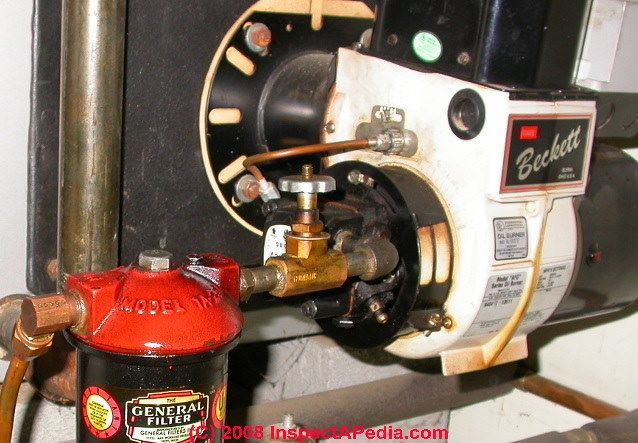
Our photo at below left shows an example of a Firematic™ safety valve right at the oil burner. Synonyms people use for this valve include OSV, fire safety valve, oil line valve, Fire-o-Matic valve, Fusible link valve, oil line shutoff valve, oil safety valve, and Fireomatic valve.
In particular, the OSV shown here is installed between the oil filter canister and the fuel unit intake port. That means that it would be impossible to service the oil filter without spilling heating oil unless the service technician finds another oil line shutoff valve somewhere between the oil tank and the inlet side of the oil filter.
With the shutoff valve between the filter canister and the oil burner (above right), changing the oil filter in the canister will require the service tech to go to the more distant oil tank to find and close a valve in that location (if one is even present).
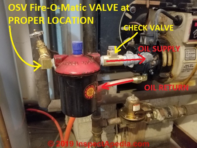
The technician moved the Fire-o-matic OSV to its proper location at the inlet side of the oil filter, and he also installed a Firomatic oil line check valve between the oil filter and the oil burner.
This is an important fire-safety detail as in event of a fire a closed valve on the return line (if it closes before the OSV on the supply line) could cause blowing seals on the oil pump or a blown oil line fitting, spewing fuel oil over the building fire.
In sum, the proper place for the fusible link oil valve (Fire-o-Matic Safety Valve™ for example) is on the oil supply line just before the inlet to the oil filter canister (red arrow, below left), not between the canister and the oil burner as shown at below right (orange arrow).
Below is another two-line oil system showing the OSV on the inlet side of the fuel filter canister just ahead of the oil burner and the oil return line exiting from the bottom of the fuel unit.
Regarding "the best location of an oil filter", NFPA 31 (2011): 7.5.8, for indoor tanks up to 330 gallons, requires that a thermally activated shutoff valve be placed inline as close as practical to the outlet from a tank and that a proper filter or screen be installed downstream and WITHIN SIX INCHES of the required thermally actuated valve. If it"s required in the code, it doesn"t have to "the best" - it just has to comply with the code.
Many oil heat technicians sensibly want to install a fusible-link oil supply line valve at the oil burner, not only because this makes servicing the oil burner easier but because it also recognizes that the most-likely location of a fire is at the oil burner rather than possibly at a more distant oil storage tank.
The photograph above shows the right location for this safety device: at the input end of the oil filter. This permits the service technician to conveniently turn off the oil supply inorder to change the oil filter cartridge.
The writers of NFPA 31 (2011) 7.5.8 as specified above were focused on safety including wanting to avoid oil spills from the tank, but they might also have recognizede that putting an oil filter at the oil tank protects the oil line (between tank and oil burner) from sludge-clogging.
(Jan 23, 2014) oilman said: Your info is wrong. The filter belongs on the tank so it also protects the oil line. If you must install at the burner, it must be piped at least 12" from the pump. Hence why they make 12" flexible oil lines.
Reply: We agree that there is an advantage to protecting the oil line. However some HVAC instructors (including mine) teach that if the filter is not installed by the burner it is too often forgotten at service time.
When the oil tank is a bit more remote - across the garage and buried by the homeowner"s stored surfboards and hiking boots and boxes of tax receipts, the service tech enjoys being able to find the oil burner. Having inspected several thousand heating systems, my [DF] experience is that most of the time the OSV and filter are installed where they are convenient for service - which is usually close to the burner, notwithstanding the very good reasons for locating a filter at the inlet end of the oil line.
Our OPINION [DF] is that if the technician installs an OSV at the oil burner (and ahead of a filter if one is installed there), s/he should install a second OSV on the same oil supply line at the outlet from the oil tank, particularly if the oil tank outlet piping exits at the tank bottom, and ahead of the oil filter (if that"s where it"s installed).
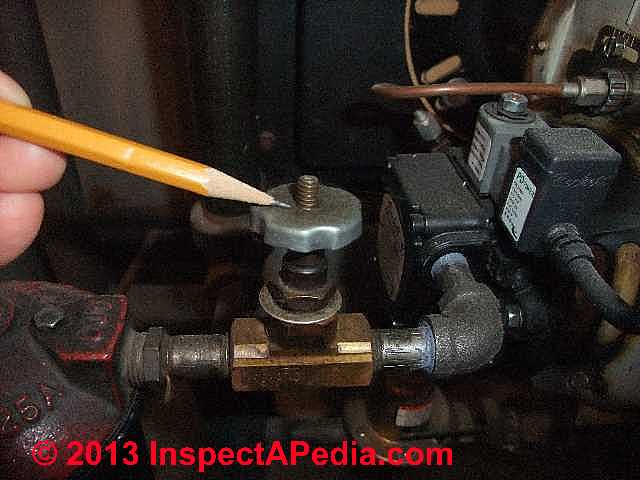
In our OSV photos below, the first photo (below left) shows the oil line safety valve in the OPEN position - oil will flow when the threaded portion of the valve shaft extends fully up through the rotatable knob pointed to by my pencil.[Click any image to see an enlarged version. Thanks to reader Bernie Daraz for pointing out the need for these two photos]
In our heating oil line valve photo at above right the valve has been manually CLOSED - no oil will flow. The threaded valve stem has disappeared down into the valve body and has shut off the valve and oil flow.
Watch out: if (for example in case of a fire) the fusible link inside of an OSV has melted permitting the spring to close the valve, then from outside the valve may look as if it is in the open position - the threaded stem will still be poking out - but the valve has snapped and closed internally. Most likely you"ll know this also because there will have been a fire or other horrible event that melted the OSV fusible link.
Watch out: A simple oil line shutoff valve may not be a fusible-link safety valve. The simple shutoff valve might be any plumbing valve that can manually stop oil flow in the line, but it is not a safety device.
Make sure you"ve installed a fusible-link safety valve at each location where it"s most needed - at each oil burner. Even when one of these valves is installed at the oil tank the proper place for this protection is on the fuel oil supply line
In the event of a fire, if the return oil line valve closes before the supply line oil valve your oil burner pump may burst the oil line or it may cause a fuel pump gasket or seal to fail, leading to uncontrolled oil flow and perhaps worse, spray heating oil everywhere, possibly feeding the building fire.
Thanks to Dave Ferris for this fire safety tip and thanks to reader Rick Johnston for adding clarification. (Note that not oil burners use both an oil supply and oil return line between the oil tank and oil burner.)
Suntec points out in their installation literature for fuel units (oil pumps for oil burners) that pressures over 10 psi on an oil inlet line (normally running at a vacuum) may damage the shaft seal on the pump - i.e., leak heating oil.
Watch Out: If the oil line fire safety valves are missing or are not at the right location, we recommend immediate installation of a Fire-o-matic™ type oil line safety
Recommended (red arrow, photo above left): an automatic oil line shutoff valve on the oil supply line right at each and every individualoil burner: (a type that will shut off oil supply to the heating equipment in the event of a fire, such as a Fire-o-Matic™ valve) is shown in our photo at left.
By every oil burner, we mean for example that if your heating system and also your hot water heater each has its own oil burner then each burner should have an oil safety valve. (As in our photo above left).
A common but poor practice is to install an oil valve just at the oil tank or perhaps installing a single oil safety valve at the oil burner for the heating boiler but omitting the oil safety valve for the oil fired water heater in the same building.
A second oil line shutoff valve on the oil supply line at the oil tank (photo above right) is ok as long as you have also provided the first oil safety valve at the oil burner(s).
Some service technicians install a second oil safety valve at the oil tank or at another remote location away from the oil burner, such as at the building wall where an outdoor oil tank line enters the building, or right at the oil tank (photo at above right - this oil tank valve is leaking).
This second valve is helpful if it becomes necessary to replace the oil line between oil tank and oil burner. Although our photo above shows a fusible link oil valve at the oil tank, the oil line shutoff valve at the oil tank or at a location remote from the oil burner or other more likely fire sources can be a normal plumbing stop valve.
However a common exception we see in the field is an OSV at the oil burner and a second OSV (or perhaps a simple shutoff valve, not thermally linked) at the oil tank end of the oil line.
Teflon tape at OSV threaded oil line or fuel unit connections: Webster"s instructions and some other manufacturers also specifically warn: Do Not Use Teflon Tape. Use of teflon tape voids all warranties. (Webster 2011)
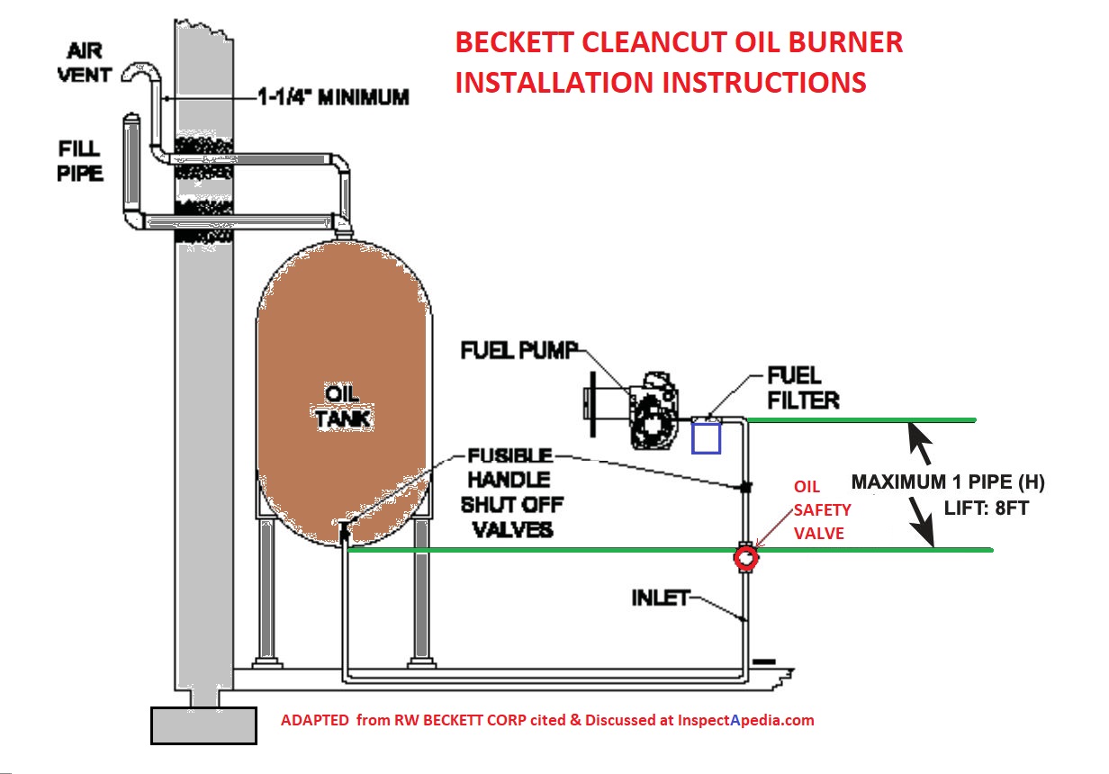
OSV too high: some instructions warn: Do not mount the OSV more than three feet above the burner fuel pump inlet, or more than three feet above the lowest point in the fuel line connecting the OSV to the burner fuel pump. In-line mounting with the burner fuel pump inlet is recommended.
Failure to observe the above caution may result in siphoning action in the event of failuire of the fuel line between the burner fuel pump and the OSV.
The concern is that should a fire occur in the building, and should an OSV on the oil return line close before the OSV on the supply line, the fuel unit may over-pressurize the oil lines, causing a burst oil line that then sprays high-pressure oil into the fire, increasing its size and spread-rate.
Use an oil line check valve instead. Or if the heating equipment manufacturer recommends against using a check valve in the oil piping system (Suntec prohibits, Webster recommends) then leave it out.
Our photo (left, red arrow) illustrates this hazard: you will see fusible link safety valves on both the oil feeder line (blue arrow, left side of photo before the oil filter canister) and the oil return line (red arrow, right side of the photograph).
Unlike a fusible link OSV that shuts in response to high temperature to provide fire protection at the oil burner, a vacuum operated OSV opens only in response to a "sustained vacuum" created at its outlet end when the oil burner"s fuel unit pump is drawing oil from the supply.
Vacuum-operated safety valves offer protection against oil line leaks and against overpressure conditions on the supply side of the fuel unit. They are not a fire-safety valve.
Protection against over-pressure from the supply piping prevents leaks at the fuel pump inlet or seals that might occur when the fuel pump is not operating but the supply piping is under pressure from the oil source.
If two oil lines are used to supply an oil burner, (a supply and a return) install an oil safety valve or OSV or fusible link oil line shutoff valve only on the oil supply line at the oil pump on the oil burner.Do NOT install an automatic oil line shutoff on the return oil line between the oil burner and the oil tank.
If a protection against oil back-flow at the return line is a concern, and if the manufacturer recommends it, use a check valve instead. Check valves like this one permit oil to flow just in one direction. They do not close down in event of a fire. Installed on the oil return line a check valve permits oil to flow from the oil pump in one direction only: back to the oil tank.
Typically the oil line de aerator device such as the Tigerloop is installed at the same location as the oil filter - just before oil enters the fuel unit (oil pump), as shown in our photograph at left, provided courtesy of reader E.I..
The Firomatic® oil line valve can be installed in ANY position - (vertical, horizontal, upside down) at least that"s what we were taught and what we have seen - the valve is spring loaded.
In a fire the fusible link, a lead core, melts at 165°F and a spring in the valve assembly snaps the valve shut to assure that the heating system does not feed oil to a building fire. It has to work in any orientation.
This list provides some of the companies produce fusible-link inline oil safety valves (OSVs). The footnote links point to the companies" contact information in our REFERENCES section, but generally you would purchase an OSV from your local heating equipment supplier or plumbing supplier.
AFL Industries, AFL OIL STOP VALVE PRODUCT BULLETIN [PDF] AFL Industries, 1101 West 13th St., Riviera Beach FL 33404 USA, Tel: 561-844-5200 includes OSV installation instructions for the contractor.
Bursey, Charles, "The Oil Safety Valve (Service)", Charles Bursey, Sr., Fuel Oil News, February 2006 (Still trying to get the full article - October 2008 - DF) Charles W. Bursey Sr. can be reached at F.W. Webb Co. www.fwwebb.com/
Cleanburn Energy CLEANBURN MULTI-OIL FURNACE OPERATORS MANUAL [PDF] (2009) Clean Burn Energy Systems, CLEAN BURN, INC. 34 Zimmerman Road Leola, PA 17540 U.S.A. includes Oil Safety Valve Installation Instructions
R.W. Beckett (U.S. & Canada) Firomatic Fire Safety Valves Beckett Corporation produces /distributes a wide range of oil burners & oil burner accessories * equipment including the oil safety valve (OSV) referred to as Firomatic® fusible fire safety valves, oil line check valves, and fusible link thermal switches
Beckett"s Firomatic® OSVs are provided in both 3/8" and 1/2" sizes and in flare and threaded designs. OSVs are provided designed for installation at the oil burner and in a different model at the oil storage tank.
Fusible fire safety valves are designed to reduce fire damage by shutting off the flow of oil from the oil tank in the event of a fire. These valves conform to UL/ULC 842 and are listed in the U.S. and Canada. They are required by code in residential oil heating installations in conformance with NFPA 31.
All[Firomatic® fire safety] valves are embossed with the direction of oil flow and include unique part number identification ring on each valve. The seal stem uses a double seal washer/o-ring system with high grade Viton® equivalent materials suitable for No. 2 fuel oil, kerosene, and jp to 205 biodiesel blend.
Oil under pressure or vacuum is supplied to the inlet of the PRV valve. Vacuum is required at the outlet of the PRV valve to open it and to allow oil to flow. When a burner starts, the pump will supply the vacuum necessary to open the valve. Any leak in the system which prevents vacuum from being exerted on the outlet port of teh valvewill prevent oil from flowing.
ISP Automation, Firomatic Globe Type Oil Line Valves & Lever Type Fusible Link Control Valves: ISP Automation, Inc., 1035 Old Georges Road, North Brunswick, NJ 08902, Phone: 866-383-3481, FAX 866-383-3482, Email: support@ispautomation.com http://www.ispautomation.com/
Webster "Service Technician"s Handbook, Webster Fuel Pumps & Valves" [handbook]. Webster Fuel Pumps & Valves, Capitol City Tool, Inc., http://www.websterfuelpumps.com/ , Division of Capital City Tool, Inc., Op. Cit.
Webster, OSV SERIES OIL SAFETY VALVES DIMENSIONS & SPECIFICATIONS [PDF] Fuel oil safety valves, Webster Fuel Pumps & Valves, web search 10/12/2011 original source http://www.websterfuelpumps.com/pdffiles/osv1.pdf
Webster, "Dimensions & Specifications, OSV Series Oil Safety Valves, OSVA 38, OSVA 50", Webster Fuel Pumps & Valves, (1980), Op. Cit. retrieved 2/24/2014, original source: http://www.websterfuelpumps.com/pdffiles/osv1.pdf
The current fusible link valve product properly named Firomatic is so widely also called "Firematic" and "Fireomatic" that we include those terms to assist readers in finding this information. Who manufactures the Firomatic fusible link valve? R.W. Beckett. Who manufactures vacuum-operated OSVs? Webster & Suntec (the PRV). We explain the differences among these products in this article series.
RW BECKETT RECALL for FIROMATIC 1/2" FEMALE PIPE THREAD FUSIBVLE SAFETY VALVE [PDF] P/N 12130 - the stem may not travel far enough to shut off the flow of fuel if exposed to trip point temperature. Posted until 4/1/2017, retrieved 2019/10/09 original source: https://static.globalindustrial.com/site/pdf/RW_Beckett_Firomatic_Female_Pipe_Thread_Recall.pdf
Excerpt: Recently, we became aware of a design deficiency in our ½” ‘Firomatic’ Fusible Safety Valve part number 12130. This bulletin covers ONLY the ½” FPT version p/n 12130, previous p/n B200F.
Under certain conditions, if the valve is exposed to temperatures exceeding the handle’s temperature rating and the valve ‘fires’ or actuates, the stem may not travel far enough to properly seat the valve and shut off the flow of fuel. This could result in a dangerous situation if there is a ruptured fuel line downstream of the valve. There have been no reports of this situation arising, but the potential for this issue to occur does exist. This does not affect the valve’s operation when used as a manual shut off valve.
The current design of the 12130 – ½” FPT valve and handle assembly was in production prior to R W Beckett’s acquisition of the Firomatic® product line. We have been unable to determine exact dates for any changes made to the design by previous manufacturers. Therefore this bulletin covers all Firomatic® ½” FPT valves, whether using our part number 12130 or the obsolete part number B200F, used by Highfield Manufacturing. Suspect valves can be identified by the name ‘Firomatic’ cast into the body of the valve. See illustration below.
A re-design of the 12130 valve will be available pending agency approvals and manufacturing process lead times. We are anticipating the re-designed valve to be available by January 1, 2017.
RW BECKETT RECALL for FIROMATIC 1/2" FEMALE PIPE THREAD FUSIBVLE SAFETY VALVE [PDF] P/N 12130 - OLDER COPY - the stem may not travel far enough to shut off the flow of fuel if exposed to trip point temperature. Posted until 4/1/2017, retrieved 2019/10/09 original source: https://static.globalindustrial.com/site/pdf/RW_Beckett_Firomatic_Female_Pipe_Thread_Recall.pdf
It might matter tremendously which way your OSV or oil safety valve is installed and in any event we ought to follow the manufacturer"s instructions including the flow arrow.
Here"s just one example. Some OSVs such as sold by Webster include a pressure-isolating feature that protects the fuel unit (the oil pump) from additional pressures that might come from the oil feed such as from an overhead oil feed line or even an elevated oil tank. Typically codes specify that the input pressure from the oil delivery piping ahead of the burner"s fuel unit not exceed 3 psi.
Those Webster OSVs include an internal valve that is designed to OPEN in RESPONSE to the FUEL UNIT OPERATION. So if the valve is installed backwards that feature will not work and the fuel unit may not pump oil properly to the burner nozzle.
Fusible Fire Safety Valves are designed to reduce fire damage by shutting off the flow of oil from the oil tank in the event of a fire. These valves conform to UL/ULC 842 and are listed in the US and Canada. They are required by code in residential oil heating installations in conformance with NFPA 31.
All valves are embossed with the direction of oil flow and include unique part number identification ring or each valve. The seal stem uses a double seal washer/ o-ring system with high grade Viton® equivalent materials suitable for No. 2 fuel oil, Kerosene and up to 20% Biodiesel blend.
Watch out: That"s because in the event of a fire a lead core in the valve is intended to melt to allow the valve to close - to stop feeding oil to a possible building fire. So if the valve is jammed it"s unsafe.
My concern is the stem does not go back into the valve or come out of it any further than it currently is no matter which direction I turn the valve or how many turns I make. Since the valve does not STOP turning in either direction, I"m concerned the valve is faulty.
If the stem pokes up out of the valve handle you"ve screwed the valve "down" and it is "open" to pass oil. Remember that these valves are threaded opposite of most others.
The knob on my OSV does not tighten up no matter how many times I turn it in either direction. The threaded stem in the center is protruding out about 2mm so I"m not sure if the valve is fully opened or closed. Is there a fix for this or do I need to replace the OSV?
If you have a fusible link valve that doesn"t seem to turn off you might try tapping the exposed end of the valve stem. I have found a stuck, or slow to close OSV on a few rare occasions. A gentle tap, not hard enough to damage threads, loosens it after which I open and close the valve a few times to convince myself it now moves freely. A burr on the brass interior or more likely internal sludge or debris could be the culprit.
Because at the oil burner the OSV is likely to be used at least once a year during service, that"s a good opportunity to discover if the valve is not closing fully.
In my opinion painting a fusible link is potentially unsafe - paint may interfere with mechanical operation of the valve. Most likely the manufacturer will agree, though they may not have imagined that event.
there must be an exception to the rule. my firematic valves open counter-clockwise and close clockwise and are definitely firematic valves because of their construction. they are just like the photos above but turn in the opposite direction you describe
I have a Themopride oil furnace that loses prime over night when the thermostat is lowed. It has a tigerloop installed. Why is there oil in the tigerloop if it loses prime?
Also, how do you recommend trouble shooting this? There are several valve one at each end of the supply line and one before the tigerloop that I could close for a few hours and see if it solves the problem (that would atleast narrow it down to a few fittings)
On a manual 1" fireomatic valve where the bonnett section joins the valve body, is that a brass on brass fit or is there suppose to be an o-ring or gasket? Does the OEM (Fireomatic) permitt valve disassembly for installation purposes? Thanks.
Mike I"ve installed these valves but have not tried disassembling one. If your unit is from Beckett, who currently provides the Fireomatic oil safety valve as well as the "New England Safety Switch" that uses a similar mechanism, then you might give them a call to ask.
Is there a inspection protocol for these valves like Morrison has on there fusible link valves (some quarterly inspections some yearly) and are they fine to use on gasoline lines I see only oil mentioned.
Watch out: do not use an oil line safety valve in ANY application other than those listed by UL and by the manufacturer - in this case, on heating oil supply lines.
Continue reading at OIL LINE SAFETY VALVE TURN DIRECTION to OPEN or SHUT or select a topic from the closely-related articles below, or see the complete ARTICLE INDEX.
OIL LINE SAFETY VALVES, OSVs at InspectApedia.com - online encyclopedia of building & environmental inspection, testing, diagnosis, repair, & problem prevention advice.
[1]AUDELS OIL BURNER GUIDE, INSTALLING, SERVICING, REPAIRING, [PDF online copy of this book] Frank D. Graham, Theo. Audel & Co., New York 1946, 1947, 1955 (out of print, copies occasionally available from antique book dealers and on EBay). Use THIS LINK to read a free online copy of this helpful classic textbook.
[2] Beckett Model SR Oil Burner Instruction Manual, R.W. Beckett Corporation, PO Box 1289, Elyria OH 44036 and R.W. Beckett Canada, Ltd., 430 Laird St., Guelph, Ontario, Canada N1G 3x7
[2a] "Beckett Cleancut Installation Information, Single Stage Fuel Unit PN 21844 & 2-Stage Fuel Unit PN 21941", R.W. Beckett Corporation, (2007) op .cit.,
[15] "Installation Information for Suntec A-2000, A-7000 Single Stage and B-8000 two stage fuel units"Suntec Industries, 60 Aberdeen Drive, Glasgow KY 42141, 270-651-7116 (1725 rpm black label, 3450 rpm white label)
[17] Newmac Furnaces & Boilers, "Installation, Operating, and Service Manual, Oil Fired Boiler Model NBR-2001 NBR 2002", (2007) Newmac Manufacturing, Inc., Debert Air Industrial Park, Lancaster Crescent, PO Box 9, Debert, Nova Scotia, BOM 1GO Canada, Tel: 902-662-3840, retrieved 2/23/2014
Thanks to Rick Johnston for pointing out that the more likely cause of a fire safety valve in the return oil line is a burst seal on the fuel unit 4/6/2009
Thanks to reader Bernie Daraz for suggesting the need for clear photographs illustrating the OSV or oil line safety valve in the open and closed positions. Personal correspondence 2/15/2013.
Thanks to reader T.R. for suggesting clarity on where oil safety valves should or should not be installed and for discussing the proper hook-up location for the Tigerloop and similar oil line prime protection & air removal devices. April 2011.
Thanks to reader Anonymous by request 2/23/2014, for requesting clarification of the safety hazards involved in placing an OSV on the return line of a two-pipe oil system.
TECHNICAL REFERENCE GUIDE to manufacturer"s model and serial number information for heating and cooling equipment, useful for determining the age of heating boilers, furnaces, water heaters is provided by Carson Dunlop Weldon & Associates
Surface-controlled subsurface safety valves (SCSSVs) are critical components of well completions, preventing uncontrolled flow in the case of catastrophic damage to wellhead equipment. Fail-safe closure must be certain to ensure proper security of the well. However, this is not the only function in which it must be reliable—the valve must remain open to produce the well. Schlumberger surface controlled subsurface safety valves exceed all ISO 10432 and API Spec 14A requirements for pressure integrity, leakage acceptance criteria, and slam closure.
Through decades of innovation and experience, Schlumberger safety valve flapper systems are proven robust and reliable. The multizone dynamic seal technology for hydraulic actuation of subsurface safety valves is a further improvement in reliability performance when compared with traditional seal systems in the industry.
The multizone seal technology is currently available in the GeoGuard high-performance deepwater safety valves, which is validated to API Spec 14A V1 and V1-H.
.png)
Pressure relief valve is related to Microchek.com. We offer competitive pricing and reliability because we are the manufacture. Parts are molded and assembled in the U.S. The Microchek system incorporates this cartridge and a wide selection of end pieces to accommodate most connection requirements. The Microchek valve is a cartridge check valve incorporating an innovative guided poppet design. Relief valves are used to hold a fluid circuit or reservoir at a positive or negative pressure. We can select valves that fall into a specific cracking pressure range if needed. The Microchek valve has a low pressure drop and can be specified with a wide variety of cracking pressures.
The Microchek valve is a cartridge check valve incorporating an innovative guided poppet design. Relief valves are used to hold a fluid circuit or reservoir at a positive or negative pressure. We want the opportunity to help you solve your flow control applications and we can build special configurations.
A shutoff valve shall be installed on the fuel-oil supply line at the entrance to the building. Inside or above-ground tanks are permitted to have valves installed at the tank. The valve shall be capable of stopping the flow of fuel oil to the building or to the
A relief valve shall be installed on the pump discharge line where a valve is located downstream of the pump and the pump is capable of exceeding the pressure limitations of the fuel oil system.
The relief valve shall discharge fuel oil when the pressure exceeds the limitations of the system. The discharge line shall connect to the fuel oil tank.

The primary purpose of a safety valve is to protect life, property and the environment. Safety valves are designed to open and release excess pressure from vessels or equipment and then close again.
The function of safety valves differs depending on the load or main type of the valve. The main types of safety valves are spring-loaded, weight-loaded and controlled safety valves.
Regardless of the type or load, safety valves are set to a specific set pressure at which the medium is discharged in a controlled manner, thus preventing overpressure of the equipment. In dependence of several parameters such as the contained medium, the set pressure is individual for each safety application.

A safety valve must always be sized and able to vent any source of steam so that the pressure within the protected apparatus cannot exceed the maximum allowable accumulated pressure (MAAP). This not only means that the valve has to be positioned correctly, but that it is also correctly set. The safety valve must then also be sized correctly, enabling it to pass the required amount of steam at the required pressure under all possible fault conditions.
Once the type of safety valve has been established, along with its set pressure and its position in the system, it is necessary to calculate the required discharge capacity of the valve. Once this is known, the required orifice area and nominal size can be determined using the manufacturer’s specifications.
In order to establish the maximum capacity required, the potential flow through all the relevant branches, upstream of the valve, need to be considered.
In applications where there is more than one possible flow path, the sizing of the safety valve becomes more complicated, as there may be a number of alternative methods of determining its size. Where more than one potential flow path exists, the following alternatives should be considered:
This choice is determined by the risk of two or more devices failing simultaneously. If there is the slightest chance that this may occur, the valve must be sized to allow the combined flows of the failed devices to be discharged. However, where the risk is negligible, cost advantages may dictate that the valve should only be sized on the highest fault flow. The choice of method ultimately lies with the company responsible for insuring the plant.
For example, consider the pressure vessel and automatic pump-trap (APT) system as shown in Figure 9.4.1. The unlikely situation is that both the APT and pressure reducing valve (PRV ‘A’) could fail simultaneously. The discharge capacity of safety valve ‘A’ would either be the fault load of the largest PRV, or alternatively, the combined fault load of both the APT and PRV ‘A’.
This document recommends that where multiple flow paths exist, any relevant safety valve should, at all times, be sized on the possibility that relevant upstream pressure control valves may fail simultaneously.
The supply pressure of this system (Figure 9.4.2) is limited by an upstream safety valve with a set pressure of 11.6 bar g. The fault flow through the PRV can be determined using the steam mass flow equation (Equation 3.21.2):
Once the fault load has been determined, it is usually sufficient to size the safety valve using the manufacturer’s capacity charts. A typical example of a capacity chart is shown in Figure 9.4.3. By knowing the required set pressure and discharge capacity, it is possible to select a suitable nominal size. In this example, the set pressure is 4 bar g and the fault flow is 953 kg/h. A DN32/50 safety valve is required with a capacity of 1 284 kg/h.
Coefficients of discharge are specific to any particular safety valve range and will be approved by the manufacturer. If the valve is independently approved, it is given a ‘certified coefficient of discharge’.
This figure is often derated by further multiplying it by a safety factor 0.9, to give a derated coefficient of discharge. Derated coefficient of discharge is termed Kdr= Kd x 0.9
Critical and sub-critical flow - the flow of gas or vapour through an orifice, such as the flow area of a safety valve, increases as the downstream pressure is decreased. This holds true until the critical pressure is reached, and critical flow is achieved. At this point, any further decrease in the downstream pressure will not result in any further increase in flow.
A relationship (called the critical pressure ratio) exists between the critical pressure and the actual relieving pressure, and, for gases flowing through safety valves, is shown by Equation 9.4.2.
Overpressure - Before sizing, the design overpressure of the valve must be established. It is not permitted to calculate the capacity of the valve at a lower overpressure than that at which the coefficient of discharge was established. It is however, permitted to use a higher overpressure (see Table 9.2.1, Module 9.2, for typical overpressure values). For DIN type full lift (Vollhub) valves, the design lift must be achieved at 5% overpressure, but for sizing purposes, an overpressure value of 10% may be used.
For liquid applications, the overpressure is 10% according to AD-Merkblatt A2, DIN 3320, TRD 421 and ASME, but for non-certified ASME valves, it is quite common for a figure of 25% to be used.
Two-phase flow - When sizing safety valves for boiling liquids (e.g. hot water) consideration must be given to vaporisation (flashing) during discharge. It is assumed that the medium is in liquid state when the safety valve is closed and that, when the safety valve opens, part of the liquid vaporises due to the drop in pressure through the safety valve. The resulting flow is referred to as two-phase flow.
The required flow area has to be calculated for the liquid and vapour components of the discharged fluid. The sum of these two areas is then used to select the appropriate orifice size from the chosen valve range. (see Example 9.4.3)
In order to ensure that the maximum allowable accumulation pressure of any system or apparatus protected by a safety valve is never exceeded, careful consideration of the safety valve’s position in the system has to be made. As there is such a wide range of applications, there is no absolute rule as to where the valve should be positioned and therefore, every application needs to be treated separately.
A common steam application for a safety valve is to protect process equipment supplied from a pressure reducing station. Two possible arrangements are shown in Figure 9.3.3.
The safety valve can be fitted within the pressure reducing station itself, that is, before the downstream stop valve, as in Figure 9.3.3 (a), or further downstream, nearer the apparatus as in Figure 9.3.3 (b). Fitting the safety valve before the downstream stop valve has the following advantages:
• The safety valve can be tested in-line by shutting down the downstream stop valve without the chance of downstream apparatus being over pressurised, should the safety valve fail under test.
• When setting the PRV under no-load conditions, the operation of the safety valve can be observed, as this condition is most likely to cause ‘simmer’. If this should occur, the PRV pressure can be adjusted to below the safety valve reseat pressure.
Indeed, a separate safety valve may have to be fitted on the inlet to each downstream piece of apparatus, when the PRV supplies several such pieces of apparatus.
• If supplying one piece of apparatus, which has a MAWP pressure less than the PRV supply pressure, the apparatus must be fitted with a safety valve, preferably close-coupled to its steam inlet connection.
• If a PRV is supplying more than one apparatus and the MAWP of any item is less than the PRV supply pressure, either the PRV station must be fitted with a safety valve set at the lowest possible MAWP of the connected apparatus, or each item of affected apparatus must be fitted with a safety valve.
• The safety valve must be located so that the pressure cannot accumulate in the apparatus viaanother route, for example, from a separate steam line or a bypass line.
It could be argued that every installation deserves special consideration when it comes to safety, but the following applications and situations are a little unusual and worth considering:
• Fire - Any pressure vessel should be protected from overpressure in the event of fire. Although a safety valve mounted for operational protection may also offer protection under fire conditions,such cases require special consideration, which is beyond the scope of this text.
• Exothermic applications - These must be fitted with a safety valve close-coupled to the apparatus steam inlet or the body direct. No alternative applies.
• Safety valves used as warning devices - Sometimes, safety valves are fitted to systems as warning devices. They are not required to relieve fault loads but to warn of pressures increasing above normal working pressures for operational reasons only. In these instances, safety valves are set at the warning pressure and only need to be of minimum size. If there is any danger of systems fitted with such a safety valve exceeding their maximum allowable working pressure, they must be protected by additional safety valves in the usual way.
In order to illustrate the importance of the positioning of a safety valve, consider an automatic pump trap (see Block 14) used to remove condensate from a heating vessel. The automatic pump trap (APT), incorporates a mechanical type pump, which uses the motive force of steam to pump the condensate through the return system. The position of the safety valve will depend on the MAWP of the APT and its required motive inlet pressure.
This arrangement is suitable if the pump-trap motive pressure is less than 1.6 bar g (safety valve set pressure of 2 bar g less 0.3 bar blowdown and a 0.1 bar shut-off margin). Since the MAWP of both the APT and the vessel are greater than the safety valve set pressure, a single safety valve would provide suitable protection for the system.
Here, two separate PRV stations are used each with its own safety valve. If the APT internals failed and steam at 4 bar g passed through the APT and into the vessel, safety valve ‘A’ would relieve this pressure and protect the vessel. Safety valve ‘B’ would not lift as the pressure in the APT is still acceptable and below its set pressure.
It should be noted that safety valve ‘A’ is positioned on the downstream side of the temperature control valve; this is done for both safety and operational reasons:
Operation - There is less chance of safety valve ‘A’ simmering during operation in this position,as the pressure is typically lower after the control valve than before it.
Also, note that if the MAWP of the pump-trap were greater than the pressure upstream of PRV ‘A’, it would be permissible to omit safety valve ‘B’ from the system, but safety valve ‘A’ must be sized to take into account the total fault flow through PRV ‘B’ as well as through PRV ‘A’.
A pharmaceutical factory has twelve jacketed pans on the same production floor, all rated with the same MAWP. Where would the safety valve be positioned?
One solution would be to install a safety valve on the inlet to each pan (Figure 9.3.6). In this instance, each safety valve would have to be sized to pass the entire load, in case the PRV failed open whilst the other eleven pans were shut down.
If additional apparatus with a lower MAWP than the pans (for example, a shell and tube heat exchanger) were to be included in the system, it would be necessary to fit an additional safety valve. This safety valve would be set to an appropriate lower set pressure and sized to pass the fault flow through the temperature control valve (see Figure 9.3.8).
During the forecast period, the global safety valve market size is estimated to reach USD 13.2 Billion by 2030 and is expected to exhibit a significant growth rate of 9.20% CAGR.
Safety Valves are precautionary valves that automatically actuate when the preset safety valve pressure and temperature are exceeded. These safety valves can be used to protect the critical equipment from damage by controlling excess pressure without any electrical support. For protecting equipment from unsafe pressure these mainly operate at a predetermined pressure. Additionally, these valves protect the employees around the plants and the environment around them. Safety valves are used in various applications like pharmaceutical, construction, oil & gas industries which foster the growth of the market.
During the lockdown, the global safety valve market is negatively impacted. Not only the safety valve market but the whole world was also affected drastically by this pandemic. To control the prevalence of the coronavirus, the government has imposed stringent regulations like lockdowns, maintaining social distance, covering the face with masks, manufacturing industries shut down, and transportation bans.
Even though at the primary stage of the pandemic, the safety valve market has fallen. Developing the innovations in the safety valve system and growing awareness regarding the benefits of the safety valve market by the key players are increasing the growth of this market.
Growing demand for safety valves in the oil & gas industry, the rise in nuclear energy generation, the growing importance of safety valves in industrial processes are the major driving factors of this market. The continuous need for safety valve replacement and the use of 3D printers in manufacturing lines are boosting the growth of the market. The safety valve market is highly dependent on investments in manufacturing facilities.
Some of the numerous factors that drive the safety valve market are rising demand for water & power, pollution control regulations, and rapid growth of process industries are supposed to escalate the growth of the safety valve industry during the assessment period. Growth in the construction of nuclear power plants is fueling the growth of the market. The increase of accidental incidences and soaring demand for safety valves in several industrial sectors are increasing the growth of the global market.
The constant growth of oil & gas exploration in few parts across the globe is restraining the market. The fabrication of safety valves are very expensive which is hindering the market growth
To increase the growth of the safety valve market industry integration of safety valves into the Internet of Things (IoT) environment is creating the opportunity. The innovations in the safety valve systems are anticipated to increase the strong growth of the market.
To provide a strategic profile of the prominent key players in the market, analyze their core competencies, forecast statistics, and draw a global safety valve market growth landscape.
The global safety valve market based on material is sub-segmented into steel, alloy, cast iron, cryogenic, and others. As the steel safety valves are durable and don’t leak in hot or cold temperatures, the steel segment is expected to dominate the global market.
It is segmented into less than 1”, 1” to 10”, and 11” to 20”, and 20” & above. Among these, during the review period, the 1” to 10” segment is projected to grow at the significant CAGR for the safety valves market for the benefits behind this size range like controlling the flow and pressure of liquids, gases, and slurries within different end-use industries.
The global safety valve market industry is divided into oil & gas, energy & power, food & beverage, chemicals, water & wastewater treatment, and others. In the global safety market, the oil & gas segment is expected to hold the largest share, because the oil & gas industries are the most significant revenue-generating industries which need almost all types of valves like gate, globe, ball, check and butterfly. Some of the products include a safety valve air compressor, safety valve boiler, and safety valve heater.
Asia-Pacific, Europe, North America, the Middle East & Africa, and South America are the main geographies included in this market. Due to the rapid urbanization and growing industrialization Asia-Pacific holds the largest safety valve market share.
The global safety valve market region-wise is divided into Asia-Pacific, Europe, North America, and the Middle East & Africa. Out of these regions, Asia-Pacific holds the largest market share for its growing infrastructural developments, rise of investments in various industries like oil & gas, construction industry, and drastic urbanization. Growing demand from mining, chemical, and municipal industries is expected to propel market growth in this region.
Safety valves are used in the application of the construction industry to control liquid flow in firefighting systems, water supply systems, and piping systems. The rising construction industry propels the market growth in this region. North America is accounting as the second-largest market for its growing investments in the construction industry.
Naples, Italy, Baker Hughes launched a new steam test facility in November 2018, ASME Section I safety valves that serve better to the European aftermarket with a rapid response for steam applications. The future development of the current aftermarket is launched as the new aftermarket plant which is expanded by the product scope and capacity of the plant. To fulfill the range of Masoneilan control valves and consolidated safety valves ranging up to 2000 psi test pressure.
In October 2018, Emerson Electric Co. to help the LNG marine transportation consumers developed low-pressure pilot operated pressure relief valves (POPRVs) by reducing their size which helps to reduce the investments by 25% and protects the end-users from overpressure by offering them extra profit margin.
In May 2019, the Mexican government announced that it is going to construct a new refinery set in the Tobasco coast, Mexico in June 2019. Hence safety valves are used in refineries to control the pressure of liquids and gases in plants.
This global safety valve market research includes the Market Overview, COVID-19 analysis, Market Dynamics, Study Objectives, Segment Overview, Regional Analysis, Competitive Landscape, Recent developments, Segmentation Table, and FAQs. The market scenario includes the safety valve market drivers, restraints, challenges, and opportunities. The safety valve forecast segments are material, size, end-use, and region.
.png)
As a design engineer responsible for developing and specifying boilers, dryers, furnaces, heaters, ovens and other industrial heating equipment, you face a daunting labyrinth of standards and industry regulations. Regulatory bodies sound a bit like alphabet soup, with acronyms like UL, FM, CSA, UR, AGA, ASME, ANSI, IRI, CE and NFPA tossed about. This article will help explain a common task for many thermal processing equipment specifiers: meeting the requirements of key codes — including Underwriters Laboratories (UL), Factory Mutual Insurers (FM) and the National Fire Protection Association (NFPA) — for safety valve equipment used in process heating applications.
Key to designing safety into your fuel train configurations are familiar technologies such as safety shutoff valves and vent valves as well as visual-indication mechanisms and proof-of-closure switches.
Your design skills come into play with how you take advantage of the wide range of products available. You can mix and match solenoid and safety shutoff valves — within designs from catalytic reactors to multi-zone furnaces — to create easily installed, cost-effective solutions that comply with all necessary standards. (See table.)
Make sure, however, that you start with a good grasp of valve element fundamentals. For example, examining a proof-of-closure (POC) switch underlines how reliably modern valves can ensure combustion safety. The POC unit provides an electrical contact interlocked with the controller safety circuit. In a typical design, the switch is located at the bottom of the valve, positioned to trace the stroke of the valve disc. When the disc seal reaches the fully closed position, it triggers the mechanism to push down on the contact, closing it and triggering the unit’s visual indicator to show open or closed status. As a result, the operator can act with full confidence in situations where it is critical that a safety valve be safely closed.
To provide ease of installation, many users prefer valves with modular capabilities. For example, to reduce mounting complexity, you can choose modular gas safety shut-off valves — combining a solenoid valve with an electrohydraulic motorized valve for a compact double-valve footprint, a slow-open feature and high flow rates. An accompanying actuator can provide on/off or high/low/off firing rates as well as visual indication and proof of closure for compliance with most industry standards.
Also, you may want to look for valves that include useful features such as pipe taps, which can facilitate accurate pressure readings and leakage testing.
Knowing your valve choices — and how they meet given codes and standards — can reduce the time required for design and production while facilitating compliance. This results in safer, more efficient and cost-effective heating process installations.


 8613371530291