
full opening safety valve factory
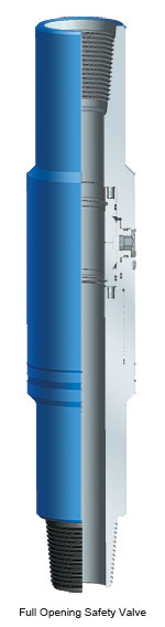
Full Opening Safety Valve (short for FOSV) is a ball type safety valve used to stop flow through the drill string when the drill string is being withdrawn from the well.
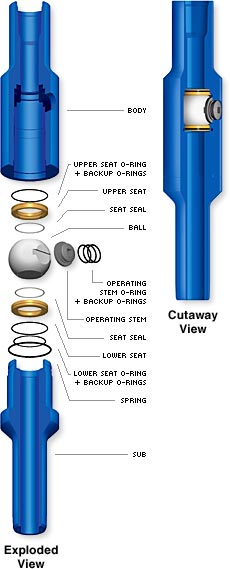
TIANHE FOSV is dual body full-opening safety valve, so it does not interfere with the running of tools such as core barrels or survey instruments. It is designed to be stabbed into the top joint of drill pipe or tubing string at the rig floor and closed quickly in case a well kicks.
The ball-type design permits the valve to be compact, easy to handle, and yet have great strength. Standard test pressure is 10,000PSI, but higher pressure ratings are available.
Two types of stabbing valves that must be prepared for well control are Full Opening Safety Valve (TIW valve) and Inside BOP valve (Gray Valve). We would like to describe what the differences between two valves are.
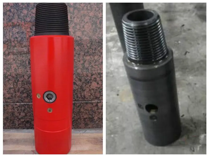
Full Opening Safety Valve or TIWvalve is a ball valve designed for high pressure condition and it can hold pressure from both directions. It is called “Full Opening” because when the ball valve is opened; the flow path through the valve has a smooth inside diameter. One thing that you need to remember is that the term “Full Opening” does not mean that the ID of the valve is the same of drill pipe ID. ID of the valve is typically smaller than the pipe in the hole.
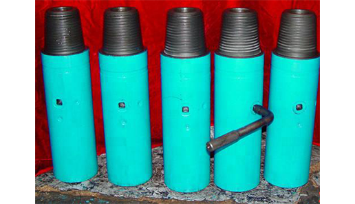
The valve should be always located on the rig floor and left in the open position. Additionally, you need to ensure that personnel on the rig have a right wrench to close the valve. The valve left in the open position is critical because the valve can stabbed quickly into drill string if the well flows through drill pipe.
For good drilling practices, you must have all size full opening safety valves which can be screwed into each size of drill pipe, drill collar, tubing, etc on the rig. When there is any string in the hole, the correct connection of the valve must be ready on the rig floor to stab in. Furthermore, it is a good practice to perform well control drill during tripping operation in order to ensure that the crew are familiar with the stabbing procedure.
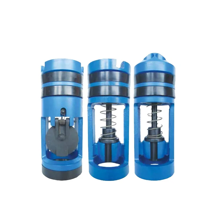
This valve is a non-return valve (check valve) allowing pumping through the valve into the drillstring but it prevents upward flow and the more widely used type is “dart-type”. The dart is used to hold the tool open therefore it is possible to stab the valve while the fluid is flowing through the drillpipe. With the IBOP valve installed in the drill string, it allows you to strip in hole without mud flowing through the drillsting. The IBOP valve should not be used for shut the well in while tripping.

Packard Safety Valves are designed to either stab into the drill pipe or tubing at the rig floor or are used as part of the drill string to shut off a well kick. Use of these valves in the drill string enhances rig safety.
The Packard two-piece safety valve offers the convenience of a two-piece body for easy maintenance. Its full bore also allows the unrestricted flow of drilling fluid; reducing wear on critical parts while providing unrestricted access for downhole tools.
Packard International"s Safety Valves are built with enough length on each end to allow fully recutting the connections in the event of damage to the threads or shoulders where sealing takes place.
High and low pressure sealing is assured by the Teflon and metal sealing system of the ball and seats. The ball and lower seat float while the upper seat is fixed in the body. This floating/fixed design aids in low pressure sealing and enables the operator to pressure balance the valve under full rated working pressure.

TIW is the original designer and manufacturer of ball type Safety and Kelly valves. Our strict adherence to API specifications as well as our own quality requirements ensures TIW valves are the highest quality valves in the market.
TIW Class I & Class II Kelly Valves may be utilized as a Drill Stem Safety Valve or as an Upper or Lower Kelly Cock and is designed to hold pressure from both directions.
TIW Kelly Valve Design and Quality System are certified by API.TIW Safety and Kelly Valves are also offered for H2S service, meeting all NACE standards. Standard Pressure rating is 10,000 PSI Test with higher pressure ratings available.

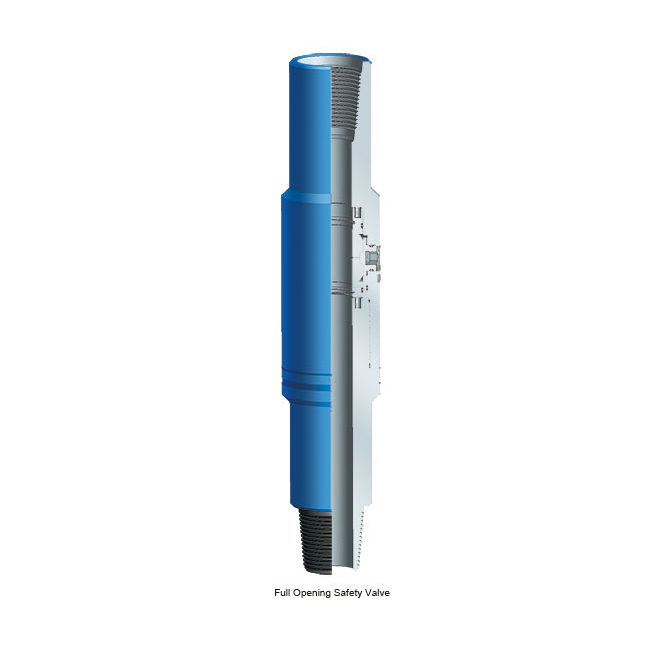
Full Opening Safety Valve (short for FOSV) is a ball type safety valve used to stop flow through the drill string when the drill string is being withdrawn from the well.
Our FOSV is dual body full-opening safety valve, so it does not interfere with the running of tools such as core barrels or survey instruments. It is designed to be stabbed into the top joint of drill pipe or tubing string at the rig floor and closed quickly in case a well kicks.
The ball-type design permits the valve to be compact, easy to handle, and yet have great strength. Standard test pressure is 10,000PSI, but higher pressure ratings are available.
Full Opening Safety Valve (short for FOSV) is designed to be stabbed into the top joint of drill pipe or tubing at the rig floor and closed quickly in case a well kicks. After weight material is added to the mud, the Kelly can be reconnected, the safety valve opened, and circulation initiated.
Like the Kelly valve, the Safety Valve is full opening. The ball-type design permits the valve to be compact, easy to handle, and yet have great strength. Available in 5000 PSI, 10000 psi and 15000 psi at your requeres.
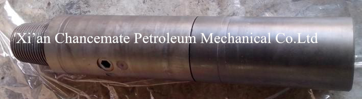
FULL OPENING SAFETY VALVE, OD: 3.1/2", MIN ID: 2-1/4", WORKING PRESSURE 5000 PSI, CONNECTION 3.1/2" IF , COMPLETE WITH WRENCH, WITHOUT HYDROGEN SULFIDE

Curtiss-Wright"s selection of Pressure Relief Valves comes from its outstanding product brands Farris and Target Rock. We endeavor to support the whole life cycle of a facility and continuously provide custom products and technologies. Boasting a reputation for producing high quality, durable products, our collection of Pressure Relief Valves is guaranteed to provide effective and reliable pressure relief.
While some basic components and activations in relieving pressure may differ between the specific types of relief valves, each aims to be 100% effective in keeping your equipment running safely. Our current range includes numerous valve types, from flanged to spring-loaded, threaded to wireless, pilot operated, and much more.
A pressure relief valve is a type of safety valve designed to control the pressure in a vessel. It protects the system and keeps the people operating the device safely in an overpressure event or equipment failure.
A pressure relief valve is designed to withstand a maximum allowable working pressure (MAWP). Once an overpressure event occurs in the system, the pressure relief valve detects pressure beyond its design"s specified capability. The pressure relief valve would then discharge the pressurized fluid or gas to flow from an auxiliary passage out of the system.
Below is an example of one of our pilot operated pressure relief valves in action; the cutaway demonstrates when high pressure is released from the system.
Air pressure relief valves can be applied to a variety of environments and equipment. Pressure relief valves are a safety valve used to keep equipment and the operators safe too. They"re instrumental in applications where proper pressure levels are vital for correct and safe operation. Such as oil and gas, power generation like central heating systems, and multi-phase applications in refining and chemical processing.
At Curtiss-Wright, we provide a range of different pressure relief valves based on two primary operations – spring-loaded and pilot operated. Spring-loaded valves can either be conventional spring-loaded or balanced spring-loaded.
Spring-loaded valves are programmed to open and close via a spring mechanism. They open when the pressure reaches an unacceptable level to release the material inside the vessel. It closes automatically when the pressure is released, and it returns to an average operating level. Spring-loaded safety valves rely on the closing force applied by a spring onto the main seating area. They can also be controlled in numerous ways, such as a remote, control panel, and computer program.
Pilot-operated relief valves operate by combining the primary relieving device (main valve) with self-actuated auxiliary pressure relief valves, also known as the pilot control. This pilot control dictates the opening and closing of the main valve and responds to system pressure. System pressure is fed from the inlet into and through the pilot control and ultimately into the main valve"s dome. In normal operating conditions, system pressure will prevent the main valve from opening.
The valves allow media to flow from an auxiliary passage and out of the system once absolute pressure is reached, whether it is a maximum or minimum level.
When the pressure is below the maximum amount, the pressure differential is slightly positive on the piston"s dome size, which keeps the main valve in the closed position. When system pressure rises and reaches the set point, the pilot will cut off flow to the dome, causing depressurization in the piston"s dome side. The pressure differential has reversed, and the piston will rise, opening the main valve, relieving pressure.
When the process pressure decreases to a specific pressure, the pilot closes, the dome is repressurized, and the main valve closes. The main difference between spring-loaded PRVs and pilot-operated is that a pilot-operated safety valve uses pressure to keep the valve closed.
Pilot-operated relief valves are controlled by hand and are typically opened often through a wheel or similar component. The user opens the valve when the gauge signifies that the system pressure is at an unsafe level; once the valve has opened and the pressure has been released, the operator can shut it by hand again.
Increasing pressure helps to maintain the pilot"s seal. Once the setpoint has been reached, the valve opens. This reduces leakage and fugitive emissions.
At set pressure the valve snaps to full lift. This can be quite violent on large pipes with significant pressure. The pressure has to drop below the set pressure in order for the piston to reseat.
At Curtiss-Wright we also provide solutions for pressure relief valve monitoring. Historically, pressure relief valves have been difficult or impossible to monitor. Our SmartPRV features a 2600 Series pressure relief valve accessorized with a wireless position monitor that alerts plant operators during an overpressure event, including the time and duration.
There are many causes of overpressure, but the most common ones are typically blocked discharge in the system, gas blowby, and fire. Even proper inspection and maintenance will not eliminate the occurrence of leakages. An air pressure relief valve is the only way to ensure a safe environment for the device, its surroundings, and operators.
A PRV and PSV are interchangeable, but there is a difference between the two valves. A pressure release valve gradually opens when experiencing pressure, whereas a pressure safety valve opens suddenly when the pressure hits a certain level of over pressurization. Safety valves can be used manually and are typically used for a permanent shutdown. Air pressure relief valves are used for operational requirements, and they gently release the pressure before it hits the maximum high-pressure point and circulates it back into the system.
Pressure relief valves should be subject to an annual test, one per year. The operator is responsible for carrying out the test, which should be done using an air compressor. It’s imperative to ensure pressure relief valves maintain their effectiveness over time and are checked for signs of corrosion and loss of functionality. Air pressure relief valves should also be checked before their installation, after each fire event, and regularly as decided by the operators.
Direct-acting solenoid valves have a direct connection with the opening and closing armature, whereas pilot-operated valves use of the process fluid to assist in piloting the operation of the valve.
A control valve works by varying the rate of fluid passing through the valve itself. As the valve stem moves, it alters the size of the passage and increases, decreases or holds steady the flow. The opening and closing of the valve is altered whenever the controlled process parameter does not reach the set point.
Control valves are usually at floor level or easily accessible via platforms. They are also located on the same equipment or pipeline as the measurement and downstream or flow measurements.
An industrial relief valve is designed to control or limit surges of pressure in a system, most often in fluid or compressed air system valves. It does so as a form of protection for the system and defending against instrument or equipment failure. They are usually present in clean water industries.
A PRV is often referred to as a pressure relief valve, which is also known as a PSV or pressure safety valve. They are used interchangeably throughout the industry depending on company standards.
The M&M International CANISTER GUARD® encapsulates its internal spring loading within the canister itself, which is a significant feature that cannot be overstated. During disassembly of one-piece valves made by other manufacturers, the internal spring must be compressed prior to removal of the locking mechanism. Considering the application, it is typical for mud, cement, debris, and/or corrosion to accumulate in this area. This makes it difficult or even impossible to compress the spring enough to remove the locking mechanism from valves of this kind, even when using the special tools required by the competitor manufacturer. These and other issues can make field dressing impractical and shop dressing a much longer and more expensive process than necessary. M&M International’s CANISTER GUARD® technology completely eliminates these issues, saving both time and money.
M&M International’s CANISTER GUARD® reduces the need for customer locations to keep large spare valve parts inventories on hand. In most cases, CANISTER GUARD® valves utilize identical parts within each size range. This low inventory ability allows a customer to operate with one spare canister and one or two spare operating stems in inventory, if necessary.
The primary purpose of a safety valve is to protect life, property and the environment. Safety valves are designed to open and release excess pressure from vessels or equipment and then close again.
The function of safety valves differs depending on the load or main type of the valve. The main types of safety valves are spring-loaded, weight-loaded and controlled safety valves.
Regardless of the type or load, safety valves are set to a specific set pressure at which the medium is discharged in a controlled manner, thus preventing overpressure of the equipment. In dependence of several parameters such as the contained medium, the set pressure is individual for each safety application.

The Pressure Safety Valve Inspection article provides you information about inspection of pressure safety valve and pressure safety valve test in manufacturing shop as well as in operational plants.
Your pressure safety valve is a direct spring-loaded pressure-relief valve that is opened by the static pressure upstream of the valve and characterized by rapid opening or pop action.
Your construction code for pressure safety valve is API Standard 526 and covers the minimum requirements for design, materials, fabrication, inspection, testing, and commissioning.
These are:API Recommended Practice 520 for Sizing and SelectionAPI Recommended practice 521 Guideline for Pressure Relieving and Depressing SystemsAPI Recommended Practice 527 Seat Tightness of Pressure Relief Valves
For example if there is pressure vessel need to be installed in the state of Minnesota then the pressure vessel nameplate shall be U stamped and pressure vessel safety valve shall be UV stamped.
National Board Inspection Code (NBIC) have own certification scheme for pressure safety valves and using NB symbol. The NBIC code book for this certification is NB 18.
There are some other standards and codes which are used in pressure safety valve such as:ASME PTC 25 for pressure relief devices which majorly is used for assessment of testing facility and apparatus for safety valvesBS EN ISO 4126-1, 4126-2 and 4126-3 which is construction standard similar to API STD 526.
This API RP 527 might be used in conjunction of API RP 576 as testing procedure for seat tightness testing of pressure safety valve for periodical servicing and inspection.
These are only important points or summery of points for pressure safety valve in-service inspection and should not be assumed as pressure safety valve inspection procedure.
Pressure safety valve inspection procedure is comprehensive document which need to cover inspection methods to be employed, equipment and material to be used, qualification of inspection personnel involved and the sequence of the inspection activities as minimum.
You may use following content as summery of points for Pressure Safety Valve Inspection in operational plantDetermination pressure safety valve inspection interval based API STD 510 and API RP 576 requirementsInspection of inlet and outlet piping after pressure safety valve removal for any foulingInspection of pressure safety valve charge and discharge nozzles for possible deposit and corrosion productsTaking care for proper handling of pressure safety valves from unit to the valve shop. The detail of handling and transportation instruction is provided in API RP 576.Controlling of seals for being intact when the valves arrived to the valve shop.Making as received POP test and recording the relieving pressure.
If the POP pressure is higher than the set pressure the test need to be repeated and if in the second effort it was near to the set pressure it is because of deposit.If in the second effort it was not opened near to the set pressure either it was set wrongly or it was changed during the operationIf the pressure safety valve was not opened in 150% of set pressure it should be considered as stuck shut.If the pressure safety valve was opened below the set pressure the spring is weakenedMaking external visual inspection on pressure safety valve after POP test. The test need contain following item as minimum;the flanges for pitting and roughness
Making body wall thickness measurementDismantling of pressure safety valve if the result of as received POP test was not satisfactoryMaking detail and comprehensive visual and dimensional inspection on the dismantled valve parts (after cleaning)Making special attention to the dismantled valves seating surfaces inspection e.g. disk and seat for roughness, wear and damage which might cause valve leakage in serviceReplacing the damaged parts in dismantled valves based manufacture recommendation and API RP 576 requirementsMaking precise setting of the pressure safety valve after reassembly based manufacture recommendation or NB-18 requirements
Making at least two POP test after setting and making sure the deviation from set pressure is not more than 2 psi for valves with set pressure equal or less than 70 psi or 3% for valves with set pressure higher than 70 psiMaking valve tightness test for leakage purpose after approval of the setting pressure and POP tests. The test method and acceptance criteria must be according to the API RP 576.The API RP 527 also can be used for pressure safety valve tightness test.Recording and maintaining the inspection and testing results.
Many electronic, pneumatic and hydraulic systems exist today to control fluid system variables, such as pressure, temperature and flow. Each of these systems requires a power source of some type, such as electricity or compressed air in order to operate. A pressure Relief Valve must be capable of operating at all times, especially during a period of power failure when system controls are nonfunctional. The sole source of power for the pressure Relief Valve, therefore, is the process fluid.
Once a condition occurs that causes the pressure in a system or vessel to increase to a dangerous level, the pressure Relief Valve may be the only device remaining to prevent a catastrophic failure. Since reliability is directly related to the complexity of the device, it is important that the design of the pressure Relief Valve be as simple as possible.
The pressure Relief Valve must open at a predetermined set pressure, flow a rated capacity at a specified overpressure, and close when the system pressure has returned to a safe level. Pressure Relief Valves must be designed with materials compatible with many process fluids from simple air and water to the most corrosive media. They must also be designed to operate in a consistently smooth and stable manner on a variety of fluids and fluid phases.
The basic spring loaded pressure Relief Valve has been developed to meet the need for a simple, reliable, system actuated device to provide overpressure protection.
The Valve consists of a Valve inlet or nozzle mounted on the pressurized system, a disc held against the nozzle to prevent flow under normal system operating conditions, a spring to hold the disc closed, and a body/Bonnet to contain the operating elements. The spring load is adjustable to vary the pressure at which the Valve will open.
When a pressure Relief Valve begins to lift, the spring force increases. Thus system pressure must increase if lift is to continue. For this reason pressure Relief Valves are allowed an overpressure allowance to reach full lift. This allowable overpressure is generally 10% for Valves on unfired systems. This margin is relatively small and some means must be provided to assist in the lift effort.
Most pressure Relief Valves, therefore, have a secondary control chamber or huddling chamber to enhance lift. As the disc begins to lift, fluid enters the control chamber exposing a larger area of the disc to system pressure.
This causes an incremental change in force which overcompensates for the increase in spring force and causes the Valve to open at a rapid rate. At the same time, the direction of the fluid flow is reversed and the momentum effect resulting from the change in flow direction further enhances lift. These effects combine to allow the Valve to achieve maximum lift and maximum flow within the allowable overpressure limits. Because of the larger disc area exposed to system pressure after the Valve achieves lift, the Valve will not close until system pressure has been reduced to some level below the set pressure. The design of the control chamber determines where the closing point will occur.
A safety Valve is a pressure Relief Valve actuated by inlet static pressure and characterized by rapid opening or pop action. (It is normally used for steam and air services.)
A low-lift safety Valve is a safety Valve in which the disc lifts automatically such that the actual discharge area is determined by the position of the disc.
A full-lift safety Valve is a safety Valve in which the disc lifts automatically such that the actual discharge area is not determined by the position of the disc.
A Relief Valve is a pressure relief device actuated by inlet static pressure having a gradual lift generally proportional to the increase in pressure over opening pressure. It may be provided with an enclosed spring housing suitable for closed discharge system application and is primarily used for liquid service.
A safety Relief Valve is a pressure Relief Valve characterized by rapid opening or pop action, or by opening in proportion to the increase in pressure over the opening pressure, depending on the application and may be used either for liquid or compressible fluid.
A conventional safety Relief Valve is a pressure Relief Valve which has its spring housing vented to the discharge side of the Valve. The operational characteristics (opening pressure, closing pressure, and relieving capacity) are directly affected by changes of the back pressure on the Valve.
A balanced safety Relief Valve is a pressure Relief Valve which incorporates means of minimizing the effect of back pressure on the operational characteristics (opening pressure, closing pressure, and relieving capacity).
A pilotoperated pressure Relief Valve is a pressure Relief Valve in which the major relieving device is combined with and is controlled by a self-actuated auxiliary pressure Relief Valve.
A poweractuated pressure Relief Valve is a pressure Relief Valve in which the major relieving device is combined with and controlled by a device requiring an external source of energy.
A temperature-actuated pressure Relief Valve is a pressure Relief Valve which may be actuated by external or internal temperature or by pressure on the inlet side.
A vacuum Relief Valve is a pressure relief device designed to admit fluid to prevent an excessive internal vacuum; it is designed to reclose and prevent further flow of fluid after normal conditions have been restored.
Many Codes and Standards are published throughout the world which address the design and application of pressure Relief Valves. The most widely used and recognized of these is the ASME Boiler and Pressure Vessel Code, commonly called the ASME Code.
is the gauge pressure at which the lift is sufficient to discharge the predetermined flowing capacity. It is equal to the set pressure plus opening pressure difference.
is the calculated mass flow from an orifice having a cross sectional area equal to the flow area of the safety Valve without regard to flow losses of the Valve.
the pressure at which a Valve is set on a test rig using a test fluid at ambient temperature. This test pressure includes corrections for service conditions e.g. backpressure or high temperatures.
is the value of increasing static inlet pressure of a pressure Relief Valve at which there is a measurable lift, or at which the discharge becomes continuous as determined by seeing, feeling or hearing.
Because cleanliness is essential to the satisfactory operation and tightness of a safety Valve, precautions should be taken during storage to keep out all foreign materials. Inlet and outlet protectors should remain in place until the Valve is ready to be installed in the system. Take care to keep the Valve inlet absolutely clean. It is recommended that the Valve be stored indoors in the original shipping container away from dirt and other forms of contamination.
Safety Valves must be handled carefully and never subjected to shocks. Rough handling may alter the pressure setting, deform Valve parts and adversely affect seat tightness and Valve performance.
When it is necessary to use a hoist, the chain or sling should be placed around the Valve body and Bonnet in a manner that will insure that the Valve is in a vertical position to facilitate installation.
Many Valves are damaged when first placed in service because of failure to clean the connection properly when installed. Before installation, flange faces or threaded connections on both the Valve inlet and the vessel and/or line on which the Valve is mounted must be thoroughly cleaned of all dirt and foreign material.
Because foreign materials that pass into and through safety Valves can damage the Valve, the systems on which the Valves are tested and finally installed must also be inspected and cleaned. New systems in particular are prone to contain foreign objects that inadvertently get trapped during construction and will destroy the seating surface when the Valve opens. The system should be thoroughly cleaned before the safety Valve is installed.
The gaskets used must be dimensionally correct for the specific flanges. The inside diameters must fully clear the safety Valve inlet and outlet openings so that the gasket does not restrict flow.
For flanged Valves, draw down all connection studs or bolts evenly to avoid possible distortion of the Valve body. For threaded Valves, do not apply a wrench to the Valve body. Use the hex flats provided on the inlet bushing.
Safety Valves are intended to open and close within a narrow pressure range. Valve installations require accurate design both as to inlet and discharge piping. Refer to International, National and Industry Standards for guidelines.
The Valve should be mounted vertically in an upright position either directly on a nozzle from the pressure vessel or on a short connection fitting that provides a direct, unobstructed flow between the vessel and the Valve. Installing a safety Valve in other than this recommended position will adversely affect its operation.
Discharge piping should be simple and direct. A "broken" connection near the Valve outlet is preferred wherever possible. All discharge piping should be run as direct as is practicable to the point of final release for disposal. The Valve must discharge to a safe disposal area. Discharge piping must be drained properly to prevent the accumulation of liquids on the downstream side of the safety Valve.
The weight of the discharge piping should be carried by a separate support and be properly braced to withstand reactive thrust forces when the Valve relieves. The Valve should also be supported to withstand any swaying or system vibrations.
If the Valve is discharging into a pressurized system be sure the Valve is a "balanced" design. Pressure on the discharge of an "unbalanced" design will adversely affect the Valve performance and set pressure.
The Bonnets of balanced bellows safety Valves must always be vented to ensure proper functioning of the Valve and to provide a telltale in the event of a bellows failure. Do not plug these open vents. When the fluid is flammable, toxic or corrosive, the Bonnet vent should be piped to a safe location.
It is important to remember that a pressure Relief Valve is a safety device employed to protect pressure vessels or systems from catastrophic failure. With this in mind, the application of pressure Relief Valves should be assigned only to fully trained personnel and be in strict compliance with rules provided by the governing codes and standards.


 8613371530291