
furnace safety valve free sample

A boiler valve kit is a must-have for any homeowner with a boiler system. This brass valve kit features a vent safety valve that helps to protect your home from dangerous gas build-up. The included instructions make installation easy, and the durable brass construction ensures lasting performance. Keep your family safe with this essential boiler valve kit.
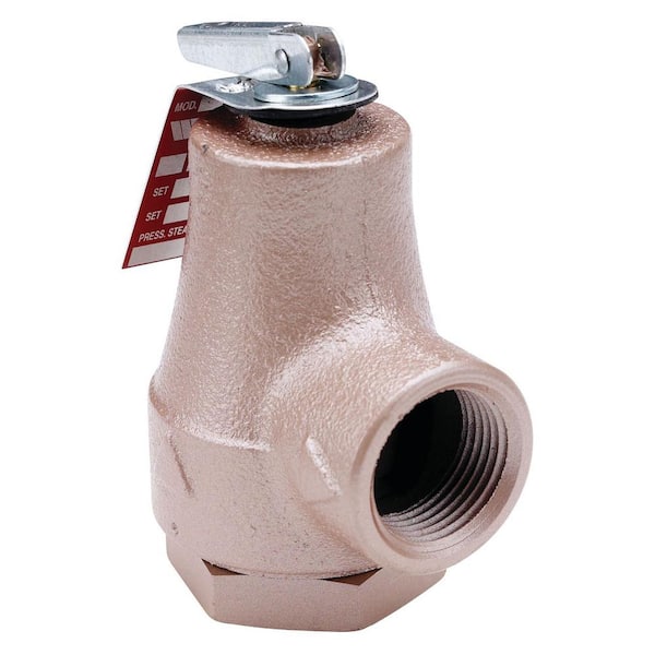
9. When the calibrated pressure is reached, the valve opens automatically and discharges the atmosphere to protect the whole system from safe caused by overpressure
10. This brass boiler valve kit is perfect for any steam-powered project. The kit includes a pressure gauge, safety valve, and two shut-off valves. The pressure gauge helps you monitor the pressure in your boiler, the safety valve keeps your boiler from exploding, and the shut-off valves let you turn off the steam supply without having to drain the boiler.
This brass boiler valve kit is perfect for any steam-related projects you may have. It includes a durable boiler and vent safety valve to keep your project safe and functional. The included instructions make it easy to install this kit in no time. This boiler valve kit is the perfect addition to your tool collection with its high-quality construction and affordable price. This brass boiler valve kit is ideal for any steam-based appliance. The kit includes a boiler valve, vent safety valve, and all the necessary fittings for a quick and easy installation. The included vent safety valve helps to ensure safe operation by releasing excess pressure in the event of a malfunction. This kit is ideal for use with any boiler, including cast iron, steel, or copper boilers.
Vent safety valves are required for all direct-fired appliances; this kit includes everything you need to install one. The boiler valve is brass and has a 1/2-inch pipe thread fitting that can be connected to the vent pipe. It also features an adjustable pressure relief valve with a gauge, protecting your home from high-pressure steam or air from the system. This kit comes with two elbows (1 in., two in.), four nipples (3/4 in., 1/8 in., 3/8 in.), three straight fittings (5/16 inches), and five pipe connectors (3 ways).
This boiler kit includes a brass pressure relief valve with an air vent, which is required by law. It also has a 1/2″ discharge elbow and two unions connecting the pipe inlet to your water heater. The safety valves are designed to prevent excess pressure from building up inside the tank, which can cause dangerous boil-overs or even potential explosions. This kit is excellent for homeowners with existing water heaters without this equipment installed.

As a design engineer responsible for developing and specifying boilers, dryers, furnaces, heaters, ovens and other industrial heating equipment, you face a daunting labyrinth of standards and industry regulations. Regulatory bodies sound a bit like alphabet soup, with acronyms like UL, FM, CSA, UR, AGA, ASME, ANSI, IRI, CE and NFPA tossed about. This article will help explain a common task for many thermal processing equipment specifiers: meeting the requirements of key codes — including Underwriters Laboratories (UL), Factory Mutual Insurers (FM) and the National Fire Protection Association (NFPA) — for safety valve equipment used in process heating applications.
Key to designing safety into your fuel train configurations are familiar technologies such as safety shutoff valves and vent valves as well as visual-indication mechanisms and proof-of-closure switches.
Your design skills come into play with how you take advantage of the wide range of products available. You can mix and match solenoid and safety shutoff valves — within designs from catalytic reactors to multi-zone furnaces — to create easily installed, cost-effective solutions that comply with all necessary standards. (See table.)
Make sure, however, that you start with a good grasp of valve element fundamentals. For example, examining a proof-of-closure (POC) switch underlines how reliably modern valves can ensure combustion safety. The POC unit provides an electrical contact interlocked with the controller safety circuit. In a typical design, the switch is located at the bottom of the valve, positioned to trace the stroke of the valve disc. When the disc seal reaches the fully closed position, it triggers the mechanism to push down on the contact, closing it and triggering the unit’s visual indicator to show open or closed status. As a result, the operator can act with full confidence in situations where it is critical that a safety valve be safely closed.
To provide ease of installation, many users prefer valves with modular capabilities. For example, to reduce mounting complexity, you can choose modular gas safety shut-off valves — combining a solenoid valve with an electrohydraulic motorized valve for a compact double-valve footprint, a slow-open feature and high flow rates. An accompanying actuator can provide on/off or high/low/off firing rates as well as visual indication and proof of closure for compliance with most industry standards.
Also, you may want to look for valves that include useful features such as pipe taps, which can facilitate accurate pressure readings and leakage testing.
Knowing your valve choices — and how they meet given codes and standards — can reduce the time required for design and production while facilitating compliance. This results in safer, more efficient and cost-effective heating process installations.

Boiler explosions have been responsible for widespread damage to companies throughout the years, and that’s why today’s boilers are equipped with safety valves and/or relief valves. Boiler safety valves are designed to prevent excess pressure, which is usually responsible for those devastating explosions. That said, to ensure that boiler safety valves are working properly and providing adequate protection, they must meet regulatory specifications and require ongoing maintenance and periodic testing. Without these precautions, malfunctioning safety valves may fail, resulting in potentially disastrous consequences.
Boiler safety valves are activated by upstream pressure. If the pressure exceeds a defined threshold, the valve activates and automatically releases pressure. Typically used for gas or vapor service, boiler safety valves pop fully open once a pressure threshold is reached and remain open until the boiler pressure reaches a pre-defined, safe lower pressure.
Boiler relief valves serve the same purpose – automatically lowering boiler pressure – but they function a bit differently than safety valves. A relief valve doesn’t open fully when pressure exceeds a defined threshold; instead, it opens gradually when the pressure threshold is exceeded and closes gradually until the lower, safe threshold is reached. Boiler relief valves are typically used for liquid service.
There are also devices known as “safety relief valves” which have the characteristics of both types discussed above. Safety relief valves can be used for either liquid or gas or vapor service.
Nameplates must be fastened securely and permanently to the safety valve and remain readable throughout the lifespan of the valve, so durability is key.
The National Board of Boiler and Pressure Vessel Inspectors offers guidance and recommendations on boiler and pressure vessel safety rules and regulations. However, most individual states set forth their own rules and regulations, and while they may be similar across states, it’s important to ensure that your boiler safety valves meet all state and local regulatory requirements.
The National Board published NB-131, Recommended Boiler and Pressure Vessel Safety Legislation, and NB-132, Recommended Administrative Boiler and Pressure Vessel Safety Rules and Regulationsin order to provide guidance and encourage the development of crucial safety laws in jurisdictions that currently have no laws in place for the “proper construction, installation, inspection, operation, maintenance, alterations, and repairs” necessary to protect workers and the public from dangerous boiler and pressure vessel explosions that may occur without these safeguards in place.
The American Society of Mechanical Engineers (ASME) governs the code that establishes guidelines and requirements for safety valves. Note that it’s up to plant personnel to familiarize themselves with the requirements and understand which parts of the code apply to specific parts of the plant’s steam systems.
High steam capacity requirements, physical or economic constraints may make the use of a single safety valve impossible. In these cases, using multiple safety valves on the same system is considered an acceptable practice, provided that proper sizing and installation requirements are met – including an appropriately sized vent pipe that accounts for the total steam venting capacity of all valves when open at the same time.
The lowest rating (MAWP or maximum allowable working pressure) should always be used among all safety devices within a system, including boilers, pressure vessels, and equipment piping systems, to determine the safety valve set pressure.
Avoid isolating safety valves from the system, such as by installing intervening shut-off valves located between the steam component or system and the inlet.
Contact the valve supplier immediately for any safety valve with a broken wire seal, as this indicates that the valve is unsafe for use. Safety valves are sealed and certified in order to prevent tampering that can prevent proper function.
Avoid attaching vent discharge piping directly to a safety valve, which may place unnecessary weight and additional stress on the valve, altering the set pressure.

The primary purpose of a safety valve is to protect life, property and the environment. Safety valves are designed to open and release excess pressure from vessels or equipment and then close again.
The function of safety valves differs depending on the load or main type of the valve. The main types of safety valves are spring-loaded, weight-loaded and controlled safety valves.
Regardless of the type or load, safety valves are set to a specific set pressure at which the medium is discharged in a controlled manner, thus preventing overpressure of the equipment. In dependence of several parameters such as the contained medium, the set pressure is individual for each safety application.
In order to ensure that the maximum allowable accumulation pressure of any system or apparatus protected by a safety valve is never exceeded, careful consideration of the safety valve’s position in the system has to be made. As there is such a wide range of applications, there is no absolute rule as to where the valve should be positioned and therefore, every application needs to be treated separately.
A common steam application for a safety valve is to protect process equipment supplied from a pressure reducing station. Two possible arrangements are shown in Figure 9.3.3.
The safety valve can be fitted within the pressure reducing station itself, that is, before the downstream stop valve, as in Figure 9.3.3 (a), or further downstream, nearer the apparatus as in Figure 9.3.3 (b). Fitting the safety valve before the downstream stop valve has the following advantages:
• The safety valve can be tested in-line by shutting down the downstream stop valve without the chance of downstream apparatus being over pressurised, should the safety valve fail under test.
• When setting the PRV under no-load conditions, the operation of the safety valve can be observed, as this condition is most likely to cause ‘simmer’. If this should occur, the PRV pressure can be adjusted to below the safety valve reseat pressure.
Indeed, a separate safety valve may have to be fitted on the inlet to each downstream piece of apparatus, when the PRV supplies several such pieces of apparatus.
• If supplying one piece of apparatus, which has a MAWP pressure less than the PRV supply pressure, the apparatus must be fitted with a safety valve, preferably close-coupled to its steam inlet connection.
• If a PRV is supplying more than one apparatus and the MAWP of any item is less than the PRV supply pressure, either the PRV station must be fitted with a safety valve set at the lowest possible MAWP of the connected apparatus, or each item of affected apparatus must be fitted with a safety valve.
• The safety valve must be located so that the pressure cannot accumulate in the apparatus viaanother route, for example, from a separate steam line or a bypass line.
It could be argued that every installation deserves special consideration when it comes to safety, but the following applications and situations are a little unusual and worth considering:
• Fire - Any pressure vessel should be protected from overpressure in the event of fire. Although a safety valve mounted for operational protection may also offer protection under fire conditions,such cases require special consideration, which is beyond the scope of this text.
• Exothermic applications - These must be fitted with a safety valve close-coupled to the apparatus steam inlet or the body direct. No alternative applies.
• Safety valves used as warning devices - Sometimes, safety valves are fitted to systems as warning devices. They are not required to relieve fault loads but to warn of pressures increasing above normal working pressures for operational reasons only. In these instances, safety valves are set at the warning pressure and only need to be of minimum size. If there is any danger of systems fitted with such a safety valve exceeding their maximum allowable working pressure, they must be protected by additional safety valves in the usual way.
In order to illustrate the importance of the positioning of a safety valve, consider an automatic pump trap (see Block 14) used to remove condensate from a heating vessel. The automatic pump trap (APT), incorporates a mechanical type pump, which uses the motive force of steam to pump the condensate through the return system. The position of the safety valve will depend on the MAWP of the APT and its required motive inlet pressure.
This arrangement is suitable if the pump-trap motive pressure is less than 1.6 bar g (safety valve set pressure of 2 bar g less 0.3 bar blowdown and a 0.1 bar shut-off margin). Since the MAWP of both the APT and the vessel are greater than the safety valve set pressure, a single safety valve would provide suitable protection for the system.
Here, two separate PRV stations are used each with its own safety valve. If the APT internals failed and steam at 4 bar g passed through the APT and into the vessel, safety valve ‘A’ would relieve this pressure and protect the vessel. Safety valve ‘B’ would not lift as the pressure in the APT is still acceptable and below its set pressure.
It should be noted that safety valve ‘A’ is positioned on the downstream side of the temperature control valve; this is done for both safety and operational reasons:
Operation - There is less chance of safety valve ‘A’ simmering during operation in this position,as the pressure is typically lower after the control valve than before it.
Also, note that if the MAWP of the pump-trap were greater than the pressure upstream of PRV ‘A’, it would be permissible to omit safety valve ‘B’ from the system, but safety valve ‘A’ must be sized to take into account the total fault flow through PRV ‘B’ as well as through PRV ‘A’.
A pharmaceutical factory has twelve jacketed pans on the same production floor, all rated with the same MAWP. Where would the safety valve be positioned?
One solution would be to install a safety valve on the inlet to each pan (Figure 9.3.6). In this instance, each safety valve would have to be sized to pass the entire load, in case the PRV failed open whilst the other eleven pans were shut down.
If additional apparatus with a lower MAWP than the pans (for example, a shell and tube heat exchanger) were to be included in the system, it would be necessary to fit an additional safety valve. This safety valve would be set to an appropriate lower set pressure and sized to pass the fault flow through the temperature control valve (see Figure 9.3.8).
Safety relief valves are relatively maintenance-free devices. Even so, it is recommended that a periodic inspection of these devices be done every six to 12 months.
A common maintenance error is to add a second relief valve onto the outlet of an existing relief valve that is leaking. This “stacking” of relief valves is not permissible by code.
By installing two relief valves in sequence, you add back pressure above the first relief valve piston, causing a change in the pressure setting. For example, the estimated relieving pressure of a valve stack could be:
As the relief flow then passes through the second valve, the stack also experiences a change in relieving capacity. If any of these conditions exist, the valve should be replaced.
The condition of the discharge piping should also be inspected. Valves should be piped to ensure that they do not collect dirt and debris. The vent pipes should be protected to prevent the entrance of rain water, which would inhibit valve operation.
Relief valves should be changed out after discharge to ensure safeguarding a system with a properly set relief valve. Most systems are subject to accumulations of piping debris (i.e., metal shavings and solder impurities) as the system is fitted for installation.
These impurities are generally blown into the relief valve seats at the time the valve is discharged. The impinged debris then inhibits the relief valve from reseating at its original set pressure.
Replacement intervals for valves that have not discharged may be dictated by city, state, or federal regulations. In addition, they may also be regulated by industry standards, company policies, insurance requirements, or unwritten, accepted standards of good practice.
In the case of city, state, or federal regulations and insurance regulations, there appear to be no written rules covering the replacement schedule. However, these agencies do govern by verbal requirements requesting that system operators-owners provide proof of the reliability of existing relief valves.
Industry standardsThe International Institute of Ammonia Refrigeration (IIAR), in its Bulletin 109, IIAR Minimum Safety Criteria for a Safe Ammonia Refrigeration System, recommends that the relief valve be replaced or inspected, cleaned, and tested every five years.
ANSI STD K61.1-1989, Safety Requirements for the Storage and Handling of Anhydrous Ammonia, is very specific in its requirements. Paragraph 6.8.15 states:
“No container pressure relief devices shall be used after the replacement date as specified by the manufacturer of the device. If no date is specified, a pressure relief valve shall be replaced no later than five years following the date of its manufacture.”
In industrial refrigeration, the current recommendation is to replace the relief valve on a five-year cycle. Be sure to check with other agencies to verify that a more stringent regulation is not applicable.
Provide a pressure vessel that will permit the relief valve to be set at least 25% above the maximum system pressure. However, the relief valve setting cannot exceed the maximum allowable working pressure as stamped on the vessel the relief valve is protecting.
 Use the proper size and length of discharge tube or pipe. Correct sizing is required to prevent back pressure from building up in the discharge line, preventing the relief valve from discharging at its rated capacity.
 The use of a three-way valve with two relief devices, which complies with the code requirements for vessels 10 cu ft or more in gross volume, is recommended for any installation containing a large quantity of expensive refrigerant.


 8613371530291