
gas oven safety valve testing factory

Our valves are subject to comprehensive testing to ensure that they can perform effectively in the relevant operating conditions. We recognise that lives can depend on the performance and reliability of our products and have invested heavily in the best testing facilities to give you greater peace of mind.
Our extensive facilities range from simple low-pressure testing for our more basic valves, to our new shock-resistant ballistic test bay. This bay enables us to replicate even the most demanding service conditions, with pressures of up to 60,000 psi for pipework and 21,500 psi for gas and hydro manifold valves.
All our testing bays include camera systems which enable us to record detailed footage of all tests, from a variety of angles simultaneously, to supplement the detailed findings of all testing activity.
Valve safety trains regulate the flow and pressure of fuel. In doing so, they keep the fuel delivery consistent with the requirements of the process. Importantly, they also keep gas out of the combustion chamber when equipment is cycled or shut off and ensure emergency shutdowns take place if a problem occurs.
Valve safety-train systems typically handle natural gas, but they can also transport propane, landfill, methane, sewer gas, oil, air, nitrogen or other types of bio-gas products. Regardless of the media handled, the maintenance, cleaning and repair of valve safety trains are mission-critical to employee safety and process control. When a valve safety train is not inspected and maintained on at least an annual basis, the results can be catastrophic. Unfortunately, action is often taken only after a tragic event.
Because of their complexity, employees tasked with servicing valve safety trains often misunderstand how they operate. To better appreciate what a valve safety train is and isn’t, a brief overview of their engineering is in order.
Valve safety trains are a coordinated group of mechanical and electrical devices to manage and monitor the fuel or other media. At the heart of every valve safety train is a safety shut-off valve (SSOV). The SSOV is the key safety component that ensures full flow isolation. Larger trains require dual SSOVs in series. Preceding the SSOV is various fuel-conditioning devices to clean the fuel and manage the pressure. After the SSOV, there are often flow-control valves and other devices to support the process needs.
Augmenting these devices are various manual shut-off valves (MSOV) that are used to isolate the process for maintenance purposes. Gas pressure switches are incorporated at key locations to monitor the fuel pressures and check against abnormal conditions. Additional ancillary devices such as pilot lines, vents, proving systems, instrumentation or flow meters may be incorporated to provide specific process-control needs.
Aside from the valve safety train, a burner management system (BMS) safety controller supervises and sequences light-offs and monitors safety. The BMS will direct fuel valves to close if a problem occurs. The safety premise of a BMS is to assume an unsafe condition exists unless each individual interlock has been proven and maintained in a safe condition. Only then will the BMS permit the combustion system to operate.
All components that make up a valve safety train must be listed or approved for their intended service by a nationally recognized testing agency, such as Underwriters Laboratories (UL), Factory Mutual (FM) or American Gas Association (AGA). Every component must be selected and properly rated not only for normal operating conditions but also for abnormal and failure modes.
Additionally, a valve safety train must be approved for use by an appropriate authority, which can vary depending on the locale and application of the larger system. On some applications, an expert from the underwriting authority or local government will inspect the valve safety train before it is put into service.
Preventing a valve safety-train incident requires diligence in both maintenance and inspection. Valve safety trains, like all industrial equipment, wear with use. For instance:Fuel flowing to a system can convey condensate, piping scale or other foreign materials that will either damage or block a safety valve from fully closing.
Gas pressure switches should be wired with a means that will prevent fuel from a failed switch flowing through a conduit or wiring to an electrical enclosure. Such a failure could cause an explosion if the fuel were to reach an arcing contact inside the electrical system.
If plug valves are installed, they must be properly serviced with the correct sealant. Plug valves that are low on sealant may leak externally or permit fuel to bypass a closed valve. Excessive use of sealant can build up in the piping, which may subsequently flow into other components.
Different components of the valve safety train may be on their own unique inspection frequencies set forth by the manufacturer or codes. It is strongly recommended, however, that the entire combustion system be inspected at least annually, both internally and externally while out of service, to ensure compliance.
Consult with NFPA 86 (Ovens and Furnaces) as a starting point. It provides guidelines to establish these measures, clearly stating, “The user has the responsibility for establishing a program of inspection, testing and maintenance with documentation performed at least annually.”
Does this mean that you are in the clear if the AHJ gives your valve safety train the OK? The short answer is “no.” Annual testing and preventive maintenance are typically requirements of insurance agencies, but other (often overlapping) codes and standards may need to be adhered to besides NFPA. These may include ANSI, ASME, NEC and the EPA. Oil-fired burners must comply with UL-296 Standard for Oil Burners, UL-726 Standard for Oil-Fired Boiler Assemblies or UL-2096 Standard for Commercial/Industrial Gas and/or Oil-Burning Assemblies with Emission Reduction Equipment.
A final word of caution: If you are in a location that does not mandate ASME CSD-1 (Controls & Safety Devices for Automatically Fired Boilers) or NFPA 85 compliance, the AHJ will rarely address fuel-system issues. Interlock and gas-train testing are typically assumed to be a responsibility of the owner. Therefore, an AHJ saying your boiler or dryer “passed” will bring no assurances that the valve safety train is compliant.
Given the potential danger of valve safety-train accidents, surprisingly few organizations have staff on-hand with the skills required to perform inspections or even basic maintenance, such as tuning a burner or changing a control valve. This absence of skilled staff comes despite statistics citing human error or lack of knowledge as the cause behind approximately 83% of boiler accidents, according to the National Board of Boiler and Pressure Vessel Inspectors.
Valve safety-train inspections should only be performed by highly trained, experienced flame-safeguard-control technicians. This person will inspect every part of the valve safety train, including interlocks, and replace necessary components. Many forward-thinking companies wisely contract a third party to inspect and maintain their burner equipment. An analysis of the plant’s code compliance or deficiencies will be conducted. The inspector will also review the plant’s maintenance practices regarding fuel delivery.
Upon conclusion of the inspection, a written report with data and photographic documentation will be presented to the plant manager. When done regularly, this written report allows the manager to compare and contrast the valve safety-train’s condition with that of previous inspections.
If annual inspections are not completed within the allotted time or if they are ignored, the plant owner may lose insurance coverage. Without insurance, a catastrophic explosion resulting from an unmaintained valve safety train represents a massive financial liability as well as a life-threatening hazard to employees.
Third-party contractors can provide both inspections and maintenance. If you are planning to do your own preventive maintenance, please begin by reviewing NFPA 54: The National Fuel Gas Code, which details safe gas-piping repair practices. Like NFPA 86, it is required reading. Valve safety-train manufacturers can provide training for more basic maintenance procedures.
Basic maintenance and housekeeping procedures that an in-house staff can perform include:SSOV leak testing –If a gas train has a double SSOV and vent line, you will need to perform a monthly test on each valve to ensure gas is not leaking into the combustion chamber or up the vent. At the very least, a leak will cost money in lost fuel and reduce the efficiency of the burner.
Flame color and shape –You can learn a lot from a burner flame. Check it daily. If it has been over a year since the last air-to-fuel ratio tuning, hire a technician to adjust it. Your flame should produce a clean burn with no soot or smoke and exhibit a uniform flame envelope. A natural gas flame that is blue or violet means you have a lean fire with excessive amounts of air. Unchecked, an excessively lean fire will create high levels of CO and white smoke. If your flame burns yellow, however, you have a fuel-rich fire. An orange flame or one that produces dark smoke is dangerous. Shut off the fuel immediately.
Vent-line inspection –Many vent lines are old and not maintained. When a venting device fails, it stays partially open and flows fuel to the vent line. Some failed devices will result in a loss of control, but not always. Regardless of the cause, raw gas pours out of the vent whenever equipment is pressurized. Failure is often uncovered only when someone reports the smell of gas. NFPA does state that all safety devices shall be tested on a regular basis. Some manufacturers offer “ventless” solutions as an option. This reduces the labor and material cost for installing proper venting.
Failure to inspect and maintain valve safety trains in proper working order will result in higher fuel costs, reduced heat transfer and the potential for a catastrophic explosion. Today’s valve safety trains are complex assemblies consisting of both electronic and mechanical components that need professionals to keep them in top shape.

As a design engineer responsible for developing and specifying boilers, dryers, furnaces, heaters, ovens and other industrial heating equipment, you face a daunting labyrinth of standards and industry regulations. Regulatory bodies sound a bit like alphabet soup, with acronyms like UL, FM, CSA, UR, AGA, ASME, ANSI, IRI, CE and NFPA tossed about. This article will help explain a common task for many thermal processing equipment specifiers: meeting the requirements of key codes — including Underwriters Laboratories (UL), Factory Mutual Insurers (FM) and the National Fire Protection Association (NFPA) — for safety valve equipment used in process heating applications.
Key to designing safety into your fuel train configurations are familiar technologies such as safety shutoff valves and vent valves as well as visual-indication mechanisms and proof-of-closure switches.
Your design skills come into play with how you take advantage of the wide range of products available. You can mix and match solenoid and safety shutoff valves — within designs from catalytic reactors to multi-zone furnaces — to create easily installed, cost-effective solutions that comply with all necessary standards. (See table.)
Make sure, however, that you start with a good grasp of valve element fundamentals. For example, examining a proof-of-closure (POC) switch underlines how reliably modern valves can ensure combustion safety. The POC unit provides an electrical contact interlocked with the controller safety circuit. In a typical design, the switch is located at the bottom of the valve, positioned to trace the stroke of the valve disc. When the disc seal reaches the fully closed position, it triggers the mechanism to push down on the contact, closing it and triggering the unit’s visual indicator to show open or closed status. As a result, the operator can act with full confidence in situations where it is critical that a safety valve be safely closed.
To provide ease of installation, many users prefer valves with modular capabilities. For example, to reduce mounting complexity, you can choose modular gas safety shut-off valves — combining a solenoid valve with an electrohydraulic motorized valve for a compact double-valve footprint, a slow-open feature and high flow rates. An accompanying actuator can provide on/off or high/low/off firing rates as well as visual indication and proof of closure for compliance with most industry standards.
Also, you may want to look for valves that include useful features such as pipe taps, which can facilitate accurate pressure readings and leakage testing.
Knowing your valve choices — and how they meet given codes and standards — can reduce the time required for design and production while facilitating compliance. This results in safer, more efficient and cost-effective heating process installations.

If your gas range is not working correctly, you should check the gas pressure regulator shut-off valve. The factory default setting for the gas pressure regulator is in the "ON" position but may have been turned to the "OFF" position during handling or transportation. When the shut-off valve is on the "OFF" position, gas will flow to the cooktop burners but will not provide a gas supply to the oven.
You can check if the shut-off valve if you can slide the range out from the cabinet. If you are unable to slide the range out, we recommend consultation with a local certified technician.
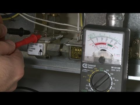
Verify the pressure regulator shut-off valve is in the open position. The pressure regulator is located at the back of the range. Make sure that the shut-off valve lever is in the "On" position (see illustration below).
NOTE: If the range is hard piped, you will not be able to slide it out from the cabinet if it connected with a flexible supply line, take care not to over-extend the supply line. The main gas valve will usually be at the end of a fixed pipe and connect to the pressure regulator with a flexible supply line. Take care not to kink or pinch this flexible pipe.

As a leading provider of flow equipment products, systems, and services to worldwide oil, gas, and process industries, we"re there where you are with innovative solutions and practical know-how.
Leveraging our global manufacturing, engineering, and sales and service network, we work with drilling contractors, oil and gas producers, pipeline operators, refiners, and other process owners to control, direct, adjust, process, and measure pressures and flows.
Through innovative organic development and strategic acquisition, we have built a broad portfolio of ASME and API valves that services the demands of global drilling, production, pipeline, storage, transmission, and critical service applications.

Valve test units for pressure testing any type of Safety Gate-, Globe-, Plug-, Ball-Check-, Slide- and Butterfly valve according to all international test standards.
D-Third Party Pressure Testing and Supply up to 45K PSI (Outdoor)Test bay is a part of 40ft container which capable to carry out hydrostatic test operation up to 45,000 psi remotely and totally separated (from the Operator Room) in safely manner.

Safety is of the utmost importance when dealing with pressure relief valves. The valve is designed to limit system pressure, and it is critical that they remain in working order to prevent an explosion. Explosions have caused far too much damage in companies over the years, and though pressurized tanks and vessels are equipped with pressure relief vales to enhance safety, they can fail and result in disaster.
That’s also why knowing the correct way to test the valves is important. Ongoing maintenance and periodic testing of pressurized tanks and vessels and their pressure relief valves keeps them in working order and keep employees and their work environments safe. Pressure relief valves must be in good condition in order to automatically lower tank and vessel pressure; working valves open slowly when the pressure gets high enough to exceed the pressure threshold and then closes slowly until the unit reaches the low, safe threshold. To ensure the pressure relief valve is in good working condition, employees must follow best practices for testing them including:
If you consider testing pressure relief valves a maintenance task, you’ll be more likely to carry out regular testing and ensure the safety of your organization and the longevity of your
It’s important to note, however, that the American Society of Mechanical Engineers (ASME) and National Board Inspection Code (NBIC), as well as state and local jurisdictions, may set requirements for testing frequency. Companies are responsible for checking with these organizations to become familiar with the testing requirements. Consider the following NBIC recommendations on the frequency for testing relief valves:
High-pressure steam boilers 400 psi and greater – pressure test to verify nameplate set pressure every three years or as determined by operating experience as verified by testing history
High-temperature hot water boilers (greater than 160 psi and/or 250 degrees Fahrenheit) – pressure test annually to verify nameplate set pressure. For safety reasons, removal and testing on a test bench is recommended
When testing the pressure relief valve, raise and lower the test lever several times. The lever will come away from the brass stem and allow hot water to come out of the end of the drainpipe. The water should flow through the pipe, and then you should turn down the pressure to stop the leak, replace the lever, and then increase the pressure.
One of the most common problems you can address with regular testing is the buildup of mineral salt, rust, and corrosion. When buildup occurs, the valve will become non-operational; the result can be an explosion. Regular testing helps you discover these issues sooner so you can combat them and keep your boiler and valve functioning properly. If no water flows through the pipe, or if there is a trickle instead of a rush of water, look for debris that is preventing the valve from seating properly. You may be able to operate the test lever a few times to correct the issue. You will need to replace the valve if this test fails.
When testing relief valves, keep in mind that they have two basic functions. First, they will pop off when the pressure exceeds its safety threshold. The valve will pop off and open to exhaust the excess pressure until the tank’s pressure decreases to reach the set minimum pressure. After this blowdown process occurs, the valve should reset and automatically close. One important testing safety measure is to use a pressure indicator with a full-scale range higher than the pop-off pressure.
Thus, you need to be aware of the pop-off pressure point of whatever tank or vessel you test. You always should remain within the pressure limits of the test stand and ensure the test stand is assembled properly and proof pressure tested. Then, take steps to ensure the escaping pressure from the valve is directed away from the operator and that everyone involved in the test uses safety shields and wears safety eye protection.
After discharge – Because pressure relief valves are designed to open automatically to relieve pressure in your system and then close, they may be able to open and close multiple times during normal operation and testing. However, when a valve opens, debris may get into the valve seat and prevent the valve from closing properly. After discharge, check the valve for leakage. If the leakage exceeds the original settings, you need to repair the valve.
According to local jurisdictional requirements – Regulations are in place for various locations and industries that stipulate how long valves may operate before needing to be repair or replaced. State inspectors may require valves to be disassembled, inspected, repaired, and tested every five years, for instance. If you have smaller valves and applications, you can test the valve by lifting the test lever. However, you should do this approximately once a year. It’s important to note that ASME UG136A Section 3 requires valves to have a minimum of 75% operating pressure versus the set pressure of the valve for hand lifting to be performed for these types of tests.
Depending on their service and application– The service and application of a valve affect its lifespan. Valves used for clean service like steam typically last at least 20 years if they are not operated too close to the set point and are part of a preventive maintenance program. Conversely, valves used for services such as acid service, those that are operated too close to the set point, and those exposed to dirt or debris need to be replaced more often.
Pressure relief valves serve a critical role in protecting organizations and employees from explosions. Knowing how and when to test and repair or replace them is essential.
VSI is your premier source for control valves, pressure relief valves, and safety relief valves. Our factory-certified experts are on-call 24/7 for repairs, testing, sizing & selection, replacement, and installation.
As your trusted source for factory-certified service solutions and consistent value and quality, VSI offers excellent customer service and world-class products and services. VSI has been focused on a legacy of quality and service since its inception in 1975 in Oklahoma City by founder Bill Campbell. Over the years, VSI has expanded its footprint to include four locations, offering service, repair, installation, and custom solutions across the United States. We offer excellent customer service, best-in-class products, and a wide variety of solutions for the process industry. VSI is the premier source for safety valves, pressure relief valves, control valves, and actuation products and services. Contact us to find out how we can help you.
Adapt almost any rotary actuator to a linear valve. Converting pneumatic actuation to electric helps increase operational efficiency and lower emissions.
VSI is a Consolidated™ Green Tag Center™ offering factory-certified repairs, installation, maintenance, and the full range of Consolidated pressure and safety relief valves. We have in-house certified technicians and product experts, and a large inventory to ensure fast delivery.
Our factory-certified and safety-trained, field service technicians are ready to be dispatched to your site. Capabilities include optimization, repair, and maintenance on pressure relief valves, safety valves, control valves, line valves, and actuation.
VSI has been helpful in many ways, from greasing valves, valve repair, valve replacement, and training our guys as well. We can’t say enough about quotes, labor support, material delivery time, and billing. Aaron has helped us out of several jams over the years and we appreciate it.
VSI has rebuilt our pressure relief valves here at [our processing plant] for several years now and I have always been very pleased with their service and quality of work. The work is always completed on time and we have had no reliability issues with the valves they’ve worked on. It’s always a pleasure working with VSI and I look forward to continuing the relationship.
The entire team at VSI has always been able to meet my needs and always exceeds my expectations. I have a great relationship with both the sales and service teams they are always ready to answer technical questions and provide excellent advice on ways to solve problems in the field and are always ready with solutions no matter how obscure or unusual the problem. VSI is more than ready and able to meet all my valve needs at any given moment.
Valve Sales Inc. provides outstanding service and support for all of our valve needs. Their dedication to quality and consistency allows our equipment to run more reliably and improves overall performance of our facility. Our goal is to provide consistent high performing products to our customers and VSI allows us to achieve this goal.
TULSA, OK – August 31, 2022 - Valve Sales Inc. (VSI), and Baker Hughes have partnered to distribute, service, and repair the complete line of Consolidated™ pressure relief valves. VSI’s service and… Read More

A: Maintenance should be performed on a regular basis. An initial inspection interval of no longer than 12 months is recommended. The user must establish an appropriate inspection interval depending on the service conditions, the condition of the valve and the level of performance desired.
The ASME Boiler and Pressure Vessel Code does not require nor address testing installed valves. The only thing the code states are design and installation requirements, such as some valves must have a lifting lever. For instance for Section VIII:
“Each pressure relief valve on air, water over 140° F, or steam service shall have a substantial lifting device which when activated will release the seating force on the disk when the pressure relief valve is subjected to a pressure of at least 75% of the set pressure of the valve.”
A: This drain hole is required on some models by the ASME Boiler and Pressure Vessel Code. It is intended to prevent any condensate from accumulating in the body that may freeze or corrode internal valve parts and prevent the valve from opening. The drain hole should be piped away to safely dispose of any discharge or condensate.
A: This is often a confusing topic. The correct installation often looks backwards from what appears to be correct. A paper instruction tag illustrating the proper connection is attached to each valve. Vacuum valves should have the NPT threads that are cast integral to the body attached to the vacuum source. See the assembly drawing for additional clarification.
A: Typically, the valve should be nameplate set to open at the MAWP (Maximum Allowable Working Pressure) of the vessel the valve is intended to protect. There is a tolerance to actual set pressure, which means a valve set at 100 psig nameplate may open slightly above or below 100 psig. Consult the current ASME Boiler and Pressure Vessel Code for tolerance classes and special situations when the set pressure may be different than the MAWP.
A: It is normal for spring-operated safety valves to exhibit leakage or simmer/warn, as the system operating pressure approaches the nameplate set pressure, typically in the 80%-90% range of nameplate set pressure. The ASME Boiler and Pressure Vessel Code does not require a specific seat tightness requirement. A certain level of leakage is allowed per manufacturers’ literature and API-527 Seat Tightness Performance Standards, both of which can be found in the Technical Reference Catalog and in the Data Supplement, summarized as follows:
API-527 Standard Seat Tightness Performance: A Functional Test Report (FTR) is automatically provided for valves ordered to API-527. See API 527 for complete details.
A: Maintain a minimum operating gap of 10% between the system operating pressure and the safety valve’s nameplate set pressure. Since direct spring-operated safety valves may “simmer” or “warn” at 90% of the nameplate set pressure, and since the factory standard leak test is performed at 80% of nameplate set pressure, better seat tightness performance can be expected with an operating gap of 20%.
Variance of set pressure is allowed, i.e., a Section VIII air valve with a nameplate of 100 psig set pressure may open from 97 psig to 103 psig, but will be factory set around 102 psig.
Gage issues may lead to incorrect reporting of set pressure. Ensure the gage is within calibration and is accurate for the pressure being measured. Rapid increases in system pressure (more than 2 psig/second, water hammer, reciprocating pumps) can make the valve appear to be opening early because the gage cannot accurately report the pressure to which the valve is exposed.
A: Yes. Section I valves have more stringent setting blowdown requirements and may be used in Section VIII steam applications since they meet all the requirements as specified in Section VIII UG-125(a) “Pressure Relief Devices,” which states pressure relief devices must be “in accordance with the requirements of UG-125 through UG-137.” In addition, UG-125(b) actually specifies that even unfired steam boilers MUST use a Section I pressure relief device.
A: Section VIII UG-136(a)(3) states, “Each pressure relief valve on air, water over 140° F (60° C), or steam service shall have a substantial lifting device which when activated will release the seating force on the disk when the pressure relief valve is subjected to a pressure of at least 75% of the set pressure of the valve.”
The user has a documented procedure and an associated implementation program for the periodic removal of the pressure relief valves for inspection and testing, and repair as necessary.
A: Back pressure reduces set pressure on a one-to-one basis, i.e., a valve set at 100 psig subjected to a backpressure at the outlet of 10 psig will not actuate until system pressure reaches 110 psig. Back pressure drastically reduces capacity; typically backpressure of 10% of set pressure will decrease capacity by 50%. Specific capacity reduction should be determined by the user on a case-by-case basis by flow testing. Back pressure in excess of 10% of set pressure is not recommended.
A: The ASME Boiler and Pressure Vessel Code does not have blowdown requirements for Section VIII (or non-code) valves. Blowdown may vary from less than 2% to more than 50%, depending on many factors including: valve design, dimensional tolerance variation, where the set pressure falls in the set pressure range of a spring, spring rate/force ratio, warn ring/guide settings, etc. Typical blowdown for most valves is 15% to 30%, but cannot be guaranteed. VM
Jim Knox is president, Allied Valve, Inc. (www.alliedvalve.com), a valve repair service company and supplier of Tyco Kunkle and Dresser Consolidated safety valves in the Midwest. Reach him at knoxj@alliedvalveinc.com.
In his presentation at VMA’s 2017 Technical Seminar, Kurt Larson, a process control engineer for Air Products, spoke about the inherent danger of the oxygen production business and how it is particularly important for end users and valve manufacturers to work closely together.

The control valve is a critical part of the control loop. The control valve manipulates a flowing fluid, such as gas, steam, water, or chemical compounds to compensate for the load disturbance and keeps the regulated process variable as close as possible to the desired set point.


 8613371530291