
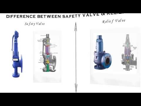
give the difference between safety valve and relief valve supplier

As you already know, there are a multitude of pressure relief valves out there. In the industry, we tend to use terms like safety valve and relief valve interchangeably. And for the most part, this makes sense. Most pressure relief valves are designed to do the same thing — release pressure in a system.
But is there a difference between some of these commonly used terms, and if so, what does it mean for you? Here’s a quick breakdown of two popular terms: safety valve vs. relief valve.
While both terms refer to valves used to release pressure from a pressurized system, their technical definitions are a bit different. In general, the term relief valve refers to a valve within a pressurized system that is used to control pressure for the optimal functionality of the system. Relief valves are designed to help your facility avoid system failures, and protect equipment from overpressurized conditions.
The term safety valve, on the other hand, refers to pressure valves that are designed to protect people, property, and processes. In other words, the term safety valve refers to a failsafe, last resort valve that will release pressure to prevent a catastrophe, usually in the event that all other relief valves have failed to adequately control pressure within a system.
The general purpose of both safety valves and relief valves are the same. Both are pressure relief valves, and they are designed to let off pressure in any situation where a system becomes overpressurized. That said, relief valves and safety valves do function slightly differently:
Relief Valves are designed to control pressure in a system, most often in fluid or compressed air systems. These valves open in proportion to the increase in system pressure. This means they don’t fly all the way open when the system is slightly overpressure. Instead, they open gradually, allowing the system to return to the preset pressure level. When that level is reached, the valve shuts again.
Safety Valves are used for one reason — safety. Instead of controlling the pressure in a system, they’re designed to immediately release pressure in the event of an emergency or system failure. Unlike relief valves, safety valves open immediately and completely to avoid a disaster, rather than to control the pressure of a system.
While both safety valves and relief valves work to release excess pressure, the way they go about it is a little different. Check out this table, courtesy of Difference Between, for a little more information about the differences between the two valves:

Industrial equipment often uses either safety or relief valves to prevent damaging pressure levels from building up. Though they perform similar functions, there are some critical differences between safety and relief valves. Understanding these two valves’ differences is essential for proper pressure system operation. So here we discuss the pressure safety valve vs pressure relief valve.
A pressure relief valve is a device that releases pressure from a system. The relief valve is generally immune to the effects of back pressure and must be periodically stripped down. Pressure relief valves are one the essential parts of a pressure system to prevent system failures. They are set to open at a predetermined pressure level. Each pressure system has a setpoint that is a predetermined limit. The setpoint determines when the valve will open and prevents overpressure.
Pressure relief valves are typically used in gas or liquid systems where there is a need to prevent excessive pressure from building up. When the pressure in the system reaches a certain level, the valve will open and release the pressure. Pressure relief valves are an essential safety feature in many designs and can help to prevent damage to the system or components.
PRVs are generally considered to be safe and reliable devices. However, before installing a PRV in a system, some potential disadvantages should be considered. Here are five pros and cons of pressure relief valves:
Pros: Pressure relief valves are anessential safety feature in many systems. They protect against over-pressurization by relieving excess pressure from the system. This can help to prevent severe damage or even explosions.
Pressure relief valves can help to improve the efficiency of a system. The system can operate at lower overall pressure by relieving excess pressure and saving energy.
Pressure relief valves can be used as a safety device in systems that are susceptible to overpressurization. By relieving pressure before it builds up to a dangerous level, they can help to prevent accidents and injuries.
Cons: Pressure relief valves can be a potential source of leaks. If not properly maintained, the valve may not seat properly and can allow fluids or gasses to escape.
Pressure relief valves can sometimes cause problems if they do not open or close properly. This can lead to process disruptions and may cause safety issues.
A pressure safety valve is a device used to release pressure from a system that has exceeded its design limit. This safety valve is a fail-safe device. This type of valve is typically used in systems that contain fluids or gasses under high pressure. Pressure safety valves are designed to open and release pressure when the system has exceeded its maximum pressure limit. This helps to prevent the system from rupturing or exploding.
Pressure safety valves are an essential part of many different types of systems and can help keep both people and property safe. If anyone is ever in a situation where they need to release pressure from a system, it is essential to know how to use a pressure safety valve correctly.
A pressure safety valve (PSV) is a type used to relieve a system’s pressure. PSVs are commonly used in chemical and process industries, as well as in some kinds of pressure vessels. There are both advantages and disadvantages to using a PSV. Some of the pros of using a PSV include: PSVs can help to prevent overpressurization, which can be dangerous.
A safety valve is a pressure relief device used to prevent the over-pressurization of a system. On the other hand, a relief valve is a device used to relieve pressure from a system that is already overpressurized. Function Of Pressure Relief Valve Vs Safety Valve
The function of a pressure relief valve is to protect a system or component from excess pressure. A safety valve, on the other hand, is designed to protect from overpressurization. Both types of valves are used in various industries, but each has unique benefits and drawbacks.
Pressure relief valves are typically used in systems where a small amount of overpressure can cause damage. On the other hand, safety valves are designed for systems where overpressurization could be catastrophic. Both valves have advantages and disadvantages, so choosing the right type of valve for the specific application is essential.
Relief valves are usually set to open at a specific pressure and will close once the pressure has been relieved. Safety valves are similar in that they are also used to protect equipment from excessive pressure. However, safety valves are designed to stay open until they are manually closed. This is because safety valves are typically used in applications where it is not safe to have a closed valve, such as in a gas line. Operation Of Safety Relief Valve Vs Pressure Relief Valve
Two types of valves are commonly used in industrial settings: relief valves and safety valves. Both of these valves serve essential functions, but they operate in different ways.
Relief valves are designed to relieve pressure build-up in a system. They open when the system pressure reaches a certain point, which allows excess pressure to be released. On the other hand, safety valves are designed to prevent accidents by preventing system pressure from getting too high. They open when the system pressure reaches a certain point, which allows excess pressure to be released before an accident can occur.
So, which valve is better? That depends on the situation. A relief valve is the better option to protect the system from pressure build-up. If anyone need to protect the system from accidents, then a safety valve is the better option Setpoint Of Pressure Relief Valve Vs Safety Relief Valve
The relief valve is made to open when it reaches a specific pressure, commonly described as a “setpoint”. Setpoints shouldn’t be misinterpreted as the pressure set. A setpoint on a relief valve is set to the lowest possible pressure rating, which means it is set to the lowest system pressure before an overpressure situation is observed. The valve will open as the pressure increases to a point higher than the setpoint. The setting point is determined as pounds per square inch (PSIG) and should be within the maximum allowed operating pressure (MAWP) limits. In safety valves, the setpoint is typically placed at about 3 percent over the working pressure level, whereas relief valves are determined at 10 percent.
No, the safety valve and relief valve can not be used interchangeably. Though both valves are seal butterfly valve and used for safety purposes, they serve different functions. A safety valve relieves excess pressure that builds up in a system, while a relief valve regulates the pressure in a system.
Knowing the difference between these two types of valves is essential, as using the wrong valve for the intended purpose can potentially be dangerous. If unsure which type of valve to use, it is always best to consult with a professional.
A few key points help us understand the safety valve vs pressure relief valve. Safety valves are designed to relieve pressure in a system when it gets too high, while relief valves are designed to relieve pressure when it gets too low. Safety valves are usually set to open at a specific pressure, while relief valves are generally open at a particular vacuum. Safety valves are typically intended for one-time use, while relief valves can be used multiple times. Choose the trusted valve manufactureraccording to the specific business needs.
This website is using a security service to protect itself from online attacks. The action you just performed triggered the security solution. There are several actions that could trigger this block including submitting a certain word or phrase, a SQL command or malformed data.

Whenever we talk about the pressure in the process industries we come across two types of safety equipments and that is the safety v/v and the relief v/v.
Most of us think that both are same thing but that’s not the case. Though their functions are same yet there are certain differences among them. Both of them are used in the industry to prevent the accumulation of excess pressure, but there are operational differences between them.
Relief valves which are also known as Pressure relief valves are one of the protective devices which are used to protect a pressurize working system and equipments from getting damaged due to an over-pressure or excessive pressure conditions.
In every pressurized working system there is a set pressure under which the system works properly and efficiently, this set pressure is known as set point and when the pressure is above set point the relief valve opens and the excess pressure is released.
It is made very sensitive such that even for a slight increment in the pressure lifts the safety valve and gets closed quickly as soon as the pressure is released to maintain the desired pressure in the vessel.
1. A relief valve is a device used to limit the pressure in the system within certain specified limit or a set level.A safety valve is a device designed to actuate automatically when the pressure becomes excess.
2. The opening of a relief Valve is directly proportional to the increase in the vessel pressure.2. A safety valve opens almost immediately and fully in order to prevent over pressure condition.
3. A relief valve opens when the pressure reached the specific limit and it is usually operated by an operator.3. The purpose of the safety valve is mainly to safeguard people, property and the environment. It operates without any human intervention.
4. The set point of a relief valve is usually set at 10% above working pressure.4. The set point of safety valve is usually set at 3 % above working pressure.
5. Relief valves are categorized into pop-type, direct-operated, pilot-operated, and internal relief valves.5. Safety valves are divided into wide variety of types based on their applications and performance in different areas of use.
From the definition of both the valves we can conclude that the relief v/v which is also known as the pressure relief v/v is a safety device which is used to maintain a proper preset pressure in the vessel or the system within a prescribed limit condition to prevent a situation of over pressure.
On the other hand, the safety valve is a protective device which is used in a system to control the pressure inside the system under a predetermined limit.
The pressure relief valves are generally used in the hydraulic systems to control the pressure within specified limit and when the pressure increases than the preset value.
It lifts up and provide an escape of the excess pressure through an alternate channel or bypass provided in the system back to the source from where the input is coming or may be a different chamber provided to accept the excess of the liquid.
On contrary in case of safety valve, the main function of the safety valve is to provide safety to the property, life, and the environment which can get damaged due to failure of the system because of the excess pressure.
The pressure relief valves are generally used in the hydraulic systems to control the pressure within specified limit and when the pressure increases than the preset value, it lifts up and provide an escape of the excess pressure through an alternate channel or bypass provided in the system back to the source from where the input is coming or may be a different chamber provided to accept the excess of the liquid.
On contrary in case of safety valve, the main function of the safety valve is to provide safety to the property, life, and the environment which can get damaged due to failure of the system because of the excess pressure.
We used the set point in case of the relief valve, the “Set Point” basically refers to a point set to the lowest maximum pressure rating which means that the pressure is set below the maximum operative pressure which is allowed for a system to operate without being get into the state of overpressure.
In Simple words we can say that the relief valve pressure is set to maintain and control the pressure inside the system, the set pressure is dependent on the working pressure of the system.
On the other hand , the pressure of safety valve is set on the basis of various factors of consideration like the material used, the environment in which it has to be used, the type of work it has to perform.
The boilers material used for 6 Bar will have the materials which can withstand upto 12 Bar (it depends on the manufacturer) So the Safety valve will be set to 7-8 bar so as to prevent the boiler failure.

Both the terms are used interchangeably in the process industry as every pressurized system requires safety devices to protect life, property, and environment. Relief valves and safety valves are the two principle safety devices designed to prevent overpressure conditions in process industries. Although, both the devices are used almost for the same purpose, the difference lies mainly in how they operate.
Relief valves, or commonly known as pressure relief valves (PRVs), belong to the family of protective devices specifically designed to protect pressure-sensitive systems and equipment from the damaging effects of overpressure conditions. A relief valve device is basically immune to the back pressure effects of a system and is subject to periodic stripdown. Pressure relief valves are one of the most critical parts of a pressure system that are set to open at a preset pressure level in order to avoid system failures. Every pressure system is set with a predetermined design limit called a setpoint, above which the valve begins to open to prevent overpressure conditions.
A safety valve is the last resort of people, property, and processes in the process industry comprising of power plants, petrochemicals, boilers, oil and gas, pharmaceuticals, and many more. It’s kind of a fail-safe device that actuates automatically in order to prevent the accumulation of pressure in a vessel or system beyond a preset limit. The device is so designed so that the safety valve trips automatically when the given pressure is attained. It simply allows the excess pressure to escape in order to prevent any damage to the vessel. Additionally, it also makes sure the pressure remains within the limits in the future. Even a slight increment in pressure lifts the safety valve and it closes as soon as the pressure is reduced to the prescribed limit.
A relief valve, also known as pressure relief valve (PRV) or safety relief valve, is type of a safety valve device used to limit or control the pressure level in a system within a safe threshold limit to avoid an overpressure condition. In simple terms, a relief valve is a device designed to control the pressure in a vessel or system to a specific set level. A safety valve, on the other hand, is a device used to let go excess pressure from a vessel or equipment when the pressure crosses a certain predetermined limit. It simply allows liquids or gases to escape if the pressure gets too high to prevent any damage.
Pressure relief valves are mainly used in hydraulic systems to limit the pressure in the system to a specific preset level and when the pressure reaches the safety design limit, the relief valve responds by releasing the excess flow from an auxiliary passage from the system back to the tank in order to prevent equipment failure. The main purpose of a safety valve is to protect life, property, and environment against failure in the control system pressure. Simply put, a safety valve opens when the pressure exceeds the designed set pressure limit.
For a safety relief valve, the opening is directly proportional to the increase in the vessel pressure. This means the opening of the valve is rather gradual than sudden, allowing it to open only at a preset pressure level and release fluids until the pressure drops to the desired set pressure. A safety valve, on the other hand, will open immediately when the system pressure reaches the set pressure level in order to system failure. It is safety device capable of operating at all times and is the last resort to prevent catastrophic failure in systems under overpressure conditions.
A pressure relief valve is designed to open at a certain pressure level which is generally called as a “setpoint”. A setpoint should not be confused with the set pressure. In fact, a setpoint of a relief valves is adjusted to the lowest maximum pressure rating meaning it is set below the maximum system pressure allowed before the overpressure condition occurs. The valve begins to open when the pressure reaches up to some level above the setpoint. The setpoint is measured in pounds per square inch (PSIG) and must not exceed the maximum allowable working pressure (MAWP). In safety valves, the setpoint is usually set at 3 percent above the working pressure level whereas in relief valves, it is set at 10 percent.
Both relief valves and safety valves are high-performance pressure-sensitive safety devices so designed to control or limit the pressure inside the system or vessel by releasing the excessive pressure from the auxiliary passage out of the system. Although both are common terms used for safety valves, the difference lies mainly in the capacity and setpoint. While the former is operator-assisted and is designed to relieve pressure in order to avoid overpressure condition, the latter is a self-operated device which opens automatically when the maximum allowable pressure is reached. Relief valves are mostly used in fluid or compressed air systems, whereas safety valves are mainly used to release vapor or steam into the atmosphere.
Sagar Khillar is a prolific content/article/blog writer working as a Senior Content Developer/Writer in a reputed client services firm based in India. He has that urge to research on versatile topics and develop high-quality content to make it the best read. Thanks to his passion for writing, he has over 7 years of professional experience in writing and editing services across a wide variety of print and electronic platforms.
Outside his professional life, Sagar loves to connect with people from different cultures and origin. You can say he is curious by nature. He believes everyone is a learning experience and it brings a certain excitement, kind of a curiosity to keep going. It may feel silly at first, but it loosens you up after a while and makes it easier for you to start conversations with total strangers – that’s what he said."
In the process industry, both terms refer to safety devices, which generally come in the form of valves, cylinders, and other cylinders that protect people, property, and the environment. Safety valves and relief valves are integral components of process safety. However, they are used for almost identical purposes. Their main difference lies in their operating mechanisms.
In the event of an overpressure, a safety valve or pressure relief valve (PRV) protects pressure-sensitive equipment. It is recommended to strip down relief valves regularly and prevent serious damage due to backpressure. Pressure relief valves are a crucial part of any pressurized system. In order to prevent system failures, you can set the pressure to open at predetermined levels. A setpoint, also known as a predetermined design limit, is set for all pressure systems. When the setpoint is exceeded, an overpressure valve opens.
There are various types of safety valves used in several types of industries, including power plants, petrochemical plants, boilers, oil and gas, pharmaceuticals, and more. Using safety valves helps to prevent accidents and injuries that can harm people, property, and processes. Pressure builds up in vessels and systems automatically when the device is activated above a preset level. Safety valves must be configured so that their prescribed pressure is exceeded in order for them to function (i.e., relieve pressure). Ideally, excess pressure should be released either to the atmosphere or back into the pneumatic system to prevent damage to the vessel. In addition, excess pressure should be released to keep pressure within a certain range. As soon as a slight increase in pressure above the desired limit has lifted the safety valve, it opens.
Valve relief removes excessive pressure from a system by limiting its pressure level to a safe level. Often referred to as pressure relief valves (PRVs) or safety relief valves, these valves provide relief from pressure. The purpose of a relief valve is, for example, to adjust the pressure within a vessel or a system so that a specific level is maintained. The goal of a relief valve, unlike a safety valve, is not to prevent damage to the vessel; rather, it is to control the pressure limit of a system dynamically depending on the requirements. Conversely, safety valves have a maximum allowable pressure set at a certain level, which allows escaping liquid or gas whenever the pressure exceeds it, eliminating damage to the system. It is imperative that safety valves are installed in a control system to prevent the development of pressure fluctuations that can cause property damage, life loss, and environmental pollution.
The hydraulic system relies on a pressure relief system in order to regulate the running pressure. By allowing excess pressure to escape from the pressurized zone, pressure relief valves and safety valves prevent overpressure when the pressure in the system reaches a predefined limit. By venting excess pressure through a relief port, or returning it through a return line, a pneumatic system can enable the excess pressure to escape into the atmosphere. Pump-driven pressure generators and control media that cannot be vented into the atmosphere are typical examples of this type of application.
Excess pressure may be relieved from the system using relief valves and safety valves. The valve opening increases proportionally as the vessel pressure increases with the relief valve. Gradually opening the valve rather than abruptly releases only a prescribed amount of fluid. As pressure is reduced, the release proceeds at this rate until the pressure drops. By contrast, an emergency safety valve operates automatically when a predetermined pressure is reached in the system, preventing a catastrophic system failure. When the system is under excessive stress, the safety valve regulates the pressure within the system and prevents overpressure.
Defining a “setpoint” is the process of defining a pressure level which triggers the device to vent excess pressure. Setpoint is different from pressure. Overpressure is prevented by setting these devices lower than the highest pressure the system can handle before overpressure occurs. Setting the device below this pressure prevents overpressure. The valve opens when pressure rises above the setpoint. A setpoint also known as the maximum allowable working pressure (MAWP) cannot be exceeded when deciding the pressure in pounds per square inch (PSIG). The adjustment points for safety valves are generally 3 percent above working pressures, while adjustment points for relief valves are 10% above working pressures.
Pressure in an auxiliary passage can be controlled by a safety valve as well as a relief valve by releasing excess pressure. Safety valves of this type are pressure-sensitive and reliable. Safety valves can be categorized according to their capacity and setpoint, although both terms often refer to safety valves. Self-opening devices open automatically when maximum allowable pressure has been reached rather than being manually activated to prevent over-pressurizing. Contrary to relief valves, safety valves are typically used for venting steam or vapor into the atmosphere. Relief valves regulate fluid flow and compressed air pressure and gases, whereas safety valves typically regulate steam and vapor venting. Put simply, relief valves are used for more gradual pressure control requiring accurate, dynamic systems, whereas safety valves are used for one set to prevent damage to a system.
For pressure control applications that require dynamic setpoints and therefore varying pressure limits, our Electronic Relief Valve is the appropriate solution. This device accepts a control voltage to dynamically set the relief pressure setpoint. Traditional relief valves are set manually, so that a technician must adjust the relief valve and have a pressure gauge to find the accurate setpoint. The Kelly Pneumatic Electronic Relief Valve allows an electronic control system to quickly and safely command a dynamic maximum pressure based on feedback from current system specifications. The Kelly Electronic Relief Valve also has an optional feedback signal representing the current pressure in the system. This allows the control system to dynamically respond to changing conditions.
Safety valves and relief valves have similar structure and performance, both of which discharge internal media automatically when the pressure exceeds the set value to ensure the safety of the production device. Because of this essential similarity, the two are often confused and their differences are often overlooked as they are interchangeable in some production facilities. For a clearer definition, please refer to the ASME boiler and pressure vessel specifications.
Safety Valve: An automatic pressure control device driven by the static pressure of the medium in front of the valve is used for gas or steam applications, with full open action.
The basic difference in their operating principle: The safety valve relieves the pressure into the atmosphere i.e. out of the system, it can be a pressure relief device of fluid vessels, when the set pressure value reached then the valve opens almost fully. On the contrary, relief valve relieves the pressure by relieving the fluid back into the system, that’s the low-pressure side. Relief valve opens gradually if the pressure increased gradually.
The difference is also generally shown in capacity and setpoint. A relief valve is used to relieve pressure to prevent an overpressure condition, the operator may be needed to assist in opening the valve in response to a control signal and close back once it relieves the excess pressures and continues to operate normally.
A safety valve can be used to relieve the pressure that does not need a manual reset. For example, a thermal relief valve is used to bleed off pressure in a heat exchanger if it is isolated but the possibility of thermal expansion of the fluid could cause overpressure conditions. The safety valve on a boiler or other types of fired pressure vessels must be capable of removing more energy that is possible to be put into the vessel.
In short, Safety valves and relief valves are the two most commonly used types of control valves. The safety valve belongs to the pressure release device, which can only operate when the working pressure exceeds the allowable range to protect the system. The relief valve can make the high-pressure medium quickly to meet the pressure requirements of the system and its working process is continuous.

Relief valves and back pressure regulators are two types of pressure regulators used to control pressure levels in gas applications. However, although they do a similar job, back pressure regulators and relief valves are very different. In this article, we will give you more information about these two types of gas regulators to help you better understand their differences.
In any system, the pressure relief valve is designed to open at a predetermined set pressure. The diaphragm expands and pushes on the valve seat if the gas pressure exceeds the preset limit. That provides an escape route for the gas, reducing pressure in the system. When pressure levels return to normal, the valve closes.
Direct Acting Pressure Relief Valve: It is a basic pressure control containing one poppet and one spring. The direct-acting pressure relief valve can limit the highest of pressures as it handles abrupt, transitory pressure increases brilliantly. They are also great as pilot control for other valves.
Pilot-operated Pressure Relief Valve: Works well as emergency relief in high-flow or high-pressure feed overpressure situations. Unlike the direct relief valve, an operator opens this valve when the pressure reading hits unsafe levels.
Petrochemical industries: Control the flow of dye, detergents, plastics, and other additives at set quantities and pressure to produce various commodities.
Pressure relief valves are vital for regulating the flow rate, and fluid movement path, and keeping the system functioning optimally. Similarly, pressure relief valves prevent the collapse of the hydraulic system if the pressure rises above the designed capacity, so it protects life, environment, and property.
A back pressure regulator contains a pilot, diaphragm, and valve. Gas from the upstream push on the diaphragm when the pilot plug lets it through. As the flow pushes up on the plunger, the gas pushes down on the diaphragm, keeping the valve closed since the diaphragm has a larger surface area than the plunger.
However, upstream pressure forces the diaphragm up when the pressure exceeds the set pressure, which closes the pilot plug. That vents gas from the top of the diaphragm, regulating the upstream pressure.
A BPR emphasizes a steady state of pressure; it’s not a case of on or off. It will keep adjusting its position to keep the inlet pressure at optimum levels, only opening the diaphragm to release excess pressure.
Poppet-type: Instead of a spring or piston, it uses a small metal ball called a poppet. As the gas flows into the regulator, the poppet moves towards the center of the regulator until it reaches the end of its travel. Once it comes to the end of its stroke, it seals off the opening in the regulator.
Back pressure regulators are crucial for preventing over-pressurization of downstream pneumatic and hydraulic equipment. They also have the sensitivity to respond to the slightest upstream changes and are the go-to solution for keeping flow rate constant, perfect for accurately measuring the quantity of gas
The pressure relief valve is a safety feature that opens or closes whenever too much pressure needs releasing. On the other hand, the back pressure regulator is not a safety measure—it is an intrinsic part of the system meant to keep it at a steady pressure.
In short, a back pressure regulator keeps the pressure at a level that will enable the downstream system to work as required. It keeps adjusting according to information received from pressure sensors to keep the pressure at functional levels.
As gas regulators, the relief valve and the back pressure regulator are crucial in relieving pressure from a gas supply system. The only difference is the pressure relief valve acts as a safety feature to release pressure buildup. Conversely, the back pressure regulator is a part of the system to maintain a predetermined pressure.
Norgas Controls provides gas regulators, gas valves, and gas meters for natural, propane, compressed, and sour gases across Canada. Our experts can help you choose the right product for your application. Feel free to contact us for more information or to tell us about your needs by completing a quote request.
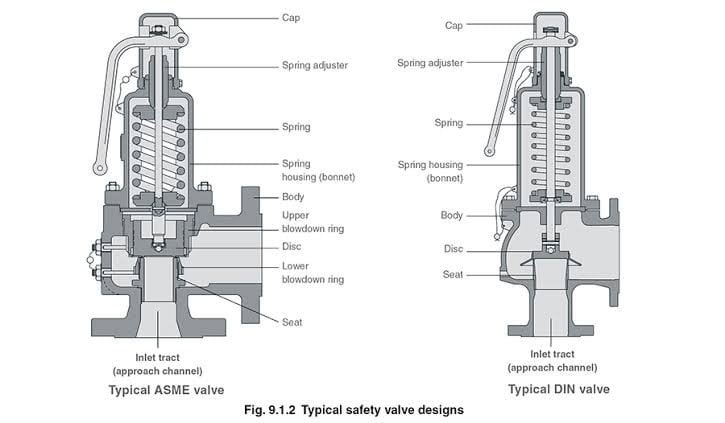
There is a wide range of safety valves available to meet the many different applications and performance criteria demanded by different industries. Furthermore, national standards define many varying types of safety valve.
The ASME standard I and ASME standard VIII for boiler and pressure vessel applications and the ASME/ANSI PTC 25.3 standard for safety valves and relief valves provide the following definition. These standards set performance characteristics as well as defining the different types of safety valves that are used:
ASME I valve - A safety relief valve conforming to the requirements of Section I of the ASME pressure vessel code for boiler applications which will open within 3% overpressure and close within 4%. It will usually feature two blowdown rings, and is identified by a National Board ‘V’ stamp.
ASME VIII valve- A safety relief valve conforming to the requirements of Section VIII of the ASME pressure vessel code for pressure vessel applications which will open within 10% overpressure and close within 7%. Identified by a National Board ‘UV’ stamp.
Full bore safety valve - A safety valve having no protrusions in the bore, and wherein the valve lifts to an extent sufficient for the minimum area at any section, at or below the seat, to become the controlling orifice.
Conventional safety relief valve -The spring housing is vented to the discharge side, hence operational characteristics are directly affected by changes in the backpressure to the valve.
Balanced safety relief valve -A balanced valve incorporates a means of minimising the effect of backpressure on the operational characteristics of the valve.
Pilot operated pressure relief valve -The major relieving device is combined with, and is controlled by, a self-actuated auxiliary pressure relief device.
Power-actuated safety relief valve - A pressure relief valve in which the major pressure relieving device is combined with, and controlled by, a device requiring an external source of energy.
Standard safety valve - A valve which, following opening, reaches the degree of lift necessary for the mass flowrate to be discharged within a pressure rise of not more than 10%. (The valve is characterised by a pop type action and is sometimes known as high lift).
Full lift (Vollhub) safety valve -A safety valve which, after commencement of lift, opens rapidly within a 5% pressure rise up to the full lift as limited by the design. The amount of lift up to the rapid opening (proportional range) shall not be more than 20%.
Direct loaded safety valve -A safety valve in which the opening force underneath the valve disc is opposed by a closing force such as a spring or a weight.
Proportional safety valve - A safety valve which opens more or less steadily in relation to the increase in pressure. Sudden opening within a 10% lift range will not occur without pressure increase. Following opening within a pressure of not more than 10%, these safety valves achieve the lift necessary for the mass flow to be discharged.
Diaphragm safety valve -A direct loaded safety valve wherein linear moving and rotating elements and springs are protected against the effects of the fluid by a diaphragm
Bellows safety valve - A direct loaded safety valve wherein sliding and (partially or fully) rotating elements and springs are protected against the effects of the fluids by a bellows. The bellows may be of such a design that it compensates for influences of backpressure.
Controlled safety valve - Consists of a main valve and a control device. It also includes direct acting safety valves with supplementary loading in which, until the set pressure is reached, an additional force increases the closing force.
Safety valve - A safety valve which automatically, without the assistance of any energy other than that of the fluid concerned, discharges a quantity of the fluid so as to prevent a predetermined safe pressure being exceeded, and which is designed to re-close and prevent further flow of fluid after normal pressure conditions of service have been restored. Note; the valve can be characterised either by pop action (rapid opening) or by opening in proportion (not necessarily linear) to the increase in pressure over the set pressure.
Direct loaded safety valve -A safety valve in which the loading due to the fluid pressure underneath the valve disc is opposed only by a direct mechanical loading device such as a weight, lever and weight, or a spring.
Assisted safety valve -A safety valve which by means of a powered assistance mechanism, may additionally be lifted at a pressure lower than the set pressure and will, even in the event of a failure of the assistance mechanism, comply with all the requirements for safety valves given in the standard.
Supplementary loaded safety valve - A safety valve that has, until the pressure at the inlet to the safety valve reaches the set pressure, an additional force, which increases the sealing force.
Note; this additional force (supplementary load), which may be provided by means of an extraneous power source, is reliably released when the pressure at the inlet of the safety valve reaches the set pressure. The amount of supplementary loading is so arranged that if such supplementary loading is not released, the safety valve will attain its certified discharge capacity at a pressure not greater than 1.1 times the maximum allowable pressure of the equipment to be protected.
Pilot operated safety valve -A safety valve, the operation of which is initiated and controlled by the fluid discharged from a pilot valve, which is itself, a direct loaded safety valve subject to the requirement of the standard.
The common characteristic shared between the definitions of conventional safety valves in the different standards, is that their operational characteristics are affected by any backpressure in the discharge system. It is important to note that the total backpressure is generated from two components; superimposed backpressure and the built-up backpressure:
Subsequently, in a conventional safety valve, only the superimposed backpressure will affect the opening characteristic and set value, but the combined backpressure will alter the blowdown characteristic and re-seat value.
The ASME/ANSI standard makes the further classification that conventional valves have a spring housing that is vented to the discharge side of the valve. If the spring housing is vented to the atmosphere, any superimposed backpressure will still affect the operational characteristics. Thiscan be seen from Figure 9.2.1, which shows schematic diagrams of valves whose spring housings are vented to the discharge side of the valve and to the atmosphere.
By considering the forces acting on the disc (with area AD), it can be seen that the required opening force (equivalent to the product of inlet pressure (PV) and the nozzle area (AN)) is the sum of the spring force (FS) and the force due to the backpressure (PB) acting on the top and bottom of the disc. In the case of a spring housing vented to the discharge side of the valve (an ASME conventional safety relief valve, see Figure 9.2.1 (a)), the required opening force is:
In both cases, if a significant superimposed backpressure exists, its effects on the set pressure need to be considered when designing a safety valve system.
Once the valve starts to open, the effects of built-up backpressure also have to be taken into account. For a conventional safety valve with the spring housing vented to the discharge side of the valve, see Figure 9.2.1 (a), the effect of built-up backpressure can be determined by considering Equation 9.2.1 and by noting that once the valve starts to open, the inlet pressure is the sum of the set pressure, PS, and the overpressure, PO.
Balanced safety valves are those that incorporate a means of eliminating the effects of backpressure. There are two basic designs that can be used to achieve this:
Although there are several variations of the piston valve, they generally consist of a piston type disc whose movement is constrained by a vented guide. The area of the top face of the piston, AP, and the nozzle seat area, AN, are designed to be equal. This means that the effective area of both the top and bottom surfaces of the disc exposed to the backpressure are equal, and therefore any additional forces are balanced. In addition, the spring bonnet is vented such that the top face of the piston is subjected to atmospheric pressure, as shown in Figure 9.2.2.
The bellows arrangement prevents backpressure acting on the upper side of the disc within the area of the bellows. The disc area extending beyond the bellows and the opposing disc area are equal, and so the forces acting on the disc are balanced, and the backpressure has little effect on the valve opening pressure.
Bellows failure is an important concern when using a bellows balanced safety valve, as this may affect the set pressure and capacity of the valve. It is important, therefore, that there is some mechanism for detecting any uncharacteristic fluid flow through the bellows vents. In addition, some bellows balanced safety valves include an auxiliary piston that is used to overcome the effects of backpressure in the case of bellows failure. This type of safety valve is usually only used on critical applications in the oil and petrochemical industries.
In addition to reducing the effects of backpressure, the bellows also serve to isolate the spindle guide and the spring from the process fluid, this is important when the fluid is corrosive.
Since balanced pressure relief valves are typically more expensive than their unbalanced counterparts, they are commonly only used where high pressure manifolds are unavoidable, or in critical applications where a very precise set pressure or blowdown is required.
This type of safety valve uses the flowing medium itself, through a pilot valve, to apply the closing force on the safety valve disc. The pilot valve is itself a small safety valve.
The diaphragm type is typically only available for low pressure applications and it produces a proportional type action, characteristic of relief valves used in liquid systems. They are therefore of little use in steam systems, consequently, they will not be considered in this text.
The piston type valve consists of a main valve, which uses a piston shaped closing device (or obturator), and an external pilot valve. Figure 9.2.4 shows a diagram of a typical piston type, pilot operated safety valve.
The piston and seating arrangement incorporated in the main valve is designed so that the bottom area of the piston, exposed to the inlet fluid, is less than the area of the top of the piston. As both ends of the piston are exposed to the fluid at the same pressure, this means that under normal system operating conditions, the closing force, resulting from the larger top area, is greater than the inlet force. The resultant downward force therefore holds the piston firmly on its seat.
If the inlet pressure were to rise, the net closing force on the piston also increases, ensuring that a tight shut-off is continually maintained. However, when the inlet pressure reaches the set pressure, the pilot valve will pop open to release the fluid pressure above the piston. With much less fluid pressure acting on the upper surface of the piston, the inlet pressure generates a net upwards force and the piston will leave its seat. This causes the main valve to pop open, allowing the process fluid to be discharged.
When the inlet pressure has been sufficiently reduced, the pilot valve will reclose, preventing the further release of fluid from the top of the piston, thereby re-establishing the net downward force, and causing the piston to reseat.
Pilot operated safety valves offer good overpressure and blowdown performance (a blowdown of 2% is attainable). For this reason, they are used where a narrow margin is required between the set pressure and the system operating pressure. Pilot operated valves are also available in much larger sizes, making them the preferred type of safety valve for larger capacities.
One of the main concerns with pilot operated safety valves is that the small bore, pilot connecting pipes are susceptible to blockage by foreign matter, or due to the collection of condensate in these pipes. This can lead to the failure of the valve, either in the open or closed position, depending on where the blockage occurs.
The terms full lift, high lift and low lift refer to the amount of travel the disc undergoes as it moves from its closed position to the position required to produce the certified discharge capacity, and how this affects the discharge capacity of the valve.
A full lift safety valve is one in which the disc lifts sufficiently, so that the curtain area no longer influences the discharge area. The discharge area, and therefore the capacity of the valve are subsequently determined by the bore area. This occurs when the disc lifts a distance of at least a quarter of the bore diameter. A full lift conventional safety valve is often the best choice for general steam applications.
The disc of a high lift safety valve lifts a distance of at least 1/12th of the bore diameter. This means that the curtain area, and ultimately the position of the disc, determines the discharge area. The discharge capacities of high lift valves tend to be significantly lower than those of full lift valves, and for a given discharge capacity, it is usually possible to select a full lift valve that has a nominal size several times smaller than a corresponding high lift valve, which usually incurs cost advantages.Furthermore, high lift valves tend to be used on compressible fluids where their action is more proportional.
In low lift valves, the disc only lifts a distance of 1/24th of the bore diameter. The discharge area is determined entirely by the position of the disc, and since the disc only lifts a small amount, the capacities tend to be much lower than those of full or high lift valves.
Except when safety valves are discharging, the only parts that are wetted by the process fluid are the inlet tract (nozzle) and the disc. Since safety valves operate infrequently under normal conditions, all other components can be manufactured from standard materials for most applications. There are however several exceptions, in which case, special materials have to be used, these include:
Cast steel -Commonly used on higher pressure valves (up to 40 bar g). Process type valves are usually made from a cast steel body with an austenitic full nozzle type construction.
For all safety valves, it is important that moving parts, particularly the spindle and guides are made from materials that will not easily degrade or corrode. As seats and discs are constantly in contact with the process fluid, they must be able to resist the effects of erosion and corrosion.
For process applications, austenitic stainless steel is commonly used for seats and discs; sometimes they are ‘stellite faced’ for increased durability. For extremely corrosive fluids, nozzles, discs and seats are made from special alloys such as ‘monel’ or ‘hastelloy’.
The spring is a critical element of the safety valve and must provide reliable performance within the required parameters. Standard safety valves will typically use carbon steel for moderate temperatures. Tungsten steel is used for higher temperature, non-corrosive applications, and stainless steel is used for corrosive or clean steam duty. For sour gas and high temperature applications, often special materials such as monel, hastelloy and ‘inconel’ are used.
A key option is the type of seating material used. Metal-to-metal seats, commonly made from stainless steel, are normally used for high temperature applications such as steam. Alternatively, resilient discs can be fixed to either or both of the seating surfaces where tighter shut-off is required, typically for gas or liquid applications. These inserts can be made from a number of different materials, but Viton, nitrile or EPDM are the most common. Soft seal inserts are not generally recommended for steam use.
Standard safety valves are generally fitted with an easing lever, which enables the valve to be lifted manually in order to ensure that it is operational at pressures in excess of 75% of set pressure. This is usually done as part of routine safety checks, or during maintenance to prevent seizing. The fitting of a lever is usually a requirement of national standards and insurance companies for steam and hot water applications. For example, the ASME Boiler and Pressure Vessel Code states that pressure relief valves must be fitted with a lever if they are to be used on air, water over 60°C, and steam.
A standard or open lever is the simplest type of lever available. It is typically used on applications where a small amount of leakage of the fluid to the atmosphere is acceptable, such as on steam and air systems, (see Figure 9.2.5 (a)).
Where it is not acceptable for the media to escape, a packed lever must be used. This uses a packed gland seal to ensure that the fluid is contained within the cap, (see Figure 9.2.5 (b)).
For service where a lever is not required, a cap can be used to simply protect the adjustment screw. If used in conjunction with a gasket, it can be used to prevent emissions to the atmosphere, (see Figure 9.2.6).
A test gag (Figure 9.2.7) may be used to prevent the valve from opening at the set pressure during hydraulic testing when commissioning a system. Once tested, the gag screw is removed and replaced with a short blanking plug before the valve is placed in service.
The amount of fluid depends on the particular design of safety valve. If emission of this fluid into the atmosphere is acceptable, the spring housing may be vented to the atmosphere – an open bonnet. This is usually advantageous when the safety valve is used on high temperature fluids or for boiler applications as, otherwise, high temperatures can relax the spring, altering the set pressure of the valve. However, using an open bonnet exposes the valve spring and internals to environmental conditions, which can lead to damage and corrosion of the spring.
When the fluid must be completely contained by the safety valve (and the discharge system), it is necessary to use a closed bonnet, which is not vented to the atmosphere. This type of spring enclosure is almost universally used for small screwed valves and, it is becoming increasingly common on many valve ranges since, particularly on steam, discharge of the fluid could be hazardous to personnel.
Some safety valves, most commonly those used for water applications, incorporate a flexible diaphragm or bellows to isolate the safety valve spring and upper chamber from the process fluid, (see Figure 9.2.9).

Pressure relief valves are a type of safety valve that are commonly used to protect a system and the people operating it. Whereas pressure regulators take incoming line pressure and regulates it down to the pressure that is required by the downstream system. Pressure Regulators can be used for reasons of safety and/or cost. Both of these valves are very important to its specific application. In this article, we will discuss the difference between a pressure relief valve and regulator.
Pressure Regulators take an incoming line pressure and regulate it down to the pressure that is required by the downstream system. This may be for other instrumentation to operate effectively or simply to control the output flow of a pipe. Lower system pressures mean less risk and lower running costs and a reduced risk of air loss through a system. Pressure regulators can be used in many applications including pneumatics, compressed air and water.
There are various kinds of pressure regulators available within MGA Controls range – from general purpose units covering everyday industrial applications to more specialised precision pressure regulators, manifold regulators, pilot operated regulators and large capacity pilot operated versions. View our full range of pressure regulators in our store.
Pressure relief valves are used to control or limit pressure spikes in a compressed air system. When the system pressure increases beyond a predetermined set point, the valve opens and relieves that pressure, bringing it back in line with normal operating parameters. The main function of a Pressure relief valve is to vent excess pressure and protect other system components, all the while maintaining optimum performance.
Air systems benefit highly from pressure relief valves, however different types of pressure relief valves can be used in a wide range of industries. For example, the water industry utilises the valve to make sure water pressure doesn’t reach such a level that it will burst pipes.
The IMI Norgren Olympian Plus pressure relief valve is designed to protect compressed air systems against over-pressurisation. It has high relief capacity while being sensitive and accurate. As part of the Olympian Plus range of products, it is suitable for in-line or modular installation and is compatible with other products in the Olympian Plus range, such as the B64G Filter/Regulator and the L64 Series Lubricator. Some of the key pressure relief valve features include:
Choosing a pressure relief valve isn’t always easy, but here at MGA Controls, we specialise in helping you choose the correct valve for your application. There are six basic factors to consider before choosing your pressure relief valve:
You must also consider the physical dimensions of the application and the plant, as well as factors related to the environment in which the valve will operate.
Here at MGA Controls, pressure relief valves can be fitted to an existing system and can be specified in sizes ranging from 1/4″ to 1.1/2″. We carry a wide range of stock that is available for quick delivery in your time of need.
To speak to a member of our technical team about choosing a pressure relief valve or the difference between a pressure relief valve and regulator contact us today on 01704 898980 or email sales@mgacontrols.co.uk. To request a free quote or view our general range of products contact our team.
RTDs are mostly made by platinum (Pt), since platinum has higher temperature withstanding capabilities and is more stable and repeatable compared to materials...
(a) The inlet opening shall have an inside diameter approximately equal to, or greater than, the seat diameter. In no case shall the maximum opening through any part of the valve be less than ¼ in. (6 mm) in diameter or its equivalent area.
(c) O-rings or other packing devices when used on the stems of safety relief valves shall be so arranged as not to affect their operation or capacity.
(d) The design shall incorporate guiding arrangements necessary to insure consistent operation and tightness. Excessive lengths of guiding surfaces should be avoided. Bottom guided designs are not permitted on safety relief valves.
(f) Safety valves shall be spring loaded. The spring shall be designed so that the full lift spring compression shall be no greater than 80% of the nominal solid deflection. The permanent set of the spring (defined as the difference between the free height and height measured 10 min after the spring has been compressed solid three additional times after presetting at room temperature) shall not exceed 0.5% of the free height.
(g) There shall be a lifting device and a mechanical connection between the lifting device and the disk capable of lifting the disk from the seat a distance of at least 1/16 in. (1.5 mm) with no pressure on the boiler.
(h) A body drain below seat level shall be provided by the Manufacturer for all safety valves and safety relief valves, except that the body drain may be omitted when the valve seat is above the bottom of the inside diameter of the discharge piping. For valves exceeding NPS 2½ (DN 65) the drain hole or holes shall be tapped not less than NPS 3/8 (DN 10). For valves NPS 2½ (DN 65) or smaller, the drain hole shall not be less than ¼ in. (6 mm) in diameter. Body drain connections shall not be plugged during or after field installation. In safety relief valves of the diaphragm type, the space above the diaphragm shall be vented to prevent a buildup of pressure above the diaphragm. Safety relief valves of the diaphragm type shall be so designed that failure or deterioration of the diaphragm material will not impair the ability of the valve to relieve at the rated capacity.
(k) The set pressure tolerances, plus or minus, of safety valves shall not exceed 2 psi (15 kPa), and for safety relief valves shall not exceed 3 psi (20 kPa) for pressures up to and including 60 psig (400 kPa) and 5% for pressures above 60 psig (400 kPa).
(l) Safety valves shall be arranged so that they cannot be reset to relieve at a higher pressure than the maximum allowable working pressure of the boiler.
(e) Material for valve bodies and bonnets or their corresponding metallic pressure containing parts shall be listed in Section II,except that in cases where a manufacturer desires to make use of materials other than those listed in Section II, he shall establish and maintain specifications requiring equivalent control of chemical and physical properties and quality.
(a) A Manufacturer shall demonstrate to the satisfaction of an ASME designee that his manufacturing, production, and testing facilities and quality control procedures will insure close agreement between the performance of random production samples and the performance of those valves submitted for capacity certification.
(c) A Manufacturer may be granted permission to apply, the HV Code Symbol to production pressure relief valves capacity certified in accordance with HG-402.3 provided the following tests are successfully completed. This permission shall expire on the sixth anniversary of the date it is initially granted. The permission may be extended for 6 year periods if the following tests are successfully repeated within the 6 month period before expiration.
(1) Two sample production pressure relief valves of a size and capacity within the capability of an ASME accepted laboratory shall be selected by an ASME designee.
(2) Operational and capacity tests shall be conducted in the presence of an ASME designee at an ASME accepted laboratory. The valve Manufacturer shall be notified of the time of the test and may have representatives present to witness the test.
(3) Should any valve fail to relieve at or above its certified capacity or should it fail to meet performance requirements of this Section, the test shall be repeated at the rate of two replacement valves, selected in accordance with HG-401.3(c)(1), for each valve that failed.
(4) Failure of any of the replacement valves to meet the capacity or the performance requirements of this Section shall be cause for revocation within 60 days of the authorization to use the Code Symbol on that particular type of valve. During this period, the Manufacturer shall demonstrate the cause of such deficiency and the action taken to guard against future occurrence, and the requirements of HG-401.3(c) above shall apply.
(d) Safety valves shall be sealed in a manner to prevent the valve from being taken apart without breaking the seal. Safety relief valves shall be set


 8613371530291