
harper wyman oven safety valve supplier
-Select-AfghanistanAlbaniaAlgeriaAmerican SamoaAndorraAngolaAnguillaAntigua and BarbudaArmeniaArubaAustraliaAustriaAzerbaijan RepublicBahamasBahrainBangladeshBelarusBelgiumBelizeBeninBermudaBhutanBosnia and HerzegovinaBotswanaBritish Virgin IslandsBrunei DarussalamBulgariaBurkina FasoBurundiCambodiaCameroonCanadaCape Verde IslandsCayman IslandsCentral African RepublicChadChinaComorosCook IslandsCosta RicaCyprusCzech RepublicCôte d"Ivoire (Ivory Coast)Democratic Republic of the CongoDenmarkDjiboutiDominicaDominican RepublicEgyptEl SalvadorEquatorial GuineaEritreaEstoniaEthiopiaFijiFinlandFranceGabon RepublicGambiaGeorgiaGermanyGhanaGibraltarGreeceGreenlandGrenadaGuamGuatemalaGuernseyGuineaGuinea-BissauHaitiHondurasHong KongHungaryIcelandIndiaIndonesiaIraqIrelandIsraelItalyJamaicaJapanJerseyJordanKazakhstanKenyaKiribatiKuwaitKyrgyzstanLaosLatviaLebanonLesothoLiberiaLiechtensteinLithuaniaLuxembourgMacauMacedoniaMadagascarMalawiMalaysiaMaldivesMaliMaltaMarshall IslandsMauritaniaMauritiusMayotteMexicoMicronesiaMoldovaMonacoMongoliaMontenegroMontserratMoroccoMozambiqueNamibiaNauruNepalNetherlandsNetherlands AntillesNew ZealandNicaraguaNigerNigeriaNiueNorwayOmanPakistanPalauPanamaPapua New GuineaPhilippinesPolandPortugalPuerto RicoQatarRepublic of CroatiaRepublic of the CongoRomaniaRwandaSaint HelenaSaint Kitts-NevisSaint LuciaSaint Pierre and MiquelonSaint Vincent and the GrenadinesSan MarinoSaudi ArabiaSenegalSerbiaSeychellesSierra LeoneSingaporeSlovakiaSloveniaSolomon IslandsSomaliaSouth AfricaSouth KoreaSpainSri LankaSwazilandSwedenSwitzerlandTaiwanTajikistanTanzaniaThailandTogoTongaTrinidad and TobagoTunisiaTurkeyTurkmenistanTurks and Caicos IslandsTuvaluUgandaUnited Arab EmiratesUnited KingdomUnited StatesUzbekistanVanuatuVatican City StateVietnamVirgin Islands (U.S.)Wallis and FutunaWestern SaharaWestern SamoaYemenZambiaZimbabwe

Antigua and Barbuda, Aruba, Australia, Austria, Bahamas, Bahrain, Bangladesh, Barbados, Belgium, Belize, Bermuda, Bolivia, Brazil, Brunei Darussalam, Bulgaria, Cambodia, Canada, Cayman Islands, Chile, China, Colombia, Costa Rica, Cyprus, Czech Republic, Denmark, Dominica, Dominican Republic, Ecuador, Egypt, El Salvador, Estonia, Finland, France, French Guiana, Germany, Gibraltar, Greece, Grenada, Guadeloupe, Guatemala, Guernsey, Honduras, Hong Kong, Hungary, Iceland, Indonesia, Ireland, Israel, Italy, Jamaica, Japan, Jersey, Jordan, Kuwait, Latvia, Liechtenstein, Lithuania, Luxembourg, Macau, Malaysia, Maldives, Malta, Martinique, Mexico, Monaco, Montserrat, Netherlands, New Zealand, Nicaragua, Norway, Oman, Pakistan, Panama, Paraguay, Peru, Philippines, Poland, Portugal, Qatar, Republic of Croatia, Reunion, Romania, Saint Kitts-Nevis, Saint Lucia, Saudi Arabia, Singapore, Slovakia, Slovenia, South Africa, South Korea, Spain, Sri Lanka, Sweden, Switzerland, Taiwan, Thailand, Trinidad and Tobago, Turks and Caicos Islands, United Arab Emirates, United Kingdom, United States, Vietnam

Frigidaire gas range oven safety valve. 3/8" inlet with 3/16" and 1/4" terminals. One of each size. 3203459, Y30128-35AF, 814412 ... More Info
Frigidaire gas range dual safety valve. 3/8" tubing inlet and lower outlet. Orifice hood upper outlet. The 5303208499 gas valve has the following numbers on the side: 0549A311962TNAT NC-4109-5 774111600012 Y-30172-2 ... It was made by Invens ... More Info
Whirlpool / Maytag oven safety valve. Low voltage oven valve for flat Norton ignitors. 3.0 - 3.3 volts. 3.3 - 3.6 amps. Adjustable orifice. Female terminals 3/8" tubing. ... More Info
Whirlpool / Maytag oven safety valve. Low voltage oven valve for flat Norton ignitors. 3.0 - 3.3 volts. 3.3 - 3.6 amps. Adjustable orifice. Female terminals 1/2" tubing. ... More Info
Exact Replacement Parts for Frigidaire gas range oven safety valve 3203459. 3/8" inlet with 3/16" and 1/4" terminals. One of each size. 3203459, Y30128-35AF, 814412 ... More Info

[52] U.S. C1 ..126/42, 126/39 E 511 Int. Cl. ..F24 3 12 [58] Field ofSeai-ch ..126/39 R, 39 C, 39 E, 39 G, 126/42; 236/99 [56] References Cited UNITED STATES PATENTS 3,469,781 9/ 1969 Sekera, Jr. ..236/99 FOREIGN PATENTS OR APPLICATIONS 339,639 12/1930 Great Britain 1 26/42 Primary ExaminerCharles J. Myhre Attorney-Mason, Kolehmainen, Rathbum & Wyss [57] ABSTRACT An oven control system and control valve for use with a gas oven including a main burner and a pilot burner serve to prevent operation of the oven when the oven door is opened. in normal operation, with the oven door closed, a valve member is moved to an open position in response to a predetermined pilot flame condition to admit gas to the main burner. When the oven door is moved to an open position. the valve member is held in its closed position to block flow to the main oven burner regardless of pilot flame condition.
IIVVEIVTOR. LEONA RD H. M/GHAELS BY M, xwwwfawwo A TTOR/VEYS OVEN CONTROL VALVE AND SYSTEM The present invention relates to an improved oven system and control for preventing operation of an oven burner in response to opening of the oven door.
In some situations it is highly desirable to prevent the operation of an oven burner while the oven door is open. For example, such an arrangement effectively prevents the use of an oven as a room heater, which use can cause oxygen depletion, fire hazards and the like. An arrangement for preventing operation of an ovenwith the door open is also useful in range heater combination units of the type provided in some mobile homes and the like. Units of this type are designed to utilize outside air for combustion, and if operated with the oven door open can cause a dangerous depletion of oxygen.
Among the important objects of the present" invention are to provide an improved oven control system wherein burner operation is prevented when the oven door is open; to provide an improved control valve for use in such a system; to provide a system which"is readily adaptable to existing range configurations andrwhich utilizes many existing components; to provide a system and valve capable of carrying out the desired function without otherwise interfering with operation of the oven; and to provide a control and system that is simple, economical and positive inoperation.
In brief, the-above and other objects and advantages are achieved in accordance with the present invention by the provision of an improved fuel control system for an oven of the type including a main burner and a pilot burner. The system includes a novel control valve for controlling the flow of fuel between a source and the oven burner. Associated with the valve isv a pilot flame responsive system for moving the valve from a nonnally closed to an open position in response to a predetermined pilot flame condition. In accordance with a feature of the invention, there is provided an operator means for moving the valve positively to a closed position in response to opening of the oven door thereby to prevent operation of the oven burner whenever the oven door is in an open condition.
FIG. 1 is a largely schematic and fragmentary simplified view of a gas oven including an oven control system and control valve embodying the principles of the present invention; and
Referring now to the drawings, in FIG. .1 there is illustrated a simplified and fragmentary portion of a range having an oven 12 equipped with an improved fuel control system designated as a whole by the reference numeral 14 and constructed"in accordance with the principles of the present invention. The system 14 includes an improved controlvalve generally designated as 16 constructed in accordance with the features of the present invention and illustrated in more detail in FIG. 2. The system 14 and valve 16 may be incorporated into any desired type of oven arrangement, and for purposes of example the illustrated oven 12 is shown incorporated into a free standing range 10 including a door 18 hingedly mounted upon an oven front wall 20 for movement between open and closed positions.
In order to heat the oven interior, there is provided a main oven burner 22 disposed beneath a flame shield 24 at the bottom of the oven 12. A pilot burner 26 located adjacent the main oven burner 22 serves to ignite fuel flowing from the main oven burner 22 and also serves to control the operation of the valve 16 thereby to control the admission of fuel to the burner 22 by heating a flame sensing bulb 28 during predetermined pilot flame conditions. In accordance with an important feature of the present invention, the novel fuel control system including the valve 16 prevents the admission of fuel to the main oven burner 22 when the oven door 18 is open regardless of-the pilot flame condition existing at the pilot burner 26.
The fuel control system 14 of the present invention is adaptable to many types of oven arrangements. In the"illustrated range 10, there is provided an oven control 30 of known construction connected to receive fuel from a manifold 32 and adapted to supply fuel to the pilot burner 26 by means of a pilot conduit 34 and to the valve 16 by means of a main gas conduit 36. The control 32 for example may be of the type disclosed in U.S. Pat. No. 3,423,021 of Frank l-L"Bergquist, and reference may be had to that patent for further information regarding the control 30 not necessary to an understanding of the present invention.
The control 30 includes an operating knob 38 which is ad-. justed by the user to select a desired oven temperature. The control is provided with a suitable temperature-sensing device (not shown) disposed in heat sensing relationship with the oven 12. When the sensed oven temperature is below the knob 38"temperature setting, fuel is made available to the pilot burner 26 to produce a pilot flame indication suflicient" to cause heating of the flame sensing bulb 28 and operation of the valve 16. Simultaneously, the control 30 supplies fuel to the valve 16 by way of the main gas conduit 36. In" normal operation with the door 18 closed, the valve 16 opens to admit fuel to the main oven burner 22.
Conversely, when the demand for heat within the oven is satisfied, the control 30 is effective to terminate the flame in-. dication at the pilot burner 26 whereupon the flame sensing bulb 28 cools and the valve 16 controlled thereby discontinues the flow of fuel to the oven burner 22. It will be readily understood by those skilled in the art that a small standby flame for re-ignition of the pilot flame indication at the burner 26".
In accordance with an important feature of the invention, regardless of the pilot flame condition existing at the pilot burner 26, when the oven door 18 is moved from its closed to its open position, the control l6"is placed in a condition such that fuel is not admitted to the oven burner 22. For this pur-. pose there is provided means operatively coupled between the door 18 and the valve 16" which in the illustrated embodiment of the invention takes the form of a mechanical linkage generally designated as 40. The door 18" is provided with a conventional guide and stop member 42 to which there is connected a conventional counterbalancing spring 44. The linkage 40 includes a tension element in the form of a wire. or cable 46 provided with a spring 48 serving to provide for overtravel and to maintain tension on the cable 46. The cable 46" is connected between the guide 42 and an operating lever 50 mounted on a suitable pivot 52 and serving to apply an operating force to the valve 16 when the oven"door is moved to its open position.
With reference to FIG. 2, the construction of the valve 16" is illustrated. The valve includes a housing 54 having an inlet 56 adapted to receive fuel from the main gas conduit 36 and an outlet 58 adapted to be coupled to the inlet of the main gas burner 22 in order to supply fuel for operation of the. burner. Disposed between the inlet 5 and the outlet 58 is a valve seat. 60, and a valve member 62 is movable into and out of sealing engagement with the seat 60 in order to control the flow of fuel through the housing.
Under normal operating conditions when the oven door 18 is closed, the position of thevalve member 62Iis controlled by a flame sensing system generally designated as 64 and including the flame sensing bulb 28 located adjacent the pilot burner 26. The bulb 28 is communicated with an expansible diaphragm 66 located within the housing 54 by means of a capillary conduit 68. The region defined within the diaphragm 66, capillary conduit 68 and bulb 28 is charged with a suitable heat expansible medium to the end that when the bulb-28 is heated in response to a predetermined pilot flame condition, the diaphragm 66 expands and a power element 70 pivots a lever 72 in"a direction to move the valve member 62 away from the seat 60.
Normally the valve member 62 is held in closed position in contact with the seat 60 by a spring 74. When the lever 72 pivots, the valve member 62 is moved away from its seat against the force of the spring 74. The lever 72 is coupled to the valve member 62 by means of a sliding drive member 76 normally held in its illustrated position by means of an overtravel spring 78. The spring 78 is a stiffer spring than the spring 74 to the end that spring 78 is not compressed as valve 62 is moved to its open position. However, in the event of overtravel of the lever 72 after full opening of the valve, the spring 78 compresses to permit movement of the lever 72 independently of the valve member 62. In some respects the valve 16 may be of known construction, and reference may be had to U.S. Pat. No. 3,469,781 of George F. Sekera, Jr. for further information regarding those aspects of the valve 16 not necessary to an understanding of the present invention.
Mounted for sliding movement in a fitting 80 supported on housing 54 is an operator 82 having an enlarged head 84. As can be seen in FIG. 1, the head 84 is adapted to be depressed by the lever 50 when the oven door 18 is opened. Normally the operator 82 is held in its illustrated fully extended position by means of a spring 86 and the movement of the valve member 62 between its fully open and fully closed positions is not impeded. If desired, as in the illustrated arrangement, the operator 82 may include an innermost portion 88 serving as a guide for the normal opening and closing movement of the valve member 62.
When the oven door is opened, the lever 50 engages and depresses the head 84 against the force of the spring 86. As a result, a drive member 90 mounted upon the operator 82 engages the valve member 62 and forces the valve member 62 toward its closed position. In the event that the valve member 62 is in its open position when the oven door is opened, the valve member 62 is moved to its closed position. This movement is permitted by the overtravel spring 78 which compresses to the necessary extent. Alternatively, in the event that the valve member 62 is in its closed position when the oven door is opened, the valve member 62 is held in its closed position and does not open even if the predetermined pilot flame indication thereafter exists since movement of the lever 72 with the operator 82 depressed does not result in opening of the valve member 62 but only in compression of the overtravel spring 78.
When the oven door is again closed, the system returns immediately to normal operation without the necessity for any further steps on the part of the operator. If upon closure of the oven door the control is calling for heat and the bulb 28 is heated by the predetermined pilot flame indication, the valve member 62 moves immediately to its open position under the force of the compressed overtravel spring 78. Alternatively, in the event that the flame sensing bulb 28 is not heated when the oven door is closed, the operator 82 simply withdraws to the position illustrated in FIG. 2 wherein the valve 62 may thereafter be opened in the normal manner.
said valve means including a valve seat and a valve member movable into and out of sealing engagement with said valve seat; a pilot burner means disposed adjacent the main burner; flame sensing means mounted in heat sensing relation to said pilot burner means and coupled to said valve member for moving said valve member out of sealing engagement with said valve seat in response to a predetermined pilot flame condition thereby to permit the admission of fuel to the main burner; and
operator means coupled between said valve member and said door for moving said valve member into sealing engagement with said valve seat in response to opening of said door to prevent the admission of fuel to the burner regardless of pilot flame condition.
3. The system of claim 1, further comprising thermostatic control means for controlling the flow of fuel to said pilot burner and to said valve means.
4. A control valve for use in a gas oven of the type including a door movable to closed and open positions, a main burner, and a pilot burner, said control valve comprising:
a housing including an inlet adapted to be communicated with a source of gas, an outlet adapted to be coupled to supply gas to the main burner, and a valve seat disposed between the inlet and outlet; coupled a valve member in said housing and a spring means normally urging said valve member into engagement with said valve seat to block flow between said inlet and said outlet;
a flame sensing system coupled to said valve member for moving said valve member away from said valve seat to permit flow between said inlet and outlet in response to a predetermined pilot flame condition; and
oven door position responsive means operatively coupled to the oven door and to said valve member for moving said valve member into engagement with said valve seat upon opening of said oven door to block flow of gas between said inlet and outlet independently of the pilot flame condition.
5. The control of claim 4, said flame sensing system including a lever pivotally mounted in said housing on one side of said valve seat for moving the valve member away from the valve seat, and said oven door position responsive means including movable operator means mounted at least partly in said housing on the other side of said valve seat and engageable with said valve member for moving said valve member toward said valve seat.
8. A control valve for a gas oven including an oven door, an oven .bumer and a pilot burner, and comprising a housing defining a valve seat for supplying gas to the oven burner; a valve member; first spring means normally urging the valve member to a closed position in engagement with the valve seat to block flow to the burner; pilot responsive means engageable with the valve member to move the valve member to an open position spaced from the valve seat in response to a predetermined pilot burner flame condition; said pilot responsive means including overtravel means including an overtravel spring permitting independent movement of the valve member and a pilot responsive means, said overtravel spring being stiffer than said first spring; and oven door position responsive means engageable with the valve member for moving the valve member to its closed position in response to opening of the oven door.

Limitations : For products shipped internationally, please note that any manufacturer warranty may not be valid; manufacturer service options may not be available; product manuals, instructions, and safety warnings may not be in destination country languages; the products (and accompanying materials) may not be designed in accordance with destination country standards, specifications, and labeling requirements; and the products may not conform to destination country voltage and other electrical standards (requiring use of an adapter or converter if appropriate). The recipient is responsible for assuring that the product can be lawfully imported to the destination country. When ordering from Ubuy or its affiliates, the recipient is the importer of record and must comply with all laws and regulations of the destination country.
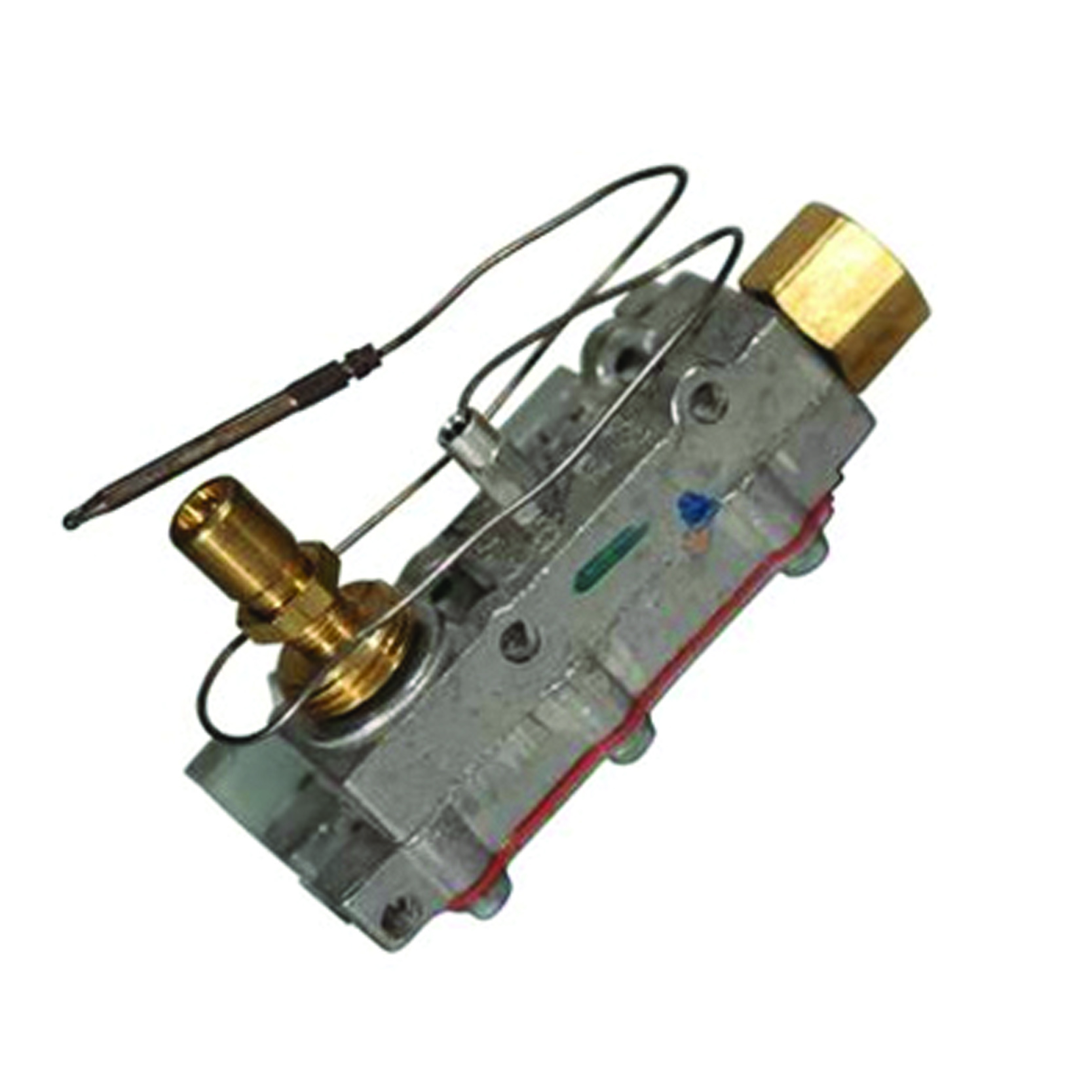
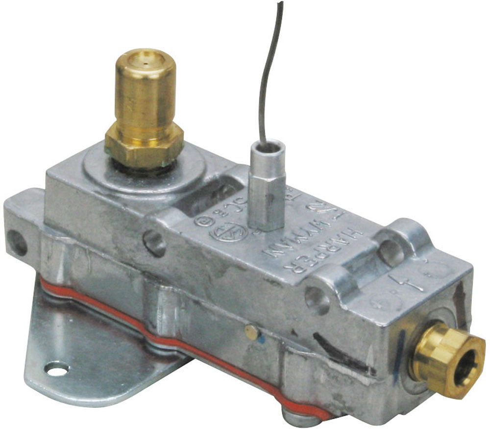
NEW HARPCO Harper Wyman Range Oven Thermocouple and Safety Valve 5800S0005 VTG. [zipedit] Details All of our used parts have been tested while installed in the original appliance by one of our skilled and knowledgeable technicians. Typically, our items are photographed on a 1x1 inch grid. You can determine the item"s rough dimensions by counting the squares on the grid. Part Compatibility We DO NOT sell parts for trial and error and would much rather see to it that you receive the proper part you need to repair your appliance the first time around. Should you not be able to sort it out on your own, or if you aren"t sure what exactly is wrong with your appliance, feel free to send us a message through eBay. Be sure to include your Model Number and Serial Number, along with a description of what is wrong with your appliance. We will try to help you diagnose the issue and get your appliance back up and running in a timely manner. Returns You may return any part for 30 days, however, you will be subjected to a 20% restocking fee. The restocking fee helps cover the cost of the time and effort involved in reprocessing the item, and the original cost of shipping and supplies. Please note that any electrical parts cannot be returned once they"ve been installed on the appliance. This is a standard policy among appliance parts dealers. If you wish to make a return, please use the return system provided under your purchase history on the eBay website. Please contact us if your part arrived damaged or is non-functioning before attempting a return. We will figure something out. About Us We have been in the used appliance business for over 15 years, and are a proud member of the Better Business Bureau. Please feel free to contact us with any questions, just search for us on Google.
Condition: New, BIN Location: 4545, Model: 5800S0005, MPN: 5800S0005, Type: Thermocouple/Safety Valve, Brand: Harper-Wyman, Compatible Brand: Harper-Wyman


 8613371530291