
harper wyman safety valve manufacturer
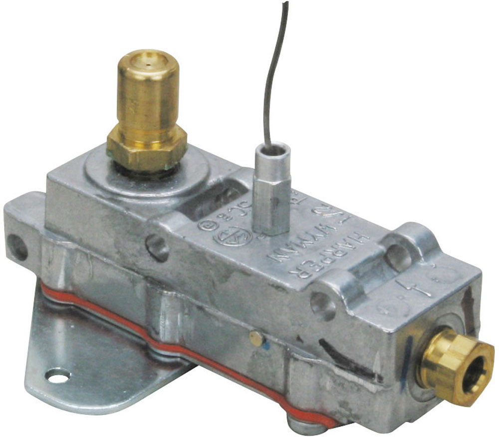
New Harper Wyman oven safety valve part# 5815H0033A.This comes complete with the orfice.This is the same as 5815S0033,5815H0012,5815H0001,5815H0007 AND 997411.WAS 125.00 NOW 100.00856**649**FIVE 74 Three ...
New Harper Wyman oven safety valve part# 5815H0033A.This comes complete with the orfice.This is the same as 5815S0033,5815H0012,5815H0001,5815H0007 AND 997411.WAS 125.00 NOW 100.00856**649**FIVE 74 Three ...
Harper Wyman Gas Range Oven Thermostat, model #WB20K8. Approximately 150 new thermostats. Owner of a small appliance company is in the process of cleaning house and has found to have excess inventory of some items. Price is negotiable, please call or e-mail for more information ...
Harper Wyman Gas Range Oven Thermostat, model #WB20K8. Approximately 150 new thermostats. Owner of a small appliance company is in the process of cleaning house and has found to have excess inventory of some items. Price is negotiable, please call or e-mail for more information ...
Harper Wyman Gas Range Oven Thermostat, model #WB20K8. Approximately 150 new thermostats. Owner of a small appliance company is in the process of cleaning house and has found to have excess inventory of some items. Price is negotiable, please call or e-mail for more information ...
Harper Wyman Gas Range Oven Thermostat, model #WB20K8. Approximately 150 new thermostats. Owner of a small appliance company is in the process of cleaning house and has found to have excess inventory of some items. Price is negotiable, please call or e-mail for more information ...
Text or call with any questions, the number is below.Numatics Lockout Air Safety Valve VT30N04Y Slo-Start 150PSIG Pneumatic Emergency Shut off control unitThis one looks to be in Good shape! Nice used condition 1/2" NPT Pipe thread ports Quick shutoff safety valve ...

Limitations : For products shipped internationally, please note that any manufacturer warranty may not be valid; manufacturer service options may not be available; product manuals, instructions, and safety warnings may not be in destination country languages; the products (and accompanying materials) may not be designed in accordance with destination country standards, specifications, and labeling requirements; and the products may not conform to destination country voltage and other electrical standards (requiring use of an adapter or converter if appropriate). The recipient is responsible for assuring that the product can be lawfully imported to the destination country. When ordering from Ubuy or its affiliates, the recipient is the importer of record and must comply with all laws and regulations of the destination country.

NEW Harper Wyman Safety Valve 161162 2B5E Gas Range Oven *FREE SHIPPING*. YOU ARE BIDDING ON A: Harper Wyman Safety Valve 161162 2B5E Gas Range Oven Location: TOTE 315 *PLEASE READ* Due to the nature of the items we sell, we may only have one in stock. Because many items are genuine manufacture"s new old stock, they are in limited supply. Once it"s sold, its gone, and we may never get another item exactly like it. PER EBAY RULES, CONDITION IS STATED AS FOLLOWS: New: A brand-new, unused, unopened, undamaged item in its original packaging (where packaging is applicable). Packaging should be the same as what is found in a retail store, unless the item is handmade or was packaged by the manufacturer in non-retail packaging, such as an unprinted box or plastic bag. See the seller"s listing for full details. New other (see details and photos): A new, unused item with absolutely no signs of wear. The item may be missing the original packaging, or in the original packaging but not sealed. The item may be a factory second or a new, unused item with defects. See the seller"s listing for full details and description of any imperfections. Manufacturer refurbished: An item that has been professionally restored to working order by a manufacturer or manufacturer-approved vendor. This means the product has been inspected, cleaned, and repaired to meet manufacturer specifications and is in excellent condition. This item may or may not be in the original packaging. See the seller"s listing for full details. Seller refurbished: An item that has been restored to working order by the eBay seller or a third party not approved by the manufacturer. This means the item has been inspected, cleaned, and repaired to full working order and is in excellent condition. This item may or may not be in original packaging. See the seller"s listing for full details. Used: An item that has been used previously. The item may have some signs of cosmetic wear, but is fully operational and functions as intended. This item may be a floor model or store return that has been used. See the seller"s listing for full details and description of any imperfections. For parts or not working: An item that does not function as intended and is not fully operational. This includes items that are defective in ways that render them difficult to use, items that require service or repair, or items missing essential components. See the seller"s listing for full details. Communication between the buyer and seller is a VERY important step to assuring that all transactions run smoothly. If you have any questions, comments or concerns, PLEASE contact us directly through eBay. Questions sent through Paypal after a transaction is completed will NOT be answered. We have listed all model information that we have available. We strive to provide all information that we have on hand and do our best to describe and photograph every part. We cannot guarantee that this part will fit your application, only an authorized dealership can do that. Please make sure that this is the correct part that you need BEFORE you buy. The best way to do this is to call a dealership and have them verify that this is the appropriate part number for your application. *THE FREE SHIPPING OFFER APPLIES TO THE CONTINENTAL UNITED STATES ONLY. RESIDENTS OF ALASKA, HAWAII AND PUERTO RICO WILL NEED TO EMAIL US FOR AN ACCURATE SHIPPING QUOTE. WHEN CONTACTING US FOR INTERNATIONAL SHIPPING, PLEASE PROVIDE A POSTAL CODE FOR THE FASTEST RESPONSE. * TERMS * The overwhelming majority of what we sell is surplus from large companies or governments. If we say the item works, then it was tested to the best of our ability. All items and contents are described to the best of our ability. We examine all items and supply all available make/model information. We will try to answer all questions in a timely manner. * PAYMENT * All payment is due immediately with the "Buy It Now" feature. All payments are processed for fulfillment immediately, through PayPal"s policy. If you pay by PayPal, we will ONLY ship to the PayPal confirmed or approved shipping address that you choose at the time of payment. * SHIPPING & HANDLING * For normal orders, orders ship between 1 to 3 business days after payment is made. We cannot control shipping time after we ship. Most items are shipped through USPS, with a tracking number. If an item ships via any other method, shipping/tracking information, as well as the carrier will be provided. Please do not leave USPS problems in our feedback AC Powered by eBay Turbo ListerThe free listing tool. List your items fast and easy and manage your active items.

n 9`Claims. 1 The present inventionrelat"es to gas valves and more particularly to the vprovision ofgas valves "with new and"improvedvalveipositioning and indicating means.
The primary"ob-ject oi the present invention is to provide a new and improved gas valve positioning l and indicating vmechanism which is sim- `ple and compact in construction, and, more spe- "ci1ically, `sufficiently compact so that it may be lreadily utilized with `valves having threaded or bayonetlocl; type top caps.Y
Another of the-primary objects of the present kinvention is theprovision oa new and improved positioning and `indicating "mechanism for a tplural position"gas valve, and especially a mechanism -for Vindicating high and low positions of a "valve 4of the type commonly called a "high-low "vali/e.
A further object of the present invention is the provision "of Vanew and improved valve positioning and indicating mechanism capable of producingfan audible indication when the valve :substantially in its full on position.
-Another object of the present invention is the provision of a new and improved positioning and indicating"mechanism for a high-low valve capable of producing an audible indication, such as a lclick,when the valve is in a position supplying fsuiiicient gas iOr"ignitiOn, and producing resist- A-`ance to movement when the valve is in another loperating position, i. e., the lowposition.
"A"further and more specic object ofthe present inventionis "to provide a new and improved "ifalve lpositioning and indicatingmechanism including"a vpair of discs or plates rotatable with "tli"e valveorvalvestem and"one oi which is only friction"ally connectedto the valve stem for move- I"mentwitliii"., whercby"the two plates are anguar- -l-yfm"ovable withrespect to .each other, andsaid yone `plate being "movable longitudinally of `the "stemto"providelanaudible indication of one Valve -posito"niand also restraining angular movement --oi"the"othe1"plate.to determine and indicate the other valve .position.
Fig. 1 is an axialcross-sectional `view through a Valveincludingthe positioning and indicating .mechanism of the presentinvention, `the usual Valve operating "handle `being omitted :for the sake ACifsimplicity;
` Fig. .l2-is an .exploded view of a portioniof the vahfeillus"trated "in Fig. 1 ,fshowing .the various 1 :parts rand construction "of the novel "positioning l2 and indicating mechanismof the invention. "The parts "are illustrated in "the positions occupied by them when the valve isin-itsoff position;
Fig. 3 is a fragmentary cross lsectional view takenalong theline 3--3 of Fig. l. The valve"is in an intermediate"the lowposition, in both Vo1" these iigures;
Fig. 5 is a view similar to Figs. 3 rand 4, Vwith the -valve "in -a "position just v.prior -to the vproduction of anaudibleindicationthat suflicientgas"is being supplied for good ignition;
Figs. 11, 12, 13 and `11i-are -viewssimilar to Fig. 3, illustrating `the valve-in its 01T .fposition, a position just prior to the production of an audible click indicating `that suicient gas is Abeingsupplied fcr good ignition, -a :position Whereat "an audible indication is produced, and the ffull on position, respectively. n
The present invention has .been :illustrated -in conjunction withLa plural )position gas valve lil of the type commonly-called.high-low valve. The valve includes a rotatable tapered valveplug I2 movable from an oi ,position, wherein no kgas flows through the valve,to ,high and-low positions wherein different-quantities of gas flow` to the burner, and to an-intermediate positionsubstantially at the full onfposition wherea"tanaudible indication -is given ofthe passage-of. sufficient gas for good ignition. In the high position, a larger quantity of"gasvlows to the burner and in the low position a smallerv quantity ofgas ows to the burner. The valve includes a body Hiwithin which theplug isrotatably mounted in conventional manner.
Gas is supplied to the `valve-from aisuitable source of gas (not shown) through a manifold I6 and regulated vkquan-titiesofgas f"aresupplied to a burner, not. shown, which-is"conhectedto the outlet of the valve"throughwa "mixing tube|8, which may be of conventional construction. "The the plug and opening at its outer end to the chamber 22.
As heretofore indicated, the valve is of the plural position type. In one angular position of the plug,`a larger quantity of gas is supplied to the valve and in another (the low position) a smaller quantity. In the former of the two positions, the inlet and outlet passageways 3i) and 36, respectively, are interconnected through a relatively large sized radial passageway 38 extending from the exteriorsurface of the valve plug to the axial passageway 35. In the illustrated valve, sufiicient gas for good ignition flows through the valve at a valve position somewhat short of the full on position, i. e., shortly before the passageways 30 and 3S are fully aligned. In the low position, a preadjusted smaller quantity of gas flows tothe axial passageway from the inlet passageway through a two-part passageway 40 extending generally radially through the valve plug and an auxiliary adjustable low adjustment valve 42 having an axial passageway 44 communicating with the passageway 35 in the valve plug and a radial passageway 46 connecting the passageways 48 and 44.
The auxiliary adjustable valve is movably mounted in gas-tight manner within an intermediate passageway 48 in the valve plug, and is provided with a slot i! at its outer end whereby "it may be rotated to adjust the effective size of the orifice formed by the passageways 4U and 46 in the plug and auxiliary valve, respectively. The slot 50 is accessible through an axial passageway 52 in the valve stem 54, which, in the instant embodiment, is an integral part of the valve plug. The adjustment of the quantity of gas flowing in the low position may easily be effected after the usual valve handle, not shown, has been detached from the stem. The stem or low adjustment illustrated and described immediately above forms no part of the present invention, it being disclosed and claimed in the copending application of Philip S. Harper, Serial No. 576,673, led February 1945, and assigned to the assignee of this application.
The novel positioning and indicating mechanism of the present invention is housed within a top cap 68 detachably secured to the valve body. It is preferable, but not necessary, that the top cap be detachably secured by a bayonet lock type connection. The top cap is generally cup-shaped and has a central aperture S2 through which the valve stem 54 passes freely. The cap has a pair of diametrically opposite inwardly extending lugs 64 cooperating with generally J-shaped passageways 66 on the exterior of the valve body to provide the bayonet lock type detachable connection." Y
Referringparticularly to Fig. 2, it may be noted valve body onto the slots E6, after which iit"can until the lugs 64 are opposite the shorter ends 68 of the J-shaped slot 66 whereat the cap is moved outwardly and thus securely held by a short helical spring 10 surrounding the valve stem. One end of the spring bears against a shoulder 1 2 at the larger diameter end of the tapered portion 34 of the valve plug and the other exerts an outward force upon the top cap through a plurality of discs or plates 80, 82, and 84 con prising the novel positioning and indicating mechanism o f the present invention. If desired plates 89 and 84 may be combined in a single plate, as described in the embodiment of the invention disclosed Figs. 8 to 13, inclusive.
The positioning and indicating mechanism of the present invention may be constructed simply and economically, and may be readily housed within a portion of the valve body and the top cap. It is preferred that themechanisml determine and"indicate a pluralityy of positions of the valve. In the instant embodiment of the inven tion the mechanism produces an audible indication or click when the gas valve is operated to a position whereat suiiicient gas for ignition supplied to the burner, and another, the low posi tion is indicated by restraint of movement of the valve. Two other positions, the on and fullon positions, are determined and indicated by positive restraint of movement of the valve.
The novel mechanism includes a pair of discs or detent plates, one of which is constrained for movement with the valve plug and preferably the valve stem, and the other of which is frictionally movable with the stem through a predetermined angular distance, after which it is prevented from moving and the other plate moves angularly with respect to it. After such relative movement has occurred for a predetermined distance in one direction, the frictional plate moves toward and engages the other so as to produce an"audible sound, and when the relative movement is in the opposite direction, the frictional plate restrains but does not prevent movement of the other plate.
Returning again to -the drawings, it may be noted that the valve body is provided with a longitudinally extending arcuate projection 85, the shoulders 86 and 88 of which are spaced apart a predetermined distance to determine the extent of angular movement of the valve. In the illustrated embodiment of the invention, the shoulders are spaced apart a distance of substantially 180. The extension 85 is radially spaced from the stem outwardly a sufficient distance to accommodate at least the plates and 82 which haveradial extensions 90 and 92, respectively, cooperatively associated with the shoulders 86 and 88, as will become more apparent shortly. The plates 8D and 84 are constrained to rotate with the"valve, preferably, by providing them with generally D-shaped apertures, the ats 94 and 96 of which, respectively, engage a corresponding iiat 98 on the valve stem 54. The outer end of the valve stem is flattened as indicated by reference character |00 non-rotatably to receive a valve operating handle, not shown.
The off and full on positions of the valve are determined by the washer 80,.which is constrained to move with the valve and valve stem. "I"hese positions are determined and indicated by the engagement of the extension 90 of the plate with Vthe shoulders 86 and 88, respectively. The"off position is indicated in Fig. 4, from which it .may be noted that the extension 90 is in engagement be locked on the body by moving it angularly A.,"Uiywitli shoulder .8.8, :":Ifhe fulln position is shown in Fig. 7, from which vitmay be noted that extension-90 is `in engagement Awith the lotherfshoul- The twolplates 82 and 84 are providedf-"Witha plurality, preferably. at-least three,` ofaxial projectionsmaintaining the two plates in spaced relation under certain conditions ,and impositively restraining movement of one plate relative" tothe other under other conditions. A"The projectionsin plate 82 are indicated bythe reference character l Y|02-v and those in the plate 84 by referenceicharacter |04. The projections may be of `various constructions, but it is-preferred that they"besubstantially V-shaped radial grooves stampedor -otherwise"formed in the plates. In the illustrated engage plate 84, thereby toproduce the audible indication. This audible indication is produced, as heretofore indicated, when the valveA plug |2 is turned 4toa position .Whereatthe"burner is 4supplied with suicient gas for .goodignition Preferably, this position is close to the"full on yposition.
AIn the offposition of the valve, illustrated-in Fig.. 4, it maybe noted that the plate 82l is "main- ^tainedv out of substantial engagement With plate 84 by the projections |04 which are out of alignment with the projections |02. In this position the radial extensions 98 and 92 of the stop-and frictional plates 80 and 82.are both in engagement with shoulder 86. When the valve stem is moved counterclockwise, as viewed in Figui,- to the position illustrated in Fig. 5, the three plates move as a unit. "Plates 80 and 84 are constrained positively to move with the valve stemvvhile plate 82 moves in unison with theothers because it is frictionally held between them. This unitary movement occurs until the radial extension 92 in plate 82 strikes the shoulder 88, as villustrated"in Fig. 5. Further counterclockwise movementoi` the valve now results only in the movementof plates 80 and 84, With the result that projections |02 and |04 in plates 82 and 84 approach alignr.ment and the spring "i0 finally and suddenly moves plate 82 outwardly along the stem to bring the projections |02 and |04 into what may be considered a nesting position, as illustrated in Fig. 6.
After the burner has ignited, the valve may be turned to the full on position or to a low position. Movement of the Valve to the full on position is accomplished by rotating the valve `further in a counterclockwise direction to the Dositionillustrated in Fig. 7. In this position,lboth radial extensions 00 and 92 are in engagement -6 with the shoulder 88 all three of the plates moving Jf asial -nnit during this furthercounterclock- "wise movement.
To joperate l,thefvalveto its low position from eitherthe ignition ofi fullron` positions, the; valve Mplug, is rotated. in La clockwise direction. During such movement. the three platesumove L as i a unit with the valvestem. Plates :.andf` 84;;areicon- I strained positively to moveiwth: the. valvefrwhile the plate 82 is impositively. constrainedsol to"move .because of the inested relationship between fthe vplates 82 and 84.
Tomove the-valve Yto its oil?.` position,i.theplug is lmovedlfurther in. a clockwisel direction"from the position nwhich it is` shown inlFig.l3 tothe postion in .which it is Vshown in"Figs." 2 and4.
*further movement can` be. accomplishedbnlyl by the.exertionsofsuicient forceV to cam plate`82 axiallyinwardly. andl away from-plate84. When vthe valve lplug is turned,.plate 82Lis prevented "from turning" bythe engagement between-extension 92l andfshoulderi-861While.plate;84 turns with the valve` stem. k*After the plates have .been cammed apart, the projections |041oflplatel84 nride"on the-surface of platei82 `until extension 90 of the :stop plate also engages the shoulder 86. as illustrated ini Fig. 4.
combining.thelfunctions-oidiscs.80s-and 84 of the In ,other words, the "disc |`|0 :performs :the `function .of the positioning and indicating.dismandalsothe lafunctions. of the :disc 180;,in determining Vthe Afull i on"iandoff.positionszofitheivalve.
The `disc |;|.0; is located. .inwardly;oif the disc ,82, .as may ".bezbestgnotedjfrom. Figs. "18, and. 9. .Itlhas 4ajflat A| I2 econstrainingit :onrotation with the valve and valve stem. It also has a short radial extension ||4 cooperatively associatedwiththe shoulders .88"and 88 on"thevalve body;for indicatingthef"fullon andoi positions .bygpositivexe- :sti-aint ".to :further firnovement of .the :valve "and .valve istem. It ,in"cludesalso :a :plurality nf :projections H8 cooperatively 4associated with .the Vprojections v|02 ofthediscz82.
Itlisbelieved thatlthe yoperationoithefernbodi- VAment of the invention illustrated "ini Figs. 8 :to -.13 willbe:apparent,:fromLtheoregoingbrieidescrip- "tion .of the `detailed construction `-but ,it :will :be reviewed .zbri"ey ".The :off and riull :onxpositions of :the "1v-awe are :determined :byzthediso H0 more particularly, fthe ,radial `:extension :H4 thereof, which Iengages the shoulders 83" and 88. The off position is illustrated in Fig. 11. In this position, the radial extension H4 abuts against the shoulder 86 thereby limiting clockwise movement of the valve. The full on position is illustrated in Fig. 14, in which the radial extension H8 is in engagement with the shoulder 88, thereby positively restraining counter-clockwise movement of the valve. It may be noted also that in the off position, the
When the valve is turned from its off position toward the full on position, the detent disc H is positively turned with the valve while the detent disc 82 is moved because of its frictional engagement with the other disc. The two discs rotate simultaneously until the radial extension 92 in the disc 82 strikes the shoulder 88 (see Fig. 12), after which the disc I I8 alone turns with the valve. As a result, the projections IIS in the disc IIS approach the projections I02 in the disc 82 until they are almost in alignment, which is the case just before the audible indication is produced to indicate the flow of suflicient gas for good ignition.
After the indication has been produced, the valve may be moved either to the full on position indicated in Fig. 14 or returned to the low position indicated in Fig. 10. In either case the two discs 82 and H8 move as a unit. Movement beyond the full on position is positively restrained by the radial extension H4 while movement beyond"the low position is only impositively restrained.
The valve may be moved to the off position indicated in Fig. ll from the low position indicated in Fig. upon the application of suicient turnl ing moment to force the detent disc Il radially inward and away from the disc 82 by disaligning the projections I2 and Ii.
1. A multi-position gas valve of the type including spaced apart stationary stop defining shoulders and a member movable angularly to different positions indicative of the position of the valve, including in combination, a first detent plate mounted on said member and constrained for angular movement therewith, a second detent plate movably mounted in contact With the rst plate and movable angularly relative to and with said rst plate and member, said second .plate having a radial extension having an angular extent less than the distance between said shoulders and movable between and engageable with the shoulders, and means including complementary angularly spaced apart axially extending frictional driving portions on said plates and axially acting spring means for resiliently urging the two plates into frictional contact with each other so that said second plate is movable with said first plate when said radial extension is disengaged from said shoulders and is movable relative to said first mentioned plate when said extension engages the shoulder.
2. A multi-position gas valve of the type including a pair of angularly spaced apart stationary stop defining shoulders, a member movable angularly to different positions indicative of the position of the valve, including in combination, a iirst detent plate mounted on said member and constrained for angular movement therewith, a second detent plate movably mounted in frictional contact with the flrst and movable angularly relative to and with said first plate and member, said second plate having a portion of lesser angular extent than the distance between said shoulder and movable between and engageable with said shoulders and means including complementary angularly spaced apart axially extending frictional driving portions on said rst and second plates and spring means resiliently urging the two plates toward each other for drivingly associating said two plates in a slip friction driving relationship.
3. A multi-position gas valve of the type including a member movable angularly to different positions indicative of the position of the valve, including in combination, a first detent plate mounted on said member and contrained for angular movement therewith, a second detent plate movably mounted adjacent the rst and movable angularly relative to and with said rst plate and member, said first and second plates having contacting frictionally engaged portions whereby the second plate can be driven through the first, a third plate adjacent the second plate on the side opposite the first plate, the detents on said sec- "ond detent plate projecting in the direction of the third plate to reduce the area of frictional contact therebetween, and means foi` resiliently urging the plates toward each other to effect a slip friction drive of said second plate through the first.
4. A multi-position gas valve of the type including spaced apart stationary stop dening shoulders and a member movable angularly to different positions indicative of the position of the valve, including in combination, a rst detent plate mounted on said member and constrained for angular movement therewith, a second detent plate movably mounted adjacent the first and movable angularly relative to and with said rst plate and member and also lengthwise relative to said first plate, said second plate having an extension movable" between and engageable with the shoulders, and means for resiliently urging the two plates toward each other, and said first and second detent plates having detents maintaining the two plates in spaced but frictional driving relation when the detents are out of -alignment With each other and constraining the two plates for movement together when the detents engage each other, whereby an audible indication is provided when the detents come into substantial alignment upon engagement of the extension with one of the shoulders and subsequent relative movement between the plates whereupon the plates move toward each other.
different positions indicative of the position of the valve, including in combination, a nrst detent platev mounted on said member and constrained for angular movement therewith, a second detent plate movably mounted adjacent the rst and movable angularly relative to and with said first plate and member and axially relative to said first plate, said second plate having a radial extension movable between and engageable with the shoulders, a third plate constrained for angular movement with said member and having an angularly narrower radi-a1 extension engageable with the shoulders *for determining the limit positions of the valve, and spring means for resiliently urging the plates toward each other, said rst and second detent plates having equally spaced apart projections maintaining the two plates in spaced but frictional driving relation when the projections are out of alignment with each other and constraining the two plates for movement together when the projections are in nested relation, and said radial extensions being so constructed and arranged with respect to each other and the stops that in one limit position the projections are out of alignment so that when the member moves toward the other limit position, the second plate is moved frictionally with the others until its radial extension engages a stop and the projections move into nested relation and an, audible indication is produced, after which all three plates move in unison in either direction and movement in a return direction is impositively restrained to indicate an intermediate position of the valve.
6. A multi-position gas valve of the type including spaced apart stationary stop deiining shoulders and a member movable angularly to different positions indicative oi the position of the valve, including in combination, a irst detent plate mounted on said member and constrained for angular movement therewith, a second detent plate inovably mounted adjacent the rst and movable angularly relative to and with said first plate and member, said second plate? having a radial extension movable between and engageable with the shoulders, a third plate constrained for angular movement with said member and having a narrower radial extension engageable with the stops for determining the end positions of the valve, and spring means for resiliently urging the plates toward each other, and said rst and second detent plates having equally spaced apart projections maintaining the two Plates in spaced but frictional driving relation when the projections are out of alignment with each other for frictional drive of the second plate when said radial extension is out of engagement with the shoulders and for relative movement when said". extension engages a shoulder, said projections Vconstraining the two plates for movement together when the projections are in nested relation.
7. A position indicating and determining mechanism for a multi-position gas valve of the type including a valve operating rotatable stem having a nat side and including also a pair of angularly spaced apart stationary stop-deiining shoulders, including in combination, a first plate having a flat sided aperture engaging the flat on said stem whereby said plate is constrained to ro1 tate With the stem and having also a radial eX- tension adapted to engage the shoulders and thereby determine the limits of movement of the valve stem, a second plate having a circular stem receiving aperture and mounted upon the valve 10 stem adjacent the first plate and having a plurality of angularly spaced apart frictional driving portions `and having also a radial extension of an arcuate length greater than that of said first mentioned extension but less than the distance between the shoulders, said second plate being both rotatable with and relative to said stem, and a third plate mounted upon the stem adjacent the second having a iiat sided central aperture constraining it for movement With the valve stem and a plurality of spaced apart frictional driving portions corresponding to those in the second mentioned plate and extending toward and contacting the second plate, and means including a spring surrounding the stem and bearing against the valve and the first mentioned plate for holding the second plate in slip friction driving relation to the third plate upon the valve stem.
8. A position indicating and determining mechanism for a multi-position gas valve, including a valve operating rotatable stem having a iiat side and including also a pair of angularly spaced apart stationary stop-dening shoulders, including in combination, a plate mounted upon the valve stem for rotation with and relative to the stem and having a plurality of spaced apart irictional driving portions and a radial extension of an arcuate length less than the distance between the shoulders, and another plate mounted upon the stem adjacent to and in frictional contact with the second having a flat sided central aperture constraining it for movement with the valve stem and a plurality of spaced apart frictional driving portions corresponding to those in the rst mentioned plate, and means for yieldably holding said two plates in slip friction driving relation upon the valve stem.
9. A position indicating and determining mechanism for a multiposition gas valve including a valve operating stem having a flat side and including also a pair of spaced apart stationary stop-deiining shoulders, including in combination, a plate mounted upon the valve stem for rotation with and relative to the stem and having a plurality of spaced apart axially extending friction driving portions and a radial extension of anA arcuate length less than the distance between the shoulders, and another plate mounted upon the stem adjacent to and in frictional contact with the second having a flat sided central aperture constraining it for movement with the valve stem, a plurality of spaced apart axially extending friction driving portions corresponding to those in the iirst mentioned plate and a radial extension of lesser arcuate extent than the iirst mentioned radial extension, and means for yieldably holding said two plates in slip friction driving relation upon the valve stem.


 8613371530291