
heater safety valve free sample

Searching for tools to control the flow of your piping system? Explore one of the largest featured collections of products and discover a range of wholesale safety valve for electric water heater on Alibaba.com. When you search for safety valve for electric water heater and related items, you will be able to find many types of safety valve for electric water heater varying in size, shape, use, and quality, all at prices in which are highly reasonable!
There are many uses of valves - mainly controlling the flow of fluids and pressure. Some examples include regulating water for irrigation, industrial uses for controlling processes, and residential piping systems. Magnetic valves like those using the solenoid, are often used in a range of industrial processes. Whereas backflow preventers are often used in residential and commercial buildings to ensure the safety and hygiene of the water supplies. Whether you are designing a regulation system for irrigation or merely looking for a new replacement, you will be able to find whatever type of safety valve for electric water heater that you need. Our products vary from check valves to pressure reducing valves, ball valves, butterfly valves, thermostatic mixing valves, and a lot more.
Air conditioning heat pump pressure bypass valves are important in any air conditioning system. These valves help regulate the amount of refrigerant sent through an AC system and help keep it running smoothly and efficiently. Without these valves, the system would be unable to operate properly, causing a wide range of problems from decreased efficiency to total system failure. Here we will provide a brief overview of how AC heat pump pressure bypass valves work, their advantages, and why they are so important for your AC system.
The most common type of pressure bypass valve is a fixed-orifice design. This type consists of two ports – one port allows the refrigerant to pass through while the other directs high-pressure liquid away from the compressor.
A pressure bypass valve is an important component of an air conditioning heat pump system. It helps to prevent excessive high-pressure buildup, thus ensuring that your system operates efficiently and safely. Pressure bypass valves are most commonly found in split systems, as they control the refrigerant flow.
The main purpose of a pressure bypass valve is to protect the air conditioning compressor from being damaged due to excessive pressure build-up. Allowing excess liquid refrigerant to bypass the compressor helps reduce the risk of damage caused by overpressurization. It also prevents the liquid refrigerant from entering other components within the system and causing further damage. The valve is typically installed at either end of a heat pump’s evaporator coil, with both ends connected via pipes or hoses.
A pressure bypass valve is a critical component of an air conditioning heat pump system. It is designed to control refrigerant flow in the system, allowing it to be safely regulated and maintained. The valve helps to maintain a safe level of pressure within the system and prevents damage from occurring due to excessively high-pressure levels.
The operation of a pressure bypass valve is relatively simple. When the system’s temperature increases, causing the refrigerant pressure to rise, it triggers the valve to open and allows some of that pressure to escape. This reduces the overall pressure to maintain a safe operating level, allowing optimal performance and efficiency. When temperatures drop again, and lower pressures are reached, the valve will close back up automatically until needed.
As homeowners look for ways to lower their energy bills and maintain their air conditioning systems, they should consider the advantages of an air conditioning heat pump pressure bypass valve. This device helps keep the system running smoothly and can reduce costly repairs due to its ability to regulate high-pressure conditions.
The pressure bypass valve is designed to open when system pressures become too high. This prevents damage by allowing refrigerant gas or liquid to flow into another location in a controlled manner. As the refrigerant flows through the valve, it equalizes temperatures between indoor and outdoor units, increasing efficiency while lowering operating costs.
Pressure bypass valves are essential to the air conditioning and heat pump system. They help regulate the pressure within the system, ensuring it works correctly and safely. However, like all mechanical components, pressure bypass valves can experience common issues that may require attention from a qualified HVAC technician.
The most common problem with pressure bypass valves is clogging or sticking due to debris buildup in the valve itself. This can cause airflow restriction, reducing efficiency and increasing energy costs for homeowners. In addition, if dirt or other contaminants enter the valve housing, it can cause an imbalance in pressure levels leading to potential leaks within the system. Other less frequent issues include malfunctioning solenoids or damaged O-rings, which will require replacement parts for repair.
Are you looking for an easy way to install a pressure bypass valve? Installing an air conditioning heat pump pressure bypass valve can be tricky, but understanding the process and having the right tools can make it easier. Keep reading to learn more about installation tips for pressure bypass valves that will help make your project successful.
When installing a pressure bypass valve, it is important to ensure you have all the necessary components before beginning. This includes any mounting hardware, such as screws or brackets, tubing and clamps, and the correct size O-rings. Additionally, you’ll need a wrench set, screwdriver set, wire cutters, adjustable pipe wrench, and tubing bender. Once you’ve gathered all of these items together, check your manufacturer’s instructions for specific installation and setup procedures details.
The air conditioning heat pump pressure bypass valve is an important part of any air conditioning system. As such, it is important to understand the benefits and considerations of having one installed in a residential or commercial space.
One of the major advantages of having a pressure bypass valve installed is that it helps keep the system running efficiently. By preventing over-pressurization, the valve ensures proper operation and prevents costly repairs or downtime due to malfunction. Additionally, it helps protect against water damage should there be a sudden change in pressure levels in the system, which can help reduce overall maintenance costs.
However, like any other system component, some considerations are associated with installing a pressure bypass valve. These include ensuring proper installation by qualified personnel to ensure safe operation and regularly inspecting and maintaining the device for optimal performance.

BSP/NPT connection Pressure safety relief valves are typically used to control pressure on boilers in heating systems, on stored hot water cylinders in domestic hot water systems, and generally in water systems.
When the calibrated pressure is reached, the valve opens and, using discharge to the atmosphere, prevents the pressure of the system from reaching levels that would be dangerous for the boiler and the components in the system itself.
The brass safety relief valve is a piece of equipment found in industrial settings. The valve has two functions: release pressure and protect against over-pressure situations. These valves are designed for steam, water, gas, or other liquids that may expand when removed from the pipe. They can be found on boilers and pressure vessels such as pipelines; they will often be placed at an elevation high enough above the ground so that a rupture won’t cause any damage. These valves have many features.
Brass Safety Relief Valve with DN15 NPT female inlet and 1/2″ male outlet. This is a great safety valve for water tanks. It has a 200 PSI pressure rating, making it perfect to work with your tank!
This product is designed to work for water tanks. It has a brass body, which makes it durable and sturdy. The safety relief valve helps prevent damage caused by excessive pressure build-up in the tank during use. It is easy to install and can be used with any water tank.
The Brass Safety Relief Valve is designed for use in water tanks, as it has a 2″ female NPT connection. The valve features a solid brass body and bonnet, which can withstand high temperatures of up to 200°F (93°C). This relief valve also features a 1/2″ male NPT connection that can be used with the discharge hose.
The Brass Safety Relief Valve should be installed on the bottom or side of your water tank. You will need to drill an opening in your tank to install this safety device.
Brass Safety Relief Valve is a type of safety valve that prevents the tank from over-pressurization. The brass safety relief valve has a spring-loaded poppet that opens when the pressure in the tank rises above a predetermined value. It can be installed on water tanks, boilers, and other pressure vessels.
1) Brass Safety Relief Valve is easy to install, with no need for flanges or welding. It can be mounted in any position and does not require the pipework to seal off the rest of the system.
The Brass Safety Relief Valve is a safety device to prevent the over-pressurization of water tanks and piping. The valve closes when the pressure reaches a certain level, preventing damage to the equipment. It also prevents flooding and allows for easy maintenance by opening when needed. This brass relief valve is designed for hot and cold water and fire sprinkler systems. Operating at a temperature range of -40 degrees F to 180 degrees F, it can be used in residential or commercial settings.

Pressure relief valve is related to Microchek.com. We offer competitive pricing and reliability because we are the manufacture. Parts are molded and assembled in the U.S. The Microchek system incorporates this cartridge and a wide selection of end pieces to accommodate most connection requirements. The Microchek valve is a cartridge check valve incorporating an innovative guided poppet design. Relief valves are used to hold a fluid circuit or reservoir at a positive or negative pressure. We can select valves that fall into a specific cracking pressure range if needed. The Microchek valve has a low pressure drop and can be specified with a wide variety of cracking pressures.
The Microchek valve is a cartridge check valve incorporating an innovative guided poppet design. Relief valves are used to hold a fluid circuit or reservoir at a positive or negative pressure. We want the opportunity to help you solve your flow control applications and we can build special configurations.

Find vacuum relief valve on Microchek.com. Our staff is available to advise you on your applications. Please ask for a FREE sample that meets your needs. The Microchek valve is a cartridge check valve incorporating an innovative guided poppet design. The system is available in a variety of polymers and elastomers to ensure compatibility with most liquids and gases. This valve is the heart of our system and has a great design. The Microchek valve has a low pressure drop and can be specified with a wide variety of cracking pressures. Call us for a FREE check valve sample. 1-800-780-0008 Or fax us at 1-800-622-0002. Related terms include dessen hydraulic relief valve, yeats valves control, flanged metric safety relief valve, lp water heater control valve, and scott safety valves. We want the opportunity to help you solve your flow control applications and we can build special configurations. Relief valves are used to hold a fluid circuit or reservoir at a positive or negative pressure. This vaulve may be used alone or as the central component of the system.
Microchek is a company with an expertise in cartridge check valves. Vacuum relief valve related phrases are on Microchek.com. If your design requires a unique configuration, we will be pleased to quote your needs. We can select valves that fall into a specific cracking pressure range if needed. Other phrases include yeats valves control, flanged metric safety relief valve, lp water heater control valve, scott safety valves, dessen hydraulic relief valve. The Microchek system incorporates this cartridge and a wide selection of end pieces to accommodate most connection requirements. We offer competitive pricing and reliability because we are the manufacture. Parts are molded and assembled in the U.S. Look for vacuum relief valve on Microchek.com. Microcheks innovative designs use a minimum number of parts to assure reliability through simplicity. The Microchek valve incorporates our innovative check valve module with ultrasonically welded end pieces. Related phrases are lp water heater control valve, yeats valves control, dessen hydraulic relief valve, flanged metric safety relief valve, and scott safety valves. The Microchek valve is a cartridge check valve incorporating an innovative guided poppet design.
Vacuum relief valve is related to Microchek.com. Call us for a FREE check valve sample. 1-800-780-0008 Or fax us at 1-800-622-0002. This valve is the heart of our system and has a great design. We can select valves that fall into a specific cracking pressure range if needed. Relief valves are used to hold a fluid circuit or reservoir at a positive or negative pressure. Other phrases are scott safety valves, lp water heater control valve, dessen hydraulic relief valve, flanged metric safety relief valve, and yeats valves control. Our staff is available to advise you on your applications. Please ask for a FREE sample that meets your needs. The Microchek valve incorporates our innovative check valve module with ultrasonically welded end pieces. The system is available in a variety of polymers and elastomers to ensure compatibility with most liquids and gases. We offer competitive pricing and reliability because we are the manufacture. Parts are molded and assembled in the U.S. Microcheks innovative designs use a minimum number of parts to assure reliability through simplicity. This vaulve may be used alone or as the central component of the system.

Besides the P/T value of the sleeve the limitations of the valve bodies also have to be considered. Please refer to the EN 12516-1 resp. ASME B16.34 in order to choose a proper pressure rating (PN/class). The shown values refer to austenitic stainless steel 1.4408 (A351 Gr. CF8M).

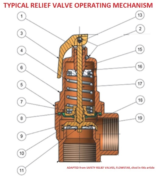
The primary purpose of a safety valve is to protect life, property and the environment. Safety valves are designed to open and release excess pressure from vessels or equipment and then close again.
The function of safety valves differs depending on the load or main type of the valve. The main types of safety valves are spring-loaded, weight-loaded and controlled safety valves.
Regardless of the type or load, safety valves are set to a specific set pressure at which the medium is discharged in a controlled manner, thus preventing overpressure of the equipment. In dependence of several parameters such as the contained medium, the set pressure is individual for each safety application.
The primary purpose of a pressure relief valve is to protect life, property and the environment. Pressure relief valves are designed to open and release excess pressure from vessels or equipment and then close again.
The function of pressure relief valves differs depending on the main type or loading principle of the valve. The main types of pressure relief valves are spring-loaded, weight-loaded and controlled pressure relief valves.
Regardless of the type or load, pressure relief valves are set to a specific set pressure at which the medium is discharged in a controlled manner, thus preventing overpressure of the equipment. In dependence of several parameters such as the contained medium, the set pressure is individual for each safety application.

(f) When operating conditions are changed, or additional boiler heating surface is installed, the valve capacity shall be increased, if necessary, to meet the new conditions and be in accordance with HG-400.l (e). The additional valves required, on account of changed conditions, may be installed on the outlet piping provided there is no intervening valve.
(a) Each hot water heating or supply boiler shall have at least one officially rated safety relief valve, of the automatic reseating type, identified with the V or HV Symbol, and set to relieve at or below the maximum allowable working pressure of the boiler.
(b) Hot water heating or supply boilers limited to a water temperature not in excess of 210°F (99°C) may have, in lieu of the valve(s) specified in (a) above, one or more officially rated temperature and pressure safety relief valves of the automatic reseating type identified with the HV symbol, and set to relieve at or below the maximum allowable working pressure of the boiler.
(c) When more than one safety relief valve is used on either hot water heating or hot water supply boilers, the additional valves shall be officially rated and may have a set pressure within a range not to exceed 6 psi (40 kPa) above the maximum allowable working pressure of the boiler up to and including 60 psi (400 kPa), and 5% for those having a maximum allowable working pressure exceeding 60 psi (400 kPa).
(d) No safety relief valve shall be smaller than NPS ¾ (DN 20) nor larger than NPS 4 (DN 100) except that boilers having a heat input not greater than 15,000 Btu/hr (4.4 kW) may be equipped with a rated safety relief valve of NPS ½ (DN 15).
(e) The required steam relieving capacity, in pounds per hour (kg/h), of the pressure relieving device or devices on a boiler shall be the greater of that determined by dividing the maximum output in Btu at the boiler nozzle obtained by the firing of any fuel for which the unit is installed by 1,000, or shall be determined on the basis of pounds (kg) of steam generated per hour per square foot (m2) of boiler heating surface as given in Table HG-400.1. For cast iron boilers constructed to the requirements of Part HC, the minimum valve capacity shall be determined by the maximum output method. In many cases a greater relieving capacity of valves will have to be provided than the minimum specified by these rules. In every case, the requirements of HG-400.2 (g) shall be met.
(f) When operating conditions are changed, or additional boiler heating surface is installed, the valve capacity shall be increased, if necessary, to meet the new conditions and shall be in accordance with HG-400,2(g). The additional valves required, on account of changed conditions, may be installed on the outlet piping provided there is no intervening valve.
(g) Safety relief valve capacity for each boiler with a single safety relief valve shall be such that, with the fuel burning equipment installed and operated at maximum capacity, the pressure cannot rise more than 10% above the maximum allowable working pressure. When more than one safety relief valve is used, the overpressure shall be limited to 10% above the set pressure of the highest set valve allowed by HG-400.2 (c).
(a)Steam to Hot Water Supply. When a hot water supply is heated indirectly by steam in a coil or pipe within the service limitations set forth in HG-101, the pressure of the steam used shall not exceed the safe working pressure of the hot water tank, and a safety relief valve at least NPS 1 (DN 25),set to relieve at or below the maximum allowable working pressure of the tank, shall be applied on the tank.
(b) High Temperature Water to Water Heat Exchanger.1 When high temperature water is circulated through the coils or tubes of a heat exchanger to warm water for space heating or hot water supply, within the service limitations set forth in HG-101, the heat exchanger shall be equipped with one or more officially rated safety relief valves that are identified with the V or HV Symbol, set to relieve at or below the maximum allowable working pressure of the heat exchanger, and of sufficient rated capacity to prevent the heat exchanger pressure from rising more than 10% above the maximum allowable working pressure of the vessel.
(c) High Temperature Water to Steam Heat Exchanger.1When high temperature water is circulated through the coils or tubes of a heat exchanger to generate low pressure steam, within the service limitations set forth in HG-101, the heat exchanger shall be equipped with one or more officially rated safety valves that are identified with the V or HV Symbol, set to relieve at a pressure not to exceed 15 psi (100 kPa), and of sufficient rated capacity to prevent the heat exchanger pressure from rising more than 5 psi (35 kPa) above the maximum allowable working pressure of the vessel. For heat exchangers requiring steam pressures greater than 15 psi (100 kPa), refer to Section I or Section VIII, Division 1.
(a) The inlet opening shall have an inside diameter approximately equal to, or greater than, the seat diameter. In no case shall the maximum opening through any part of the valve be less than ¼ in. (6 mm) in diameter or its equivalent area.
(c) O-rings or other packing devices when used on the stems of safety relief valves shall be so arranged as not to affect their operation or capacity.
(d) The design shall incorporate guiding arrangements necessary to insure consistent operation and tightness. Excessive lengths of guiding surfaces should be avoided. Bottom guided designs are not permitted on safety relief valves.
(f) Safety valves shall be spring loaded. The spring shall be designed so that the full lift spring compression shall be no greater than 80% of the nominal solid deflection. The permanent set of the spring (defined as the difference between the free height and height measured 10 min after the spring has been compressed solid three additional times after presetting at room temperature) shall not exceed 0.5% of the free height.
(h) A body drain below seat level shall be provided by the Manufacturer for all safety valves and safety relief valves, except that the body drain may be omitted when the valve seat is above the bottom of the inside diameter of the discharge piping. For valves exceeding NPS 2½ (DN 65) the drain hole or holes shall be tapped not less than NPS 3/8 (DN 10). For valves NPS 2½ (DN 65) or smaller, the drain hole shall not be less than ¼ in. (6 mm) in diameter. Body drain connections shall not be plugged during or after field installation. In safety relief valves of the diaphragm type, the space above the diaphragm shall be vented to prevent a buildup of pressure above the diaphragm. Safety relief valves of the diaphragm type shall be so designed that failure or deterioration of the diaphragm material will not impair the ability of the valve to relieve at the rated capacity.
(k) The set pressure tolerances, plus or minus, of safety valves shall not exceed 2 psi (15 kPa), and for safety relief valves shall not exceed 3 psi (20 kPa) for pressures up to and including 60 psig (400 kPa) and 5% for pressures above 60 psig (400 kPa).
(l) Safety valves shall be arranged so that they cannot be reset to relieve at a higher pressure than the maximum allowable working pressure of the boiler.
(e) Material for valve bodies and bonnets or their corresponding metallic pressure containing parts shall be listed in Section II,except that in cases where a manufacturer desires to make use of materials other than those listed in Section II, he shall establish and maintain specifications requiring equivalent control of chemical and physical properties and quality.
(a) A Manufacturer shall demonstrate to the satisfaction of an ASME designee that his manufacturing, production, and testing facilities and quality control procedures will insure close agreement between the performance of random production samples and the performance of those valves submitted for capacity certification.
(c) A Manufacturer may be granted permission to apply, the HV Code Symbol to production pressure relief valves capacity certified in accordance with HG-402.3 provided the following tests are successfully completed. This permission shall expire on the sixth anniversary of the date it is initially granted. The permission may be extended for 6 year periods if the following tests are successfully repeated within the 6 month period before expiration.
(1) Two sample production pressure relief valves of a size and capacity within the capability of an ASME accepted laboratory shall be selected by an ASME designee.
(2) Operational and capacity tests shall be conducted in the presence of an ASME designee at an ASME accepted laboratory. The valve Manufacturer shall be notified of the time of the test and may have representatives present to witness the test.
(3) Should any valve fail to relieve at or above its certified capacity or should it fail to meet performance requirements of this Section, the test shall be repeated at the rate of two replacement valves, selected in accordance with HG-401.3(c)(1), for each valve that failed.
(4) Failure of any of the replacement valves to meet the capacity or the performance requirements of this Section shall be cause for revocation within 60 days of the authorization to use the Code Symbol on that particular type of valve. During this period, the Manufacturer shall demonstrate the cause of such deficiency and the action taken to guard against future occurrence, and the requirements of HG-401.3(c) above shall apply.
(d) Safety valves shall be sealed in a manner to prevent the valve from being taken apart without breaking the seal. Safety relief valves shall be set and sealed so that they cannot be reset without breaking the seal.
(a) Every safety valve shall be tested to demonstrate its popping point, blowdown, and tightness. Every safety relief valve shall be tested to demonstrate its opening point and tightness. Safety valves shall be tested on steam or air and safety relief valves on water, steam, or air. When the blowdown is nonadjustable, the blowdown test may be performed on a sampling basis.
(c) Testing time on safety valves shall be sufficient, depending on size and design, to insure that test results are repeatable and representative of field performance.
HG-401.5 Design Requirements. At the time of the submission of valves for capacity certification, or testing in accordance with this Section, the ASME Designee has the authority to review the design for conformity with the requirements of this Section, and to reject or require modification of designs that do not conform, prior to capacity testing.
HG-402.1 Valve Markings. Each safety or safety-relief valve shall be plainly marked with the required data by the Manufacturer in such a way that the markings will not be obliterated in service. The markings shall be stamped, etched, impressed, or cast on the valve or on a nameplate, which shall be securely fastened to the valve.
(6) year built or, alternatively, a coding may be marked on the valves such that the valve Manufacturer can identify the year the valve was assembled and tested, and
HG-402.2 Authorization to Use ASME Stamp.Each safety valve to which the Code Symbol (Fig. HG-402) is to be applied shall be produced by a Manufacturer and/or Assembler who is in possession of a valid Certificate of Authorization. (See HG-540.) For all valves to be stamped with the HV Symbol, a Certified Individual (CI) shall provide oversight to ensure that the use of the “HV" Code symbol on a safety valve or safety relief valve is in accordance with this Section and that the use of the “HV" Code symbol is documented on a Certificate of Conformance Form, HV-1.
HG-402.3 Determination of Capacity to Be Stamped on Valves. The Manufacturer of the valves that are to be stamped with the Code symbol shall submit valves for testing to a place where adequate equipment and personnel are available to conduct pressure and relieving-capacity tests which shall be made in the presence of and certified by an authorized observer. The place, personnel, and authorized observer shall be approved by the Boiler and Pressure Vessel Committee. The valves shall be tested in one of the following three methods.
(a) Coefficient Method. Tests shall be made to determine the lift, popping, and blowdown pressures, and the capacity of at least three valves each of three representative sizes (a total of nine valves). Each valve of a given size shall be set at a different pressure. However, safety valves for steam boilers shall have all nine valves set at 15 psig (100 kPa). A coefficient shall be established for each test as follows:

A safety valve must always be sized and able to vent any source of steam so that the pressure within the protected apparatus cannot exceed the maximum allowable accumulated pressure (MAAP). This not only means that the valve has to be positioned correctly, but that it is also correctly set. The safety valve must then also be sized correctly, enabling it to pass the required amount of steam at the required pressure under all possible fault conditions.
Once the type of safety valve has been established, along with its set pressure and its position in the system, it is necessary to calculate the required discharge capacity of the valve. Once this is known, the required orifice area and nominal size can be determined using the manufacturer’s specifications.
In order to establish the maximum capacity required, the potential flow through all the relevant branches, upstream of the valve, need to be considered.
In applications where there is more than one possible flow path, the sizing of the safety valve becomes more complicated, as there may be a number of alternative methods of determining its size. Where more than one potential flow path exists, the following alternatives should be considered:
This choice is determined by the risk of two or more devices failing simultaneously. If there is the slightest chance that this may occur, the valve must be sized to allow the combined flows of the failed devices to be discharged. However, where the risk is negligible, cost advantages may dictate that the valve should only be sized on the highest fault flow. The choice of method ultimately lies with the company responsible for insuring the plant.
For example, consider the pressure vessel and automatic pump-trap (APT) system as shown in Figure 9.4.1. The unlikely situation is that both the APT and pressure reducing valve (PRV ‘A’) could fail simultaneously. The discharge capacity of safety valve ‘A’ would either be the fault load of the largest PRV, or alternatively, the combined fault load of both the APT and PRV ‘A’.
This document recommends that where multiple flow paths exist, any relevant safety valve should, at all times, be sized on the possibility that relevant upstream pressure control valves may fail simultaneously.
The supply pressure of this system (Figure 9.4.2) is limited by an upstream safety valve with a set pressure of 11.6 bar g. The fault flow through the PRV can be determined using the steam mass flow equation (Equation 3.21.2):
Once the fault load has been determined, it is usually sufficient to size the safety valve using the manufacturer’s capacity charts. A typical example of a capacity chart is shown in Figure 9.4.3. By knowing the required set pressure and discharge capacity, it is possible to select a suitable nominal size. In this example, the set pressure is 4 bar g and the fault flow is 953 kg/h. A DN32/50 safety valve is required with a capacity of 1 284 kg/h.
Coefficients of discharge are specific to any particular safety valve range and will be approved by the manufacturer. If the valve is independently approved, it is given a ‘certified coefficient of discharge’.
This figure is often derated by further multiplying it by a safety factor 0.9, to give a derated coefficient of discharge. Derated coefficient of discharge is termed Kdr= Kd x 0.9
Critical and sub-critical flow - the flow of gas or vapour through an orifice, such as the flow area of a safety valve, increases as the downstream pressure is decreased. This holds true until the critical pressure is reached, and critical flow is achieved. At this point, any further decrease in the downstream pressure will not result in any further increase in flow.
A relationship (called the critical pressure ratio) exists between the critical pressure and the actual relieving pressure, and, for gases flowing through safety valves, is shown by Equation 9.4.2.
Overpressure - Before sizing, the design overpressure of the valve must be established. It is not permitted to calculate the capacity of the valve at a lower overpressure than that at which the coefficient of discharge was established. It is however, permitted to use a higher overpressure (see Table 9.2.1, Module 9.2, for typical overpressure values). For DIN type full lift (Vollhub) valves, the design lift must be achieved at 5% overpressure, but for sizing purposes, an overpressure value of 10% may be used.
For liquid applications, the overpressure is 10% according to AD-Merkblatt A2, DIN 3320, TRD 421 and ASME, but for non-certified ASME valves, it is quite common for a figure of 25% to be used.
Two-phase flow - When sizing safety valves for boiling liquids (e.g. hot water) consideration must be given to vaporisation (flashing) during discharge. It is assumed that the medium is in liquid state when the safety valve is closed and that, when the safety valve opens, part of the liquid vaporises due to the drop in pressure through the safety valve. The resulting flow is referred to as two-phase flow.
The required flow area has to be calculated for the liquid and vapour components of the discharged fluid. The sum of these two areas is then used to select the appropriate orifice size from the chosen valve range. (see Example 9.4.3)


 8613371530291