
hisec safety valve free sample
A: The factory is certified with ISO9001. We are able to offer kinds of Industrial Valve based on your requirement and certified with CE, CSA, IPX7, API, UL, FM, SGS, etc.

The Supreme Court has reinforced the theory of the First Amendment as a "safety valve," reasoning that citizens who are free to to express displeasure against government through peaceful protest will be deterred from undertaking violent means. The boundary between what is peaceful and what is violent is not always clear. For example, in this 1965 photo, Alabama State College students participated in a non-violent protest for voter rights when deputies confronted them anyway, breaking up the gathering. (AP Photo/Perry Aycock, used with permission from the Associated Press)
Under the safety valve rationale, citizens are free to make statements concerning controversial societal issues to express their displeasure against government and its policies. In assuming this right, citizens will be deterred from undertaking violent means to draw attention to their causes.
The First Amendment, in safeguarding freedom of speech, religion, peaceable assembly, and a right to petition government, embodies the safety valve theory.
These and other decisions rest on the idea that it is better to allow members of the public to judge ideas for themselves and act accordingly than to have the government act as a censure. The Court has even shown support in cases concerning obscenity or speech that incites violent action. The safety valve theory suggests that such a policy is more likely to lead to civil peace than to civil disruption.
Justice Louis D. Brandeis recognized the potential for the First Amendment to serve as a safety valve in his concurring opinion in Whitney v. California (1927) when he wrote: “fear breeds repression; . . . repression breeds hate; . . . hate menaces stable government; . . . the path of safety lies in the opportunity to discuss freely supposed grievances and proposed remedies; and the fitting remedy for evil counsels is good ones.”
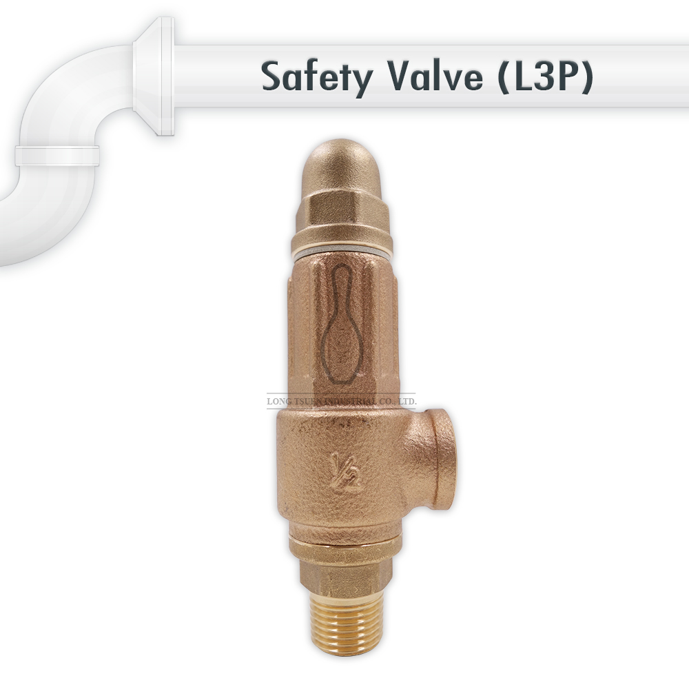
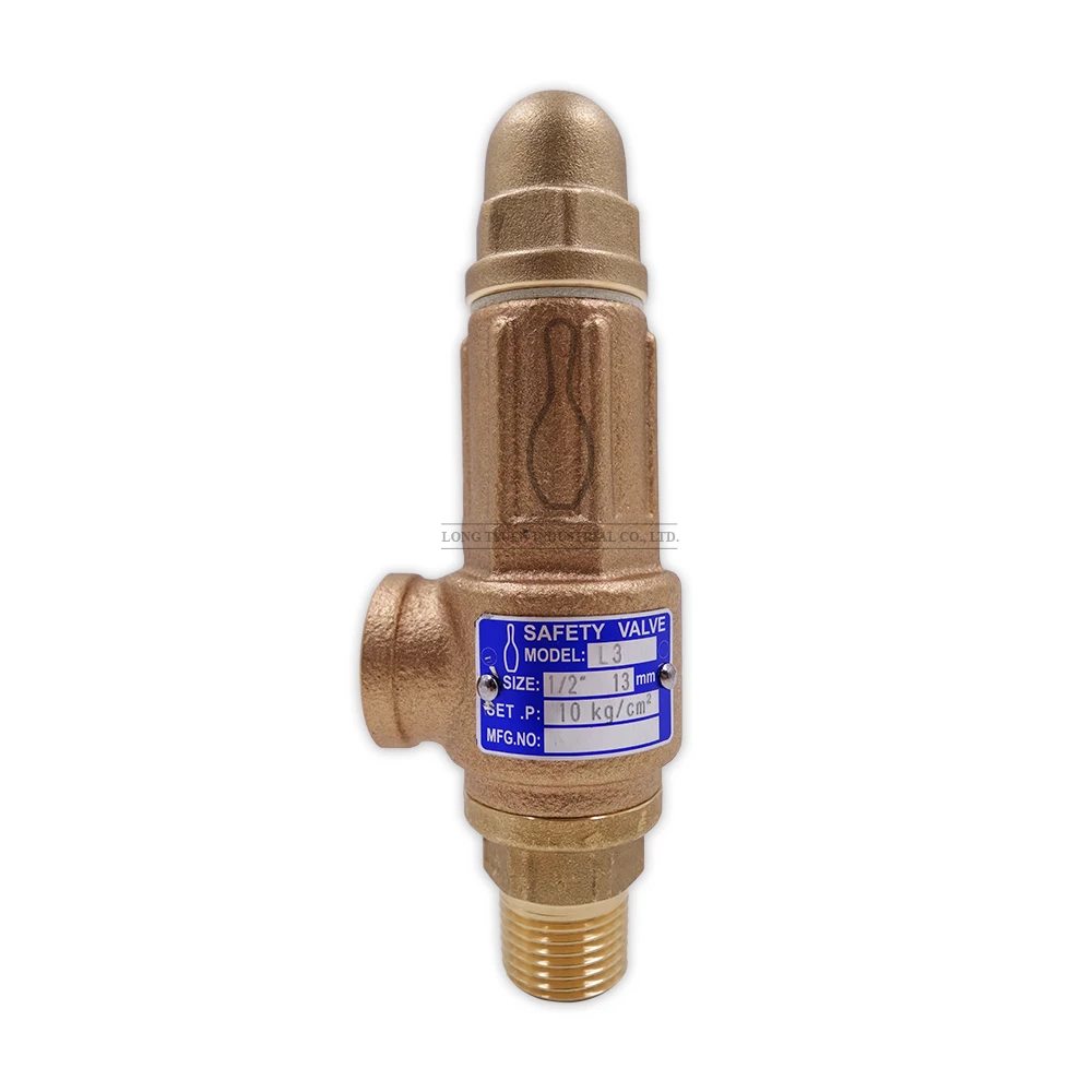
The primary purpose of a safety valve is to protect life, property and the environment. Safety valves are designed to open and release excess pressure from vessels or equipment and then close again.
The function of safety valves differs depending on the load or main type of the valve. The main types of safety valves are spring-loaded, weight-loaded and controlled safety valves.
Regardless of the type or load, safety valves are set to a specific set pressure at which the medium is discharged in a controlled manner, thus preventing overpressure of the equipment. In dependence of several parameters such as the contained medium, the set pressure is individual for each safety application.

Safety valves English safety valve is an industrial valve product, whose main function is to protect the pipeline from pressure surge beyond the rated value. During work, it is always in the closed state. When the inlet pressure exceeds the rated value, the valve opens to allow some liquid to flow through and recirculate to the container. The safety valve operates on the Bernoulli principle.
Safety valve and pressure relief valve are two types of valves with completely different features, but some people still confuse these two types of valves, so to compare the differences between them, people can follow the table below. down here.
Valve shaft: Connected to the valve disc, is a straight shaft made from high-strength materials, the main function of which is to support the opening and closing of the valve disc.
Valve body: Has a structure of an inlet and an outlet port connected to the main pipe, which is a pressure reducing pipe and an exhaust pipe to let the fluid flow to the tank. Valve body is usually made from materials such as stainless steel, copper, cast iron, steel ...
Spring: Using the elastic force of the spring to adjust the valve to open and close for pressure relief, the spring can change the compression through an adjustment screw.
Valve cover: Connected to the valve body by bolts, making the valve tight and easy to maintain, this cover is usually made of the same material as the valve body.
Adjustment screw: The adjusting screw is a part used to adjust the set pressure for the safety valve, it will directly adjust the compression of the spring.
When the pressure passing through the pipe exceeds the rated pressure to which this safety valve is preset, the pressure level of this flow exceeds the compression force of the spring. The piston will be pushed up, the safety valve is opened to discharge the fluid, excess pressure to the outside or be connected to the pipe connecting the tank to discharge to the tank. This helps to reduce the pressure.
When the pressure level in the pipeline returns to normal, the piston is pushed back to the original position, the safety valve will close completely.
Valve body: The valve body is usually made up of materials such as cast iron, copper, stainless steel, steel, etc. This valve body also has two installation ports, the inlet and outlet ports.
Auxiliary valve spring: The spring of the auxiliary valve is designed with great rigidity, which is the main part of this safety valve to adjust the set pressure of the safety valve.
Main valve spring: The spring of the main valve has a design with less stiffness than the spring of the auxiliary valve. The spring of the main valve is connected together with the piston.
Piston: A detail that closes and opens the valve"s outlet, through this part, the fluid can be discharged when overpressure or blocked when the pressure returns to normal pressure.
When the pressure in the system is below the set rating. Both the auxiliary valve and the main valve of the safety valve will be in the closed state. The higher the pressure, the greater the pressure in the upper chamber of the piston, the tighter the piston is closed (under pressure conditions below rated pressure).
When the pressure is above the rated pressure, the auxiliary valve opens, releasing the pressure in the chamber above the piston. At this time, the pressure under the piston is greater than the pressure above the piston, so the piston is pushed up, releasing the pressure in the system through the exhaust port.
When the pressure in the system returns to the pressure level below the rated pressure, the auxiliary valve closes and the main valve closes, the cycle repeats the same.
These safety valve products are mainly because of their compact, simpler design, which helps to reduce structural materials, so the cost will also be lower than indirect-acting safety valve products.
Designed with an extra valve to adjust the valve, these safety valves have a more moderate pressure release, are easier to adjust, have multiple pressure settings, and can set the rated pressure to a high level. than.
These full valves often have a more complicated structure, more details and more parts, which often makes it more difficult to maintain, service and repair the valve if the valve fails.
These indirect-acting safety valves are more suitable for clean, treated fluid applications, their auxiliary valves are often quite sensitive to dirt and are prone to clogging.
Designed with threaded connection. This type of valve is usually produced with a smaller size, with the characteristics of being compact and simple. For quick and convenient installation.
Designed with a recoil arm, which is directly linked to the valve shaft. This product will help to release pressure directly manually in case of emergency.
In the field of oil and gas, oil and gas industry, valves are used with the main purpose to discharge toxic substances to help prevent fire and explosion.
Currently, safety valves have a very diverse design, so choosing the right product for certain applications is not difficult. So, here are some tips to keep in mind:
Next, it is necessary to consider what type of system the application is (steam, gas or liquid systems). Because these fluids will have their own characteristics and valves will also have separate designs.
For example: In compressed air applications where the gas can be discharged directly to the environment, a valve with an open bonnet can be selected. For applications where liquid is discharged to the tank, or gaseous fluids are not allowed to be discharged into the environment, it is necessary to use a valve with a tight bonnet.
The structure of the valve is a factor to consider in the selection process. Valves with different structures have different characteristics and applications.
Performance is a factor to consider, valve performance requirements will vary from application to application which is why it is important to choose the right valve.
Standard requirements, safety valve standards are often concerned, because it is related to structure and performance. This standard is generally approved by independent bodies.
After determining the set pressure of the valve, we proceed to set the set pressure through the adjustment part which is the adjusting screw on the valve body.
It is necessary to flush the pipeline before installation, to avoid the accumulation of impurities and dirt that are the factors that cause damage to the details in the valve.
These valves need to be installed according to their installation standards, with different connection types the installation standards of these types will be different.
Leaks are often caused by a number of reasons such as: incorrect installation, faulty gaskets in the valve, making the valve unable to close properly. The condition of impurities and dirt mixed in the fluid can cause blockage, causing the valve to not close properly.
Failure to close or open error. The reason is that valves have discs stuck in the open position, unable to close, which causes fluid loss. Valves that do not open are discs stuck in the closed position, causing the valve to not work, which prevents the system from releasing excess pressure and endangers the system.
To prolong the life of the valve, the best way is to maintain and maintain the valve regularly and properly. Recommended maintenance period is at least once every 12 months.
A “safety valve” is an exception to mandatory minimum sentencing laws. A safety valve allows a judge to sentence a person below the mandatory minimum term if certain conditions are met. Safety valves can be broad or narrow, applying to many or few crimes (e.g., drug crimes only) or types of offenders (e.g., nonviolent offenders). They do not repeal or eliminate mandatory minimum sentences. However, safety valves save taxpayers money because they allow courts to give shorter, more appropriate prison sentences to offenders who pose less of a public safety threat. This saves our scarce taxpayer dollars and prison beds for those who are most deserving of the mandatory minimum term and present the biggest danger to society.
The Problem:Under current federal law, there is only one safety valve, and it applies only to first-time, nonviolent drug offenders whose cases did not involve guns. FAMM was instrumental in the passage of this safety valve, in 1994. Since then, more than 95,000 nonviolent drug offenders have received fairer sentences because of it, saving taxpayers billions. But it is a very narrow exception: in FY 2015, only 13 percent of all drug offenders qualified for the exception.
Mere presence of even a lawfully purchased and registered gun in a person’s home or car is enough to disqualify a nonviolent drug offender from the safety valve,
Even very minor prior infractions (e.g., careless driving) that resulted in no prison time can disqualify an otherwise worthy low-level drug offender from the safety valve, and
The Solution:Create a broader safety valve that applies to all mandatory minimum sentences, and expand the existing drug safety valve to cover more low-level offenders.

Valves for industrial applicationsIn order to prevent the uncontrolled rise in pressure in pressure vessels or pressurized pipelines, a safety valve is inserted. The safety valve is designed so that it opens at a given maximum pressure, thereby relieving the line or the container. Safety valves find their use in almost all areas of the pressure vessel and pipeline construction. In cryogenics as a spring-loaded safety valve for example.
Hisec simple steel bar 10 bar "1" is a model of safety valve (relief valve) made by Hisec company in Taiwan with a maximum working pressure of 10 bar, which is used to maintain safety in home installations such as motorhomes.
In general, safety valves are one of the most important and vital equipment in installation systems such as motorhomes and industrial sites, which open in case of a sudden increase of pressure to prevent the system from exploding and by discharging a volume of fluid (gas, air, steam or water) to Outside the system, they stabilize the pressure.
Hisec safety valves in two types of simple and simple in sizes of 1 inch, with a maximum working pressure of 10 or 20 bar made of brass or steel, are among the highest quality and at the same time the cheapest safety valves on the market for industrial applications. , Commercial or home-produced and supplied.
In the reference site and Damatajhiz store, all kinds of Hisec Asl safety valves have been provided for you, dear customers, in order to create a good feeling of optimal and smart purchase of safety valves.

A safety valve must always be sized and able to vent any source of steam so that the pressure within the protected apparatus cannot exceed the maximum allowable accumulated pressure (MAAP). This not only means that the valve has to be positioned correctly, but that it is also correctly set. The safety valve must then also be sized correctly, enabling it to pass the required amount of steam at the required pressure under all possible fault conditions.
Once the type of safety valve has been established, along with its set pressure and its position in the system, it is necessary to calculate the required discharge capacity of the valve. Once this is known, the required orifice area and nominal size can be determined using the manufacturer’s specifications.
In order to establish the maximum capacity required, the potential flow through all the relevant branches, upstream of the valve, need to be considered.
In applications where there is more than one possible flow path, the sizing of the safety valve becomes more complicated, as there may be a number of alternative methods of determining its size. Where more than one potential flow path exists, the following alternatives should be considered:
This choice is determined by the risk of two or more devices failing simultaneously. If there is the slightest chance that this may occur, the valve must be sized to allow the combined flows of the failed devices to be discharged. However, where the risk is negligible, cost advantages may dictate that the valve should only be sized on the highest fault flow. The choice of method ultimately lies with the company responsible for insuring the plant.
For example, consider the pressure vessel and automatic pump-trap (APT) system as shown in Figure 9.4.1. The unlikely situation is that both the APT and pressure reducing valve (PRV ‘A’) could fail simultaneously. The discharge capacity of safety valve ‘A’ would either be the fault load of the largest PRV, or alternatively, the combined fault load of both the APT and PRV ‘A’.
This document recommends that where multiple flow paths exist, any relevant safety valve should, at all times, be sized on the possibility that relevant upstream pressure control valves may fail simultaneously.
The supply pressure of this system (Figure 9.4.2) is limited by an upstream safety valve with a set pressure of 11.6 bar g. The fault flow through the PRV can be determined using the steam mass flow equation (Equation 3.21.2):
Once the fault load has been determined, it is usually sufficient to size the safety valve using the manufacturer’s capacity charts. A typical example of a capacity chart is shown in Figure 9.4.3. By knowing the required set pressure and discharge capacity, it is possible to select a suitable nominal size. In this example, the set pressure is 4 bar g and the fault flow is 953 kg/h. A DN32/50 safety valve is required with a capacity of 1 284 kg/h.
Coefficients of discharge are specific to any particular safety valve range and will be approved by the manufacturer. If the valve is independently approved, it is given a ‘certified coefficient of discharge’.
This figure is often derated by further multiplying it by a safety factor 0.9, to give a derated coefficient of discharge. Derated coefficient of discharge is termed Kdr= Kd x 0.9
Critical and sub-critical flow - the flow of gas or vapour through an orifice, such as the flow area of a safety valve, increases as the downstream pressure is decreased. This holds true until the critical pressure is reached, and critical flow is achieved. At this point, any further decrease in the downstream pressure will not result in any further increase in flow.
A relationship (called the critical pressure ratio) exists between the critical pressure and the actual relieving pressure, and, for gases flowing through safety valves, is shown by Equation 9.4.2.
Overpressure - Before sizing, the design overpressure of the valve must be established. It is not permitted to calculate the capacity of the valve at a lower overpressure than that at which the coefficient of discharge was established. It is however, permitted to use a higher overpressure (see Table 9.2.1, Module 9.2, for typical overpressure values). For DIN type full lift (Vollhub) valves, the design lift must be achieved at 5% overpressure, but for sizing purposes, an overpressure value of 10% may be used.
For liquid applications, the overpressure is 10% according to AD-Merkblatt A2, DIN 3320, TRD 421 and ASME, but for non-certified ASME valves, it is quite common for a figure of 25% to be used.
Two-phase flow - When sizing safety valves for boiling liquids (e.g. hot water) consideration must be given to vaporisation (flashing) during discharge. It is assumed that the medium is in liquid state when the safety valve is closed and that, when the safety valve opens, part of the liquid vaporises due to the drop in pressure through the safety valve. The resulting flow is referred to as two-phase flow.
The required flow area has to be calculated for the liquid and vapour components of the discharged fluid. The sum of these two areas is then used to select the appropriate orifice size from the chosen valve range. (see Example 9.4.3)


 8613371530291