
hot water safety valve free sample

Air conditioning heat pump pressure bypass valves are important in any air conditioning system. These valves help regulate the amount of refrigerant sent through an AC system and help keep it running smoothly and efficiently. Without these valves, the system would be unable to operate properly, causing a wide range of problems from decreased efficiency to total system failure. Here we will provide a brief overview of how AC heat pump pressure bypass valves work, their advantages, and why they are so important for your AC system.
The most common type of pressure bypass valve is a fixed-orifice design. This type consists of two ports – one port allows the refrigerant to pass through while the other directs high-pressure liquid away from the compressor.
A pressure bypass valve is an important component of an air conditioning heat pump system. It helps to prevent excessive high-pressure buildup, thus ensuring that your system operates efficiently and safely. Pressure bypass valves are most commonly found in split systems, as they control the refrigerant flow.
The main purpose of a pressure bypass valve is to protect the air conditioning compressor from being damaged due to excessive pressure build-up. Allowing excess liquid refrigerant to bypass the compressor helps reduce the risk of damage caused by overpressurization. It also prevents the liquid refrigerant from entering other components within the system and causing further damage. The valve is typically installed at either end of a heat pump’s evaporator coil, with both ends connected via pipes or hoses.
A pressure bypass valve is a critical component of an air conditioning heat pump system. It is designed to control refrigerant flow in the system, allowing it to be safely regulated and maintained. The valve helps to maintain a safe level of pressure within the system and prevents damage from occurring due to excessively high-pressure levels.
The operation of a pressure bypass valve is relatively simple. When the system’s temperature increases, causing the refrigerant pressure to rise, it triggers the valve to open and allows some of that pressure to escape. This reduces the overall pressure to maintain a safe operating level, allowing optimal performance and efficiency. When temperatures drop again, and lower pressures are reached, the valve will close back up automatically until needed.
As homeowners look for ways to lower their energy bills and maintain their air conditioning systems, they should consider the advantages of an air conditioning heat pump pressure bypass valve. This device helps keep the system running smoothly and can reduce costly repairs due to its ability to regulate high-pressure conditions.
The pressure bypass valve is designed to open when system pressures become too high. This prevents damage by allowing refrigerant gas or liquid to flow into another location in a controlled manner. As the refrigerant flows through the valve, it equalizes temperatures between indoor and outdoor units, increasing efficiency while lowering operating costs.
Pressure bypass valves are essential to the air conditioning and heat pump system. They help regulate the pressure within the system, ensuring it works correctly and safely. However, like all mechanical components, pressure bypass valves can experience common issues that may require attention from a qualified HVAC technician.
The most common problem with pressure bypass valves is clogging or sticking due to debris buildup in the valve itself. This can cause airflow restriction, reducing efficiency and increasing energy costs for homeowners. In addition, if dirt or other contaminants enter the valve housing, it can cause an imbalance in pressure levels leading to potential leaks within the system. Other less frequent issues include malfunctioning solenoids or damaged O-rings, which will require replacement parts for repair.
Are you looking for an easy way to install a pressure bypass valve? Installing an air conditioning heat pump pressure bypass valve can be tricky, but understanding the process and having the right tools can make it easier. Keep reading to learn more about installation tips for pressure bypass valves that will help make your project successful.
When installing a pressure bypass valve, it is important to ensure you have all the necessary components before beginning. This includes any mounting hardware, such as screws or brackets, tubing and clamps, and the correct size O-rings. Additionally, you’ll need a wrench set, screwdriver set, wire cutters, adjustable pipe wrench, and tubing bender. Once you’ve gathered all of these items together, check your manufacturer’s instructions for specific installation and setup procedures details.
The air conditioning heat pump pressure bypass valve is an important part of any air conditioning system. As such, it is important to understand the benefits and considerations of having one installed in a residential or commercial space.
One of the major advantages of having a pressure bypass valve installed is that it helps keep the system running efficiently. By preventing over-pressurization, the valve ensures proper operation and prevents costly repairs or downtime due to malfunction. Additionally, it helps protect against water damage should there be a sudden change in pressure levels in the system, which can help reduce overall maintenance costs.
However, like any other system component, some considerations are associated with installing a pressure bypass valve. These include ensuring proper installation by qualified personnel to ensure safe operation and regularly inspecting and maintaining the device for optimal performance.

BSP/NPT connection Pressure safety relief valves are typically used to control pressure on boilers in heating systems, on stored hot water cylinders in domestic hot water systems, and generally in water systems.
When the calibrated pressure is reached, the valve opens and, using discharge to the atmosphere, prevents the pressure of the system from reaching levels that would be dangerous for the boiler and the components in the system itself.
The brass safety relief valve is a piece of equipment found in industrial settings. The valve has two functions: release pressure and protect against over-pressure situations. These valves are designed for steam, water, gas, or other liquids that may expand when removed from the pipe. They can be found on boilers and pressure vessels such as pipelines; they will often be placed at an elevation high enough above the ground so that a rupture won’t cause any damage. These valves have many features.
Brass Safety Relief Valve with DN15 NPT female inlet and 1/2″ male outlet. This is a great safety valve for water tanks. It has a 200 PSI pressure rating, making it perfect to work with your tank!
This product is designed to work for water tanks. It has a brass body, which makes it durable and sturdy. The safety relief valve helps prevent damage caused by excessive pressure build-up in the tank during use. It is easy to install and can be used with any water tank.
The Brass Safety Relief Valve is designed for use in water tanks, as it has a 2″ female NPT connection. The valve features a solid brass body and bonnet, which can withstand high temperatures of up to 200°F (93°C). This relief valve also features a 1/2″ male NPT connection that can be used with the discharge hose.
The Brass Safety Relief Valve should be installed on the bottom or side of your water tank. You will need to drill an opening in your tank to install this safety device.
Brass Safety Relief Valve is a type of safety valve that prevents the tank from over-pressurization. The brass safety relief valve has a spring-loaded poppet that opens when the pressure in the tank rises above a predetermined value. It can be installed on water tanks, boilers, and other pressure vessels.
1) Brass Safety Relief Valve is easy to install, with no need for flanges or welding. It can be mounted in any position and does not require the pipework to seal off the rest of the system.
The Brass Safety Relief Valve is a safety device to prevent the over-pressurization of water tanks and piping. The valve closes when the pressure reaches a certain level, preventing damage to the equipment. It also prevents flooding and allows for easy maintenance by opening when needed. This brass relief valve is designed for hot and cold water and fire sprinkler systems. Operating at a temperature range of -40 degrees F to 180 degrees F, it can be used in residential or commercial settings.

Temperature/pressure-relief or TPR valves are safety devices installed on water heating appliances, such as boilers and domestic water supply heaters. TPRs are designed to automatically release water in the event that pressure or temperature in the water tank exceeds safe levels.
If temperature sensors and safety devices such as TPRs malfunction, water in the system may become superheated (exceed the boiling point). Once the tank ruptures and water is exposed to the atmosphere, it will expand into steam almost instantly and occupy approximately 1,600 times its original volume. This process can propel a heating tank like a rocket through multiple floors, causing personal injury and extensive property damage.
Water-heating appliance explosions are rare due to the fact that they require a simultaneous combination of unusual conditions and failure of redundant safety components. These conditions only result from extreme negligence and the use of outdated or malfunctioning equipment.
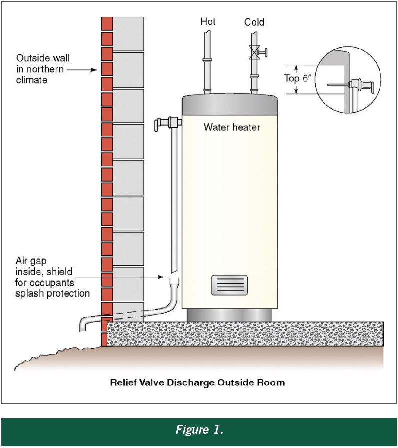
The TPR valve will activate if either water temperature (measured in degrees Fahrenheit) or pressure (measured in pounds per square inch [PSI]) exceed safe levels. The valve should be connected to a discharge pipe (also called a drain line) that runs down the length of the water heater tank. This pipe is responsible for routing hot water released from the TPR to a proper discharge location.
It is critical that discharge pipes meet the following requirements, which can be found in InterNACHI’s Water Heater Discharge Piping mini-course, at www.nachi.org/education. A discharge pipe should:
be first piped to an indirect waste receptor such as a bucket through an air gap located in a heated area when discharging to the outdoors in areas subject to freezing, since freezing water could block the pipe.
A properly functioning TPR valve will eject a powerful jet of hot water from the discharge pipe when fully activated, not a gentle leak. A leaky TPR valve is an indication that it needs to be replaced. In the rare case that the TPR valve does activate, the homeowner should immediately shut off the water and contact a qualified plumber for assistance and repair.
Inspectors should recommend that homeowners test TPR valves monthly, although inspectors should never do this themselves. The inspector should demonstrate to the homeowner how the main water supply can be shut off, and explain that it can be located at the home"s main water supply valve, or at the water supply shut-off for the appliance on which the TPR is mounted.
The pressure at which a TPR valve will activate is printed on a data plate located beneath the test lever. This amount should not exceed the working pressure limit marked on the data plate of the water-heating appliance it serves.
TPR valves with missing data plates should be replaced.Although a TPR valve might never become activated, it is an essential safety component on boilers and domestic water heaters. Guidelines concerning these valves and their discharge pipes reflect real hazards that every homeowner and home inspector should take seriously. More information about this subject can be found in InterNACHI"s Water Heater Discharge Piping mini-course, InterNACHI"s Plumbing Inspection course or by contacting a qualified plumber.
A safety valve must always be sized and able to vent any source of steam so that the pressure within the protected apparatus cannot exceed the maximum allowable accumulated pressure (MAAP). This not only means that the valve has to be positioned correctly, but that it is also correctly set. The safety valve must then also be sized correctly, enabling it to pass the required amount of steam at the required pressure under all possible fault conditions.
Once the type of safety valve has been established, along with its set pressure and its position in the system, it is necessary to calculate the required discharge capacity of the valve. Once this is known, the required orifice area and nominal size can be determined using the manufacturer’s specifications.
In order to establish the maximum capacity required, the potential flow through all the relevant branches, upstream of the valve, need to be considered.
In applications where there is more than one possible flow path, the sizing of the safety valve becomes more complicated, as there may be a number of alternative methods of determining its size. Where more than one potential flow path exists, the following alternatives should be considered:
This choice is determined by the risk of two or more devices failing simultaneously. If there is the slightest chance that this may occur, the valve must be sized to allow the combined flows of the failed devices to be discharged. However, where the risk is negligible, cost advantages may dictate that the valve should only be sized on the highest fault flow. The choice of method ultimately lies with the company responsible for insuring the plant.
For example, consider the pressure vessel and automatic pump-trap (APT) system as shown in Figure 9.4.1. The unlikely situation is that both the APT and pressure reducing valve (PRV ‘A’) could fail simultaneously. The discharge capacity of safety valve ‘A’ would either be the fault load of the largest PRV, or alternatively, the combined fault load of both the APT and PRV ‘A’.
This document recommends that where multiple flow paths exist, any relevant safety valve should, at all times, be sized on the possibility that relevant upstream pressure control valves may fail simultaneously.
The supply pressure of this system (Figure 9.4.2) is limited by an upstream safety valve with a set pressure of 11.6 bar g. The fault flow through the PRV can be determined using the steam mass flow equation (Equation 3.21.2):
Once the fault load has been determined, it is usually sufficient to size the safety valve using the manufacturer’s capacity charts. A typical example of a capacity chart is shown in Figure 9.4.3. By knowing the required set pressure and discharge capacity, it is possible to select a suitable nominal size. In this example, the set pressure is 4 bar g and the fault flow is 953 kg/h. A DN32/50 safety valve is required with a capacity of 1 284 kg/h.
Coefficients of discharge are specific to any particular safety valve range and will be approved by the manufacturer. If the valve is independently approved, it is given a ‘certified coefficient of discharge’.
This figure is often derated by further multiplying it by a safety factor 0.9, to give a derated coefficient of discharge. Derated coefficient of discharge is termed Kdr= Kd x 0.9
Critical and sub-critical flow - the flow of gas or vapour through an orifice, such as the flow area of a safety valve, increases as the downstream pressure is decreased. This holds true until the critical pressure is reached, and critical flow is achieved. At this point, any further decrease in the downstream pressure will not result in any further increase in flow.
A relationship (called the critical pressure ratio) exists between the critical pressure and the actual relieving pressure, and, for gases flowing through safety valves, is shown by Equation 9.4.2.
Overpressure - Before sizing, the design overpressure of the valve must be established. It is not permitted to calculate the capacity of the valve at a lower overpressure than that at which the coefficient of discharge was established. It is however, permitted to use a higher overpressure (see Table 9.2.1, Module 9.2, for typical overpressure values). For DIN type full lift (Vollhub) valves, the design lift must be achieved at 5% overpressure, but for sizing purposes, an overpressure value of 10% may be used.
For liquid applications, the overpressure is 10% according to AD-Merkblatt A2, DIN 3320, TRD 421 and ASME, but for non-certified ASME valves, it is quite common for a figure of 25% to be used.
Two-phase flow - When sizing safety valves for boiling liquids (e.g. hot water) consideration must be given to vaporisation (flashing) during discharge. It is assumed that the medium is in liquid state when the safety valve is closed and that, when the safety valve opens, part of the liquid vaporises due to the drop in pressure through the safety valve. The resulting flow is referred to as two-phase flow.
The required flow area has to be calculated for the liquid and vapour components of the discharged fluid. The sum of these two areas is then used to select the appropriate orifice size from the chosen valve range. (see Example 9.4.3)
Year after year, your water heater serves an important role in your home. Your morning routine just wouldn’t be the same—or nearly as comfortable—without hot water. Yet, water heaters and their components do not last forever. Preventative maintenance is the key to ensuring that your water heater continues to safely provide your home with hot water. In this article, we’ll review a critical safety component of your water heater, the water heater pressure-relief valve.
If your water heater has stopped working, fill out the form to schedule a free VIP plumbing inspection here in the Chicago area. Our plumbers are available 24/7 to help you and your home!
The name is actually quite literal. It’s a valve that relieves excess pressure in the water heater tank. By doing so, it can prevent excess pressure buildup that has the potential to cause a tank burst and flood your home. It’s an unheralded but essential safety mechanism for your water heater.
As your water heater heats up the water in the tank, the water expands and steam is generated. The greater the heat, the more expansion that occurs. This expansion puts pressure on the exterior walls of the tank, but this is to be expected. Some degree of excess pressure escapes through the water pipes connected to the water heater. In the event that it cannot, the pressure-relief valve triggers. By releasing some of the hot water and air, the valve lowers the pressure back down to safe levels.
If the pressure-relief valve is unable to open, the pressure can continue to build inside of the tank past that 100 PSI ceiling. The heavy metal tank can withstand a lot of pressure buildup, but it eventually has its limits. The results are explosive, as the tank gives way, sending hot water flooding outward.
If your water heater has an emergency shutoff valve installed, the burst will be detected and the water supply will automatically shutoff. If not, you’re potentially looking at a flooded home with significant and costly water damage.
So, what causes the pressure-relief valve to fail? In many cases, the valve gets stuck or frozen in place due to the buildup of rust and corrosion inside the tank. Or, the valve is stuck due to a prior instance in which it released hot water.
A broken valve is something that should be fixed right away, but—unless you’re examining your water heater closely on a regular basis—may not be something most homeowners notice. That’s why regular testing and maintenance is important.
We recommend that homeowners here in Chicago test their pressure-relief valve when they flush out their water heater twice every year. Bundling your water heater maintenance tasks together makes sense, since each of these tasks takes about 10 minutes to complete.
Start by positioning a large bucket underneath the valve. You are going to release some hot water during this process, so you want to make sure you’re wearing safe clothes to reduce a scalding risk. Remove the drain pipe attached to the pressure valve.
Then, gently lift the valve switch so that hot water begins to come out of the valve and into the bucket. For the purposes of this test, don’t push the switch all the way up.
So long as water and air are coming out of the water heater during this test, your water heater pressure-relief valve is working as intended. On the other hand, if you’ve flipped the switch up and you’re not seeing any release, that could indicate a problem with the valve.
Did you know that most people use between 80 and 100 gallons of water every day? From using the restroom and showering to cooking and cleaning, your water usage is a crucial part of your daily home routine. Here are just a few daily tasks most homeowners do without thinking, and the corresponding amount of water it takes to complete them: Flushing a toilet: 1-3 gallons per flush
This doesn’t take into account washing your hands, taking a bath, or watering your lawn. Your water use may also skyrocket during the summer, when you’re drinking more water or cooling off in the sprinklers.
Taking all this into account, it’s crucial that your water systems are working at their full capacity. Your water heater delivers hot water to your home, and your water pressure needs to be sufficient for your appliances to work and for your showers to be comfortable.
For all your daily tasks to run smoothly, water pressure is especially important. Imagine not having enough water pressure to flush a toilet or take a shower. There are other consequences to having water pressure that is too high.
To get your water pressure checked and adjusted by a professional, call the team at King Heating, Cooling, & Plumbing in Chicago, Illinois. We’re the experts on all home systems and can make sure your home is running at 100% capacity.
It’s been a long day at work, and you want to come home, take a hot shower, and relax with the family. You turn on the shower to see a small stream of water—or droplets—coming from the shower head. Even when you turn the shower handle to full capacity, only a small amount of water drips out. What’s the problem?
Your water pressure is likely too low. This can be an annoying setback for many homeowners, who depend on high water pressure to shower, clean, cook, and more. How can you properly shower or wash your hands when only a few drops are coming out of the faucet?
On the opposite side of the water pressure spectrum, high water pressure can pose a danger to you and your family inside the home. When water pressure is too high, pipes can become damaged and systems can overwork themselves to bring that water to you. It’s just like the tale of Goldilocks and the Three Bears: you don’t want your water pressure too low or too high—you want it just right.
Low water pressure is usually just a nuisance to homeowners and doesn’t pose a serious problem. High water pressure, on the other hand, can damage fixtures, seals, joints, and more. Water pressure that’s too high can also waste a lot of water in the home, leaving you with a higher utility bill at the end of the month.
As it comes from the municipal water supply to your home, residential water generally ranges from 40 to 80 PSI (pounds per square inch). Anything above or below this range could be considered too low or too high. Some experts will say that any level above 60 PSI is too high of water pressure for your home. It’s best to speak with a professional plumber to get your water pressure checked and to learn more about what level is right for your home. Your PSI range can be affected by elevation, house size, water needs, age of your home, and other factors.
If you haven’t checked your water pressure level in a while, it may be time to call King for a free VIP plumbing inspection. Even if you feel your water pressure and water heater are working great, there could be hidden efficiency problems lurking underneath the surface, such as a water heater that is running too hot and wasting energy. Only a true plumbing professional can get to the bottom of the issue and help you save money, month-over-month.
This goes without saying, but if you’re not comfortable flushing your water heater or checking the valve, don’t just ignore this crucial maintenance need. Give our team a call and have us out to your home to perform this service for you. Remember, this preventative maintenance can help prevent a tank burst and major water damage.
The location of a water heater is always a concern. Many are installed inside a living space and tucked away in a closet. It doesn’t take much imagination to envision what could happen when one of these water heaters is not installed properly. A water heater temperature and pressure relief valve is an important safety device for water heaters as well as the water distribution system to which it is connected. A new edition of CodeNotes—Water Heater Safety in the I-Codes (based on the 2018 IPC and IRC) — provides an understanding of the detailed requirements on these items from an overall safety viewpoint.
There are other important items associated with the relief valve. These items are mentioned in Section 504.6 of the International Plumbing Code (IPC) and Section P2804.6.1 of the International Residential Code (IRC). These sections address the requirements of discharge piping serving a pressure relief valve, temperature relief valve or combination temperature and pressure relief valve. Because the discharge piping from these safety devices that serve water heaters are an extension of the potable water distribution system, the outlet of the discharge pipe must be treated as a potable water supply system outlet.
Item 3 requires the discharge piping not be smaller than the diameter of the outlet of the valve served and must discharge full size to the air gap. (See Figure 2)
Item 4 requires the discharge piping serve only a single relief device and that it shall not connect to piping serving any other relief device or equipment. Figure 3 illustrates an approved means of connecting the discharge from multiple water heater relief valves. The code is silent as to the size or shape of the waste receptors and the gravity drain line size for capturing and conveying the discharge water from relief valves.
Item 6 requires the discharge piping to discharge in a manner that does not cause personal injury or structural damage. A good example of locations that are not suitable for the termination of relief valve drain lines are shower floors, laundry trays, kitchen sinks, and bath tub. Anyone that would be using these fixtures could be subject to injury by hot water and steam that could come from the pipes.
Item 7 requires the discharge to terminate to a point that is readily observable by the building occupants. It is important that the occupant be aware of the discharging relief valve or valves as soon as possible to limit the amount of discharge that may possibly cause damage or injury.
Items 8 and 9 require the relief valve discharge line to not be trapped and must drain by gravity without sags in the piping. Retained water in these trapped areas or piping sags might cause a buildup of scale or corrosion over time, or possibly freeze if the piping is located in an area that is subject to freezing. Both situations have the potential to create a blockage to any discharge that might come from a relief valve which would create a dangerous condition.
Item 10 requires the relief valve to terminate no more than 6 inches (152mm) above the floor surface, a waste receptor or floor drain in order to prevent hot water discharge from being directed onto a building occupant that may be nearby. Obviously for termination points to the floor, the floor must be a suitable location for water discharge or a floor drain or waste receptor must be provided to capture and direct discharges from the pipe. See Figure 5 for example of approved and unapproved termination.
Item 11 requires the discharge piping have no threaded connection at the end of such piping. This would make it easy for someone to screw on a cap or valve to stop the dripping water from the pipe. What might be perceived as an easy repair by the handy person could create a dangerous situation that could result in severe damage of the building and injury or death of the occupants. (See Figure 6)
Item 12 prohibits discharge pipes from having valves or tees installed. The valve and tee fittings are obviously prohibited as the valve can be closed creating a dangerous situation and the tee fitting could allow connections of piping from other sources. (See Figure 7)
To summarize, the installation requirements of discharge piping serving a pressure relief valve, temperature relief valve or combination temperature and pressure relief valve mentioned in Section P2804.6.1 of the IRC and Section 504.6 of the IPC are extremely important. If not installed as required by this code could result in contamination of the potable water supply system and or create a very dangerous situation that could result in explosion.
As part of its goal to serve the needs of plumbing, mechanical and fuel gas (PMG) officials, the ICC PMG Official Membership Council is committed to providing free, informative code support documents known as CodesNotes that can be used to complement building departments’ in-house weekly supplemental training. We hope you enjoy this newest edition of CodeNotes. Past topics include backflow devices and the protection of the water supply, gas pipe sizing based on the latest edition of the International Fuel Gas Code and the International Residential Code, and bonding of corrugated stainless steel tubing gas piping systems, just to name a few. The CodesNotes collection has recently been expanded to include a selection of notes offered in Spanish.

(a) Each steam boiler shall have one or more officially rated safety valves that are identified with the V or HV Symbol of the spring pop type adjusted and sealed to discharge at a pressure not to exceed 15 psi (100 kPa).
(b) No safety valve for a steam boiler shall be smaller than NPS ½ (DN 15) or larger than NPS 4 (DN 100). The inlet opening shall have an inside diameter equal to, or greater than, the seat diameter.
(d) The minimum valve capacity in pounds per hour shall be the greater of that determined by dividing the maximum Btu output at the boiler nozzle obtained by the firing of any fuel for which the unit is installed by 1,000, or shall be determined on the basis of the pounds (kg) of steam generated per hour per square foot (m2)of boiler heating surface as given in Table HG-400.1. For cast iron boilers constructed to the requirements of Part HC, the minimum valve capacity shall be determined by the maximum output method. In many cases a greater relieving capacity of valves will have to be provided than the minimum specified by these rules. In every case, the requirement of HG-400.l(e) shall be met.
(e) The safety valve capacity for each steam boiler shall be such that with the fuel burning equipment installed, and operated at maximum capacity, the pressure cannot rise more than 5 psi (35 Kpa) above the maximum allowable working pressure.
(f) When operating conditions are changed, or additional boiler heating surface is installed, the valve capacity shall be increased, if necessary, to meet the new conditions and be in accordance with HG-400.l (e). The additional valves required, on account of changed conditions, may be installed on the outlet piping provided there is no intervening valve.
(a) Each hot water heating or supply boiler shall have at least one officially rated safety relief valve, of the automatic reseating type, identified with the V or HV Symbol, and set to relieve at or below the maximum allowable working pressure of the boiler.
(b) Hot water heating or supply boilers limited to a water temperature not in excess of 210°F (99°C) may have, in lieu of the valve(s) specified in (a) above, one or more officially rated temperature and pressure safety relief valves of the automatic reseating type identified with the HV symbol, and set to relieve at or below the maximum allowable working pressure of the boiler.
(c) When more than one safety relief valve is used on either hot water heating or hot water supply boilers, the additional valves shall be officially rated and may have a set pressure within a range not to exceed 6 psi (40 kPa) above the maximum allowable working pressure of the boiler up to and including 60 psi (400 kPa), and 5% for those having a maximum allowable working pressure exceeding 60 psi (400 kPa).
(d) No safety relief valve shall be smaller than NPS ¾ (DN 20) nor larger than NPS 4 (DN 100) except that boilers having a heat input not greater than 15,000 Btu/hr (4.4 kW) may be equipped with a rated safety relief valve of NPS ½ (DN 15).
(e) The required steam relieving capacity, in pounds per hour (kg/h), of the pressure relieving device or devices on a boiler shall be the greater of that determined by dividing the maximum output in Btu at the boiler nozzle obtained by the firing of any fuel for which the unit is installed by 1,000, or shall be determined on the basis of pounds (kg) of steam generated per hour per square foot (m2) of boiler heating surface as given in Table HG-400.1. For cast iron boilers constructed to the requirements of Part HC, the minimum valve capacity shall be determined by the maximum output method. In many cases a greater relieving capacity of valves will have to be provided than the minimum specified by these rules. In every case, the requirements of HG-400.2 (g) shall be met.
(f) When operating conditions are changed, or additional boiler heating surface is installed, the valve capacity shall be increased, if necessary, to meet the new conditions and shall be in accordance with HG-400,2(g). The additional valves required, on account of changed conditions, may be installed on the outlet piping provided there is no intervening valve.
(g) Safety relief valve capacity for each boiler with a single safety relief valve shall be such that, with the fuel burning equipment installed and operated at maximum capacity, the pressure cannot rise more than 10% above the maximum allowable working pressure. When more than one safety relief valve is used, the overpressure shall be limited to 10% above the set pressure of the highest set valve allowed by HG-400.2 (c).
(a)Steam to Hot Water Supply. When a hot water supply is heated indirectly by steam in a coil or pipe within the service limitations set forth in HG-101, the pressure of the steam used shall not exceed the safe working pressure of the hot water tank, and a safety relief valve at least NPS 1 (DN 25),set to relieve at or below the maximum allowable working pressure of the tank, shall be applied on the tank.
(b) High Temperature Water to Water Heat Exchanger.1 When high temperature water is circulated through the coils or tubes of a heat exchanger to warm water for space heating or hot water supply, within the service limitations set forth in HG-101, the heat exchanger shall be equipped with one or more officially rated safety relief valves that are identified with the V or HV Symbol, set to relieve at or below the maximum allowable working pressure of the heat exchanger, and of sufficient rated capacity to prevent the heat exchanger pressure from rising more than 10% above the maximum allowable working pressure of the vessel.
(c) High Temperature Water to Steam Heat Exchanger.1When high temperature water is circulated through the coils or tubes of a heat exchanger to generate low pressure steam, within the service limitations set forth in HG-101, the heat exchanger shall be equipped with one or more officially rated safety valves that are identified with the V or HV Symbol, set to relieve at a pressure not to exceed 15 psi (100 kPa), and of sufficient rated capacity to prevent the heat exchanger pressure from rising more than 5 psi (35 kPa) above the maximum allowable working pressure of the vessel. For heat exchangers requiring steam pressures greater than 15 psi (100 kPa), refer to Section I or Section VIII, Division 1.
(a) The inlet opening shall have an inside diameter approximately equal to, or greater than, the seat diameter. In no case shall the maximum opening through any part of the valve be less than ¼ in. (6 mm) in diameter or its equivalent area.
(c) O-rings or other packing devices when used on the stems of safety relief valves shall be so arranged as not to affect their operation or capacity.
(d) The design shall incorporate guiding arrangements necessary to insure consistent operation and tightness. Excessive lengths of guiding surfaces should be avoided. Bottom guided designs are not permitted on safety relief valves.
(f) Safety valves shall be spring loaded. The spring shall be designed so that the full lift spring compression shall be no greater than 80% of the nominal solid deflection. The permanent set of the spring (defined as the difference between the free height and height measured 10 min after the spring has been compressed solid three additional times after presetting at room temperature) shall not exceed 0.5% of the free height.
(h) A body drain below seat level shall be provided by the Manufacturer for all safety valves and safety relief valves, except that the body drain may be omitted when the valve seat is above the bottom of the inside diameter of the discharge piping. For valves exceeding NPS 2½ (DN 65) the drain hole or holes shall be tapped not less than NPS 3/8 (DN 10). For valves NPS 2½ (DN 65) or smaller, the drain hole shall not be less than ¼ in. (6 mm) in diameter. Body drain connections shall not be plugged during or after field installation. In safety relief valves of the diaphragm type, the space above the diaphragm shall be vented to prevent a buildup of pressure above the diaphragm. Safety relief valves of the diaphragm type shall be so designed that failure or deterioration of the diaphragm material will not impair the ability of the valve to relieve at the rated capacity.
(k) The set pressure tolerances, plus or minus, of safety valves shall not exceed 2 psi (15 kPa), and for safety relief valves shall not exceed 3 psi (20 kPa) for pressures up to and including 60 psig (400 kPa) and 5% for pressures above 60 psig (400 kPa).
(l) Safety valves shall be arranged so that they cannot be reset to relieve at a higher pressure than the maximum allowable working pressure of the boiler.
(e) Material for valve bodies and bonnets or their corresponding metallic pressure containing parts shall be listed in Section II,except that in cases where a manufacturer desires to make use of materials other than those listed in Section II, he shall establish and maintain specifications requiring equivalent control of chemical and physical properties and quality.
(a) A Manufacturer shall demonstrate to the satisfaction of an ASME designee that his manufacturing, production, and testing facilities and quality control procedures will insure close agreement between the performance of random production samples and the performance of those valves submitted for capacity certification.
(c) A Manufacturer may be granted permission to apply, the HV Code Symbol to production pressure relief valves capacity certified in accordance with HG-402.3 provided the following tests are successfully completed. This permission shall expire on the sixth anniversary of the date it is initially granted. The permission may be extended for 6 year periods if the following tests are successfully repeated within the 6 month period before expiration.
(1) Two sample production pressure relief valves of a size and capacity within the capability of an ASME accepted laboratory shall be selected by an ASME designee.
(2) Operational and capacity tests shall be conducted in the presence of an ASME designee at an ASME accepted laboratory. The valve Manufacturer shall be notified of the time of the test and may have representatives present to witness the test.
(3) Should any valve fail to relieve at or above its certified capacity or should it fail to meet performance requirements of this Section, the test shall be repeated at the rate of two replacement valves, selected in accordance with HG-401.3(c)(1), for each valve that failed.
(4) Failure of any of the replacement valves to meet the capacity or the performance requirements of this Section shall be cause for revocation within 60 days of the authorization to use the Code Symbol on that particular type of valve. During this period, the Manufacturer shall demonstrate the cause of such deficiency and the action taken to guard against future occurrence, and the requirements of HG-401.3(c) above shall apply.
(d) Safety valves shall be sealed in a manner to prevent the valve from being taken apart without breaking the seal. Safety relief valves shall be set and sealed so that they cannot be reset without breaking the seal.
(a) Every safety valve shall be tested to demonstrate its popping point, blowdown, and tightness. Every safety relief valve shall be tested to demonstrate its opening point and tightness. Safety valves shall be tested on steam or air and safety relief valves on water, steam, or air. When the blowdown is nonadjustable, the blowdown test may be performed on a sampling basis.
(c) Testing time on safety valves shall be sufficient, depending on size and design, to insure that test results are repeatable and representative of field performance.
HG-401.5 Design Requirements. At the time of the submission of valves for capacity certification, or testing in accordance with this Section, the ASME Designee has the authority to review the design for conformity with the requirements of this Section, and to reject or require modification of designs that do not conform, prior to capacity testing.
HG-402.1 Valve Markings. Each safety or safety-relief valve shall be plainly marked with the required data by the Manufacturer in such a way that the markings will not be obliterated in service. The markings shall be stamped, etched, impressed, or cast on the valve or on a nameplate, which shall be securely fastened to the valve.
(6) year built or, alternatively, a coding may be marked on the valves such that the valve Manufacturer can identify the year the valve was assembled and tested, and
HG-402.2 Authorization to Use ASME Stamp.Each safety valve to which the Code Symbol (Fig. HG-402) is to be applied shall be produced by a Manufacturer and/or Assembler who is in possession of a valid Certificate of Authorization. (See HG-540.) For all valves to be stamped with the HV Symbol, a Certified Individual (CI) shall provide oversight to ensure that the use of the “HV" Code symbol on a safety valve or safety relief valve is in accordance with this Section and that the use of the “HV" Code symbol is documented on a Certificate of Conformance Form, HV-1.
“The society which scorns excellence in plumbing as a humble activity and tolerates shoddiness in philosophy because it is an exalted activity will have neither good plumbing nor good philosophy: neither its pipes nor its theories will hold water.”
Plumbing may be defined as the practice, materials, and fixtures used in installing, maintaining, and altering piping, fixtures, appliances, and appurtenances in connection with sanitary or storm drainage facilities, a venting system, and public or private water supply systems. Plumbing does not include drilling water wells; installing water softening equipment; or manufacturing or selling plumbing fixtures, appliances, equipment, or hardware. A plumbing system consists of three parts: an adequate potable water supply system; a safe, adequate drainage system; and ample fixtures and equipment.
The housing inspector’s prime concern while inspecting plumbing is to ensure the provision of a safe water supply system, an adequate drainage system, and ample and proper fixtures and equipment that do not contaminate water. The inspector must make sure that the system moves waste safely from the home and protects the occupants from backup of waste and dangerous gases. This chapter covers the major features of a residential plumbing system and the basic plumbing terms and principles the inspector must know and understand to identify housing code violations that involve plumbing. It will also assist in identifying the more complicated defects that the inspector should refer to the appropriate agencies. This chapter is not a plumbing code, but should provide a base of knowledge sufficient to evaluate household systems.
The piping of a house service line should be as short as possible. Elbows and bends should be kept to a minimum because they reduce water pressure and, therefore, the supply of water to fixtures in the house. The house service line also should be protected from freezing. Four feet of soil is a commonly accepted depth to bury the line to prevent freezing. This depth varies, however, across the country from north to south. The local or state plumbing code should be consulted for recommended depths. The minimum service line size should be ¾ inch. The minimum water supply pressure should be 40 pounds per square inch (psi), no cement or concrete joints should be allowed, no glue joints between different types of plastic should be allowed, and no female threaded PVC fittings should be used.
Corporation stop—The corporation stop is connected to the water main. This connection is usually made of brass and can be connected to the main with a special tool without shutting off the municipal supply. The valve incorporated in the corporation stop permits the pressure to be maintained in the main while the service to the building is completed.
Curb stop—The curb stop is a similar valve used to isolate the building from the main for repairs, nonpayment, of water bills or flooded basements. Because the corporation stop is usually under the street and it is necessary to break the pavement to reach the valve, the curb stop is used as the isolation valve.
Curb stop box—The curb stop box is an access box to the curb stop for opening and closing the valve. A long-handled wrench is used to reach the valve.
Meter stop—The meter stop is a valve placed on the street side of the water meter to isolate it for installation or maintenance. Many codes require a gate valve on the house side of the meter to shut off water for plumbing repairs. The curb and meter stops can be ruined in a short time if used very frequently.
The water meter is a device used to measure the amount of water used in the house. It is usually the property of the water provider and is a very delicate instrument that should not be abused. In cold climates, the water meter is often inside the home to keep it from freezing. When the meter is located inside the home, the company providing the water must make appointments to read the meter, which often results in higher water costs unless the meter is equipped with a signal that can be observed from the outside. The water meter is not shown in
Because the electric system is sometimes grounded to an older home’s water line, a grounding loop device should be installed around the meter. Many meters come with a yoke that maintains electrical continuity even though the meter is removed.
The hot and cold water main lines are usually hung from the basement ceiling or in the crawl space of the home and are attached to the water meter and hot water tank on one side and the fixture supply risers on the other. These pipes should be installed neatly and should be supported by pipe hangers or straps of sufficient strength and number to prevent sagging. Older homes that have copper pipe with soldered pipes can pose a lead poisoning risk, particularly to children. In 1986, Congress banned lead solder containing greater than 0.2% lead and restricted the lead content of faucets, pipes, and other plumbing materials to no more than 8%. The water should be tested to determine the presence or level of lead in the water. Until such tests can be conducted, the water should be run for about 2 minutes in the morning to flush any such material from the line. Hot and cold water lines should be approximately 6 inches apart unless the hot water line is insulated. This is to ensure that the cold water line does not pick up heat from the hot water line [2].
The supply mains should have a drain valve stop and waste valve to remove water from the system for repairs. These valves should be on the low end of the line or on the end of each fixture riser.
The size of basement mains and risers depends on the number of fixtures supplied. However, a ¾-inch pipe is usually the minimum size used. This allows for deposits on the pipe due to hardness in the water and will usually give satisfactory volume and pressure.
In homes without basements, the water lines are preferably located in the crawl space or under the slab. The water lines are sometimes placed in the attic; however, because of freezing, condensation, or leaks, this placement can result in major water damage to the home. In two-story or multistory homes, the water line placement for the second floor is typically between the studs and, then, for the shortest distance to the fixture, between the joists of the upper floors.
Care must be taken when choosing the piping materials. Some state and local plumbing codes prohibit using some of the materials listed below in water distribution systems.
Polyvinyl Chloride (PVC). PVC is used to make plastic pipe. PVC piping has several applications in and around homes such as in underground sprinkler systems, piping for swimming pool pumping systems, and low-pressure drain systems PVC piping is also used for water service between the meter and building [3]. PVC, or polyvinyl chloride, is one of the most commonly used materials in the marketplace. It is in packaging, construction and automotive material, toys, and medical equipment.
Chlorinated PVC. CPVC is a slightly yellow plastic pipe used inside homes. It has a long service life, but is not quite as tough as copper. Some areas with corrosive water will benefit by using chlorinated PVC piping. CPVC piping is designed and recommended for use in hot and cold potable water distribution systems [4].
Copper lasts a long time, is durable, and connects well to valves. It should not be installed if the water has a pH of 6.5 or less. Most public utilities supply water at a pH between 7.2 and 8.0. Many utilities that have source water with a pH below 6.5 treat the water to raise the pH. Private well water systems often have a pH below 6.5. When this is the case, installing a treatment system to make the water less acidic is a good idea [5].
Galvanized Steel. Galvanized pipe corrodes rather easily. The typical life of this piping is about 40 years. One of the primary problems with galvanized steel is that, in saturated water, the pipe will become severely restricted by corrosion that eventually fills the pipe completely. Another problem is that the mismatch of metals between the brass valves and the steel results in corrosion. Whenever steel pipe meets copper or brass, the steel pipe will rapidly corrode. Dielectric unions can be used between copper and steel pipes; however, these unions will close off flow in a short time. The problem with dielectric unions is that they break the grounding effect if a live electrical wire comes in contact with a pipe. Some cities require the two pipes to be bonded electrically to maintain the safety of grounded pipes.
PEX is flexible and can be installed with fewer fittings than rigid plumbing systems. It is a good choice for repiping and for new homes and works well for corrosive water conditions. PEX stretches to accommodate the expansion of freezing water and then returns to its original size when water thaws. Although it is highly freeze-resistant, no material is freeze-proof.
Poly. Poly pipe is a soft plastic pipe that comes in coils and is used for cold water. It can crack with age or wear through from rocks. Other weak points can be the stainless steel clamps or galvanized couplings.
In the United States, more than 112,000 people enter a hospital emergency room each year with scald burns. Of these, 6,700 (6%), have to be hospitalized. Almost 3,000 of these scald burns come from tap water in the home. The three high risk groups are children under the age of 5 years, the handicapped, and adults over the age of 65 years. It only takes 1 second to get a serious third-degree burn from water that is 156ºF (69ºC). Tap water is too hot if instant coffee granules melt in it.
Young children, some handicapped individuals, and elderly people are particularly vulnerable to tap water burns. Children cannot always tell the hot water faucets from the cold water faucets. Children have delicate skin and often cannot get out of hot water quickly, so they suffer hot water burns most frequently. Elderly and handicapped persons are less agile and more prone to falls in the bath tub. They also may have diseases, such as diabetes, that make them unable to feel heat in some regions of the body, such as the hands and feet. Third-degree burns can occur quickly—in 1 second at 156ºF (69ºC), in 2 seconds at 149ºF (65ºC), in 5 seconds at 140ºF (60ºC), and in 15 seconds at 133ºF (56ºC).
A tap-water temperature of 120ºF–130ºF (49ºC–54ºC) is hot enough for washing clothes, bedding, and dishes. Even at 130ºF (54ºC), water takes only a few minutes of constant contact to produce a third-degree burn. Few people bathe at temperatures above 110ºF (43ºC), nor should they. Water heater thermostats should be set at about 120ºF (49ºC) for safety and to save 18% of the energy used at 140ºF (60ºC). Antiscald devices for faucets and showerheads to regulate water temperature can help prevent burns. A plumber should install and calibrate these devices. Most hot water tank installations now require an expansion tank to reduce pressure fluctuations and a heat trap to keep hot water from escaping up pipes.
It is essential that valves be used in a water system to allow the system to be controlled in a safe and efficient manner. The number, type, and size of valves required will depend on the size and complexity of the system. Most valves can be purchased in sizes and types to match the pipe sizes used in water system installations. Listed below are some of the more commonly encountered valves with a description of their basic functions.
Shutoff Valves. Shutoff valves should be installed between the pump and the pressure tank and between the pressure tank and service entry to a building. Globe, gate, and ball valves are common shutoff valves. Gate and ball valves cause less friction loss than do globe valves; ball valves last longer and leak less than do gate valves. Shutoff valves allow servicing of parts of the system without draining the entire system.
Flow-control Valves. Flow-control valves provide uniform flow at varying pressures. They are sometimes needed to regulate or limit the use of water because of limited water flow from low-yielding wells or an inadequate pumping system. They also may be needed with some treatment equipment. These valves are often used to limit flow to a fixture. Orifices, mechanical valves, or diaphragm valves are used to restrict the flow to any one service line or complete system and to assure a minimum flow rate to all outlets.
Relief Valves. Relief valves permit water or air to escape from the system to relieve excess pressure. They are spring-controlled and are usually adjustable to relieve varying pressures, generally above 60 psi. Relief valves should be installed in systems that may develop pressures exceeding the rated limits of the pressure tank or distribution system. Positive displacement and submersible pumps and water heaters can develop these excessive pressures. The relief valve should be installed between the pump and the first shutoff valve and must be capable of discharging the flow rate of the pump. A combined pressure and temperature relief valve is needed on all water heaters. Combination pressure and vacuum relief valves also should be installed to prevent vacuum damage to the system.
Pressure-reducing Valves. A pressure-reducing valve is used to reduce line pressure. On main lines, this allows the use of thinner walled pipe and protects house plumbing. Sometimes these valves are installed on individual services to protect plumbing.
Altitude Valves. Often an altitude valve is installed at the base of a hot water tank to prevent it from overflowing. Altitude valves sense the tank level through a pressure line to the tank. An adjustable spring allows setting the level so that the valve closes and prevents more inflow when the tank becomes full.
Foot Valves. A foot valve is a special type of check valve installed at the end of a suction pipe or below the jet in a well to prevent backflow and loss of prime. The valve should be of good quality and cause little friction loss.
Check Valves. Check valves have a function similar to foot valves. They permit water flow in only one direction through a pipe. A submersible pump may use several check valves. One is located at the top of the pump to prevent backflow from causing back spin of the impellers. Some systems use another check valve and a snifter valve. They will be in the drop pipe or pitless unit in the well casing and allow a weep hole located between the two valves to drain part of the pipe. When the pump is started, it will force the air from the drained part of the pipe into the pressure tank, thus recharging the pressure tank.
Frost-proof Faucets. Frost-proof faucets are installed outside a house with the shutoff valve extending into the heated house to prevent freezing. After each use, the water between the valve and outlet drains, provided the hose is disconnected, so water is not left to freeze.
Frost-proof Hydrants. Frost-proof hydrants make outdoor water service possible during cold weather without the danger of freezing. The shutoff valve is buried below the frost line. To avoid submerging it, which might result in contamination and back siphoning, the stop-and-waste valve must drain freely into a rock bed. These hydrants are sometimes prohibited by local or state health authorities.
Miscellaneous Switches. Float switches respond to a high and/or low water level as with an intermediate storage tank. Pressure switches with a low-pressure cutoff stop the pump motor if the line pressure drops to the cutoff point. Low-flow cutoff switches are used with submersible pumps to stop the pump if the water discharge falls below a predetermined minimum operating pressure. High-pressure cut-off switches are used to stop pumps if the system pressure rises above a predetermined maximum. Paddle-type flow switches detect flow by means of a paddle placed in the pipe that operates a mechanical switch when flow in the pipe pushes the paddle.
The inadvertent contamination of a public water supply as a result of incorrectly installing plumbing fixtures is a potential public health problem in all communities. Continuous surveillance by environmental health personnel is necessary to know whether such public health hazards have developed as a result of additions or alterations to an approved system. All environmental health specialists should learn to recognize the three general types of defects found in potable water supply systems: backflow, back siphonage, and overhead leakage into open potable water containers. If identified, these conditions should be corrected immediately to prevent the spread of disease or poisoning from high concentrations of organic or inorganic chemicals in the water.
A properly installed T&P valve will operate when either the temperature or the pressure becomes too high due to an interruption of the water supply or a faulty thermostat.
Water heaters that are installed on wooden floors should have water collection pans with a drainage tube that drains to a proper drain. The pan should be checked on a regular basis.
A tankless unit has a heating device that is activated by the flow of water when a hot water valve is opened. Once activated, the heater delivers a constant supply of hot water. The output of the heater, however, limits the rate of the heated water flow. Demand water heaters are available in propane (LP), natural gas, or electric models. They come in a variety of sizes for different applications, such as a whole-house water heater, a hot water source for a remote bathroom or hot tub, or as a boiler to provide hot water for a home heating system. They can also be used as a booster for dishwashers, washing machines, and a solar or wood-fired domestic hot water system [7].
The appeal of demand water heaters is not only the elimination of the tank standby losses and the resulting lower operating costs, but also the fact that the heater delivers hot water continuously. Most tankless models have a life expectancy of more than 20 years. In contrast, storage tank water heaters last 10 to 15 years. Most tankless models have easily replaceable parts that can extend their life by many years more.
Water is brought into a house, used, and discharged through the drainage system. This system is a sanitary drainage system carrying just interior wastewater.
Size of House Drain. The Uniform Plumbing Code Committee has developed a method of sizing house drains in terms of fixture units. One fixture unit equals approximately 7½ gallons of water per minute. This is the surge flow rate of water discharged from a wash basin in one minute. All other fixtures have been related to this unit. Fixture unit values are shown in
As mentioned earlier, the purpose of a trap is to seal out sewer gases from the structure. Because a plumbing system is subject to wide variations in flow, and this flow originates in many different sections of the system, pressures vary widely in the waste lines. These pressure differences tend to remove the water seal in the trap. The waste system must be properly vented to prevent the traps from siphoning dry, thus losing their water seal and allowing gas from the sewer into the building.
If a waste pipe is placed vertically after the fixture trap, as in an S-trap, the wastewater continues to flow after the fixture is emptied and clears the trap. This is caused by the pressure of air on the water of the fixture being greater than the pressure of air in the waste pipe. The action of the water discharging into the waste pipe removes the air from that pipe and thereby causes a negative pressure in the waste line.
In the case of indirect or momentum siphonage, the flow of water past the entrance to a fi


 8613371530291