
how does a gas safety valve work manufacturer

Most modern appliances have safety features built in, but your gas oven safety valve is arguably the most important. If an electrical appliance malfunctions, it can cause a fire, but a misfiring gas oven could potentially blow up your house. You don"t really need to know how the safety mechanism works to use your oven, but you may find that it gives you some extra peace of mind.
Broadly speaking, there are two ways a built-in safety mechanism can work. One option is that it remains "open" by default and to shut off if certain conditions are met. That"s how fuses and circuit breakers work in an electrical circuit: Ordinarily, the electricity is free to flow, but if the current grows too large, the fuse or breaker will blow and cut off the circulation of electricity.
The other option is for your safety mechanism to be "closed" by default and allow a device to operate only when the correct conditions are met. That"s how a gas oven safety valve works. Gas ordinarily is prevented from flowing, and if the valve is working correctly, it opens only when you want to light your oven.
Many gas stoves use what"s called a "hot surface igniter," a bar or element (similar to the ones on your stovetop) that gets hot enough to ignite the gas on contact. Gas oven safety valves on stoves with this type of ignition system take a couple of different approaches.
In one approach, a bimetallic strip operates the valve. It harnesses a simple scientific principle: Metals expand and contract at different rates when they"re heated and cooled. If you bond two suitable metals together in one strip, that strip will flex to a predictable degree as the temperature goes up and down. Wall-mount thermostats often use this principle, as do analog oven thermometers and the thermometer in the lid of your gas grill.
As appliance-repair website PartSelect explains, turning on your gas oven causes electricity to flow into the heating element of your hot surface igniter. As the igniter heats up, it warms a bimetallic strip inside your gas oven safety valve. When the igniter reaches its operating temperature, the bimetallic strip opens the valve and allows the gas to flow, igniting as it crosses the heated surface.
One intriguing thing about electricity is that a change in temperature can affect how well it passes through certain materials. For example, a lot of research revolves around superconductors – materials that offer very little resistance to an electrical current – but superconductors typically must be heavily chilled to work.
According to heating-equipment vendor Anglo Nordic, gas oven safety valves use a variation of that principle to operate. In these stoves, the flow of electrical current through the hot surface igniter becomes the control mechanism. The igniter"s bar is made of a material that offers less and less resistance to electricity as it heats. When it reaches the temperature required to ignite the gas, its resistance becomes low enough to trip the safety valve and open the flow of gas.
More modern ranges use an electrical igniter. When you turn on your oven, the gas begins flowing immediately, and it sends an electrical current to a piezo electric igniter. The current makes the igniter spark (like the manual igniter on your gas grill) and lights the oven"s burner. In this case, the safety valve works in the opposite way: An electronic sensor checks for the heat caused by ignition after a few seconds, and if it"s absent, it will close the valve and shut off the flow of gas.
It"s worth pointing out that not all gas ovens have a safety valve in the conventional sense. Older stoves simply use a pilot light, a small but constant flow of gas, which, in turn, feeds a small, candle-like flame. You essentially are the safety mechanism in this system: It"s up to you to check that the pilot is lit. When you turn on the gas manually, the small pilot flame ignites the main flame. It"s a mechanically simple system, which makes it durable, and for that reason, you"ll still see it used on commercial restaurant ranges, which must stand up to decades of heavy use.
First developed for use on early steam boilers as operating without them would cause an explosion unless carefully operated. Modern burner ovens now feature a gas safety valve to prevent an explosion when unlit. Unless ignited by an electric glow bar, pilot flame or electric spark with a gas supply, the valve will remain closed.
Safety should be you’re top priority when you’re working with gas. If you’re not careful, its extremely easy to cause a lot of damage. To prevent this modern day gas safety valves have been fitted around the world, to ensure an efficiently working system.
When your gas safety valves are on their last legs, making a repair or finding a replacement is the best thing to do. Keeping a spare in your kit is highly recommended.
The glow bar igniter and safety valve are wired in series within a glow bar system. This means that electricity can only pass through the valve after it has first passed through the glow bar. Electrical resistance from the glow bar blocks current to the gas valve, making sure that the valve closes. This decreases as the temperature increases. When the bar reaches a particular heat, enough to ignite the gas, it allows sufficient electricity through to open the gas valve.
The gas ignition source on Pilot light ignition system uses a low flame, fed by a line from the thermostat. The pilot flame will either burn constantly or be ignited electronically when the oven is switched on. More gas is fed to the pilot flame when the oven thermostat wants heat. Either excess pressure or an electric current will open the gas valve.
With some ovens the burner is directly ignited with an electric spark. An electric spark is sent to ignite the burner when the gas valve opens, this is due to the thermostat wanting heat. A sensor on the burner detects the flame and confirms ignition. The oven burner will lock out if there is no ignition after two attempts.
Pressure relief valves are usually installed in multi appliance, oil pumped ringmain systems. They are used to maintain a constant pressure on the positive side of the pump whether all appliances are in use or not.
Safety relief discharge pressurised gases and vapours to protect against overpressure. This is done by discharging pressurised gases and vapours from pipelines, this includes pressure vessels and plant components. Safety relief valves are the last line of defence and prevent explosion which could be fatal.
These spring-loaded and direct-acting. When the opening pressure is reached, valve gives way and opens, releasing the pressure. The pressures then equalised and the automatically closes.
Relief valves can either discharge into atmosphere, or via a connected blow-off line. The opening pressure of the boiler relief valve valve is preset usually at the factory according to the customer’s requirements.
Anglo Nordic have just what you need! If you have any questions for need more information, simply call us on 0208 979 0988 or email us at sales@anglo-nordic.com
A furnace gas valve is a component of your furnace’s fuel system. The furnace gas valve opens and closes, which allows the flow of gas to the pilot light and burner(s). While the component itself if actually rather simple, a furnace gas valve is a crucial part of your HVAC system. Furnace gas valves are only seen on gas-fueled forced air furnaces or gas-powered boilers. There are also gas valves located within gas-powered hot water systems or fireplaces.
There are essentially two valves that make up your furnace’s gas valve, and they are positioned in series, or one after the other. The furnace gas valve operates by electromagnets. The primary valve -- also known as the safety valve -- supplies gas to the pilot light. The second valve -- also known as the main valve -- allows gas to flow to the burner trays.
The thermocouple (or thermopile) generates the power holds the safety valve open. Additionally, the thermocouple remains immersed in the pilot light flame. Without adequate heating of the thermocouple or thermopile, the furnace gas valve closes. As a result, this cuts off the supply of gas to the pilot light. Ultimately, the thermocouple acts as a safety mechanism that prevents gas buildup within the home.
A 24 VAC transformer (or the thermopile) powers the main valve. This valve allows gas to flow to the burner trays via a much larger tube than the pilot light valve. Additionally, the valves are installed in series with all of the other furnace safety controls. As a result, if the system detects a problem, then the circuit interrupts itself. During this process, the system shuts off power to the main furnace gas valve, while still keeping the pilot light valve open.
As the thermostat calls for heat, the furnace gas valve opens and closes. This process maintains the desired temperature within the home. Plus, this design helps regulate the pressure of gas flowing into the furnace.
There are a few types of furnace gas valve systems: gas chain, consisting of a manual valve, solenoid valve, and pilot safety; and a combination gas valve. A gas chain valve system requires the homeowner to manually turn a valve handle in order to open or close the flow of gas to the furnace. A solenoid valve opens only when the furnace calls for heat. As a result, gas only flows if all the other valves in the system are open. Plus, the pilot safety valve only stays open if the thermocouple or thermopile heats to a certain temperature by the pilot flame. It can be manually overridden in order to relight the pilot light, but otherwise operates via electromagnets as described above.
The combination gas valve gained popularity in the 1960s and performs all the functions of the gas chain in one package. It contains a valve knob or handle, regulator, thermocouple, electric terminals, and a solenoid valve. As technology has progressed, combination gas valves have fallen out of regular use, with their job now being performed by electronic ignition controls or integrated furnace controls (IFCs).
If you think your furnace gas valve is not working, there are a couple of steps you can take to troubleshoot the problem and narrow down the root cause.
Check to see if the pilot light is on. If not, follow the manufacturer’s instructions for relighting the pilot light. It may take a few seconds after relighting the pilot light for the main valve to have enough power to stay open.
Check to see if the thermocouple or thermopile is generating enough voltage to keep the safety valve open. If not, you can replace it. Also check to ensure the other safety mechanisms within the circuit are receiving adequate voltage. If this doesn’t fix the problem, you will need to replace the entire furnace gas valve.
If you need to replace the gas valve in your furnace, costs will vary depending on the make and model, as well as your location as labor costs differ depending on region and even season.
Although many homeowners troubleshoot heating issues, the best option remains consultation with a qualified HVAC professional if your furnace isn’t operating properly. They are experts who can get your heat back up and running quickly and safely.

As a design engineer responsible for developing and specifying boilers, dryers, furnaces, heaters, ovens and other industrial heating equipment, you face a daunting labyrinth of standards and industry regulations. Regulatory bodies sound a bit like alphabet soup, with acronyms like UL, FM, CSA, UR, AGA, ASME, ANSI, IRI, CE and NFPA tossed about. This article will help explain a common task for many thermal processing equipment specifiers: meeting the requirements of key codes — including Underwriters Laboratories (UL), Factory Mutual Insurers (FM) and the National Fire Protection Association (NFPA) — for safety valve equipment used in process heating applications.
Key to designing safety into your fuel train configurations are familiar technologies such as safety shutoff valves and vent valves as well as visual-indication mechanisms and proof-of-closure switches.
Your design skills come into play with how you take advantage of the wide range of products available. You can mix and match solenoid and safety shutoff valves — within designs from catalytic reactors to multi-zone furnaces — to create easily installed, cost-effective solutions that comply with all necessary standards. (See table.)
Make sure, however, that you start with a good grasp of valve element fundamentals. For example, examining a proof-of-closure (POC) switch underlines how reliably modern valves can ensure combustion safety. The POC unit provides an electrical contact interlocked with the controller safety circuit. In a typical design, the switch is located at the bottom of the valve, positioned to trace the stroke of the valve disc. When the disc seal reaches the fully closed position, it triggers the mechanism to push down on the contact, closing it and triggering the unit’s visual indicator to show open or closed status. As a result, the operator can act with full confidence in situations where it is critical that a safety valve be safely closed.
To provide ease of installation, many users prefer valves with modular capabilities. For example, to reduce mounting complexity, you can choose modular gas safety shut-off valves — combining a solenoid valve with an electrohydraulic motorized valve for a compact double-valve footprint, a slow-open feature and high flow rates. An accompanying actuator can provide on/off or high/low/off firing rates as well as visual indication and proof of closure for compliance with most industry standards.
Also, you may want to look for valves that include useful features such as pipe taps, which can facilitate accurate pressure readings and leakage testing.
Knowing your valve choices — and how they meet given codes and standards — can reduce the time required for design and production while facilitating compliance. This results in safer, more efficient and cost-effective heating process installations.

If you have been searching for a safety release valve that you can use to reduce short-term pressure surges successfully and diminish the effects of gas leaks, this is the product for ...
... regulators have safety valves which will slam shut in the event of emergencies, such as the gas reaching too high a pressure level. The valve works to protect any fittings ...
This product has hydraulically actuated class A gas safety valves to EN 161 used for automatic shut-off. It shuts off when unstimulated for gas and air, ...
The S 104 Safety Shut Off valve is mainly used to avoid any damage to components as well as to avoid too high or too low pressure in the gas train. This could cause high financial losses ...
The S50 Safety Shut Off valve is mainly used to avoid any damage to components as well as to avoid too high or too low pressure in the gas train. This could cause high financial losses ...
The S100 Safety Shut Off valve is mainly used to avoid any damage to components as well as to avoid too high or too low pressure in the gas train. This could cause high financial losses ...
... Pressure Safety Valve + Rupture Disk is protected and may be utilized autonomously as essential security gadgets or in conjunction. There are 3 possible combinations. The first combinations ...
It"s a Safety valve in according with Directives ATEX 20K/34/EU. Technical Norm Fire Prevention 41/256 31/10/2019. d.P.R. 10/520 19/03/1955 and subsequent amendments.
This range of spring loaded conventional and balanced safety relief valves is specifically designed for overpressure protection of unfired pressure vessel (ASME Section VIII application). ...
130 Series Safety valves are also available as Relief valves. Relief valves, identified by the letter R after the type number, are devices with an operational function, ...
V651 Series safety relief valves are produced as safety and relief type. Safety valves are pressure relief elements used to evacuate excessive pressure ...
PVS type slam shut valves are pilot-operated relief valves in which the opening and the closing of the main plug is controlled by a pilot device which is very ...
The EMERSON BM7 SERIES is a disk slam-shut valve characterized as automatic isolating elements, which are suitable for installation as safety devices in regulating stations. This device has a high operation ...
... control and regulate the gas, air flow to burners and other combustion devices. HMV is a unique safety valve that can be supplied for the requiremen of handling higher ...
Type 50 is a safety valve for universal use. It can be used for nearly any industrial application, e.g. in shipping and pipeline construction, the chemical and petrochemical industries, ...
The RIEGER Safety valve Type SH prevents excessive pressure in steam and gaseous media in plant components and tanks. The set pressure is generally higher than the operating pressure of the system.
... sewage, gas, glycol, diathermic oil, industrial water, steam and other natural and aggressive media, depending on theresistance of materials usedfor the construction ofthe valve.
With DirectIndustry you can: Find the product, subcontractor or service provider you need | Find a nearby distributor or reseller| Contact the manufacturer to get a quote or a price | Examine product characteristics and technical specifications for major brands | View PDF catalogues and other online documentation

As a crucial component of combustion safety, fuel safety shutoff valves must be specified correctly and have proven reliability. Industry Standards, Approvals and other considerations unique to these applications can be impactful on engineering specification and vendor/supplier selection. Misinformation relative to the specific requirements associated with the fuel safety shutoff applications can lead to regulatory pitfalls as well as compromised safety.
Note: A “Safety Shutoff Valve” is defined by Factory Mutual as “a normally closed or normally open valve and actuator assembly that automatically returns to normal position in response to a remote safety shutdown signal, loss of actuating medium, or under the influence of heat. Normally open safety shutoff valves are sometimes referred to as vent valves as defined in ASME CSD-1-2012, Controls and Safety Devices for Automatically Fired Boilers.”
The specification, testing and maintenance of fuel safety shutoff valves (typically abbreviated as SSV’s or SSoV’s) involve particular considerations which are recognized within North American industry standards, such as Factory Mutual (FM) Global Class 7400 (fire safe class 7440), or CSA International Standards Specification Z21.21/CSA 6.5 Automated Valves For Gas Appliances, and CGA3.9-M94 Automated Safety Shut Off Gas Valves. Additionally, National Fire Protection Association standards for combustion safety such as NFPA 85 for Boiler and Combustion Systems, NFPA 86 Standard for Ovens and Furnaces, and NFPA 87 Standard for Fluid Heaters, emphasize the use of listed or “approved” valves – manufacturers who have received formal approval by FM or CSA for specifically constructed assemblies that meet the standards stated above. FM Approved “Heat Activated Safety Shutoff Valves” and “Supervisory Cock Valves”, associated with FM Class 7422, also have application in some combustion systems, the details for which are outside the scope of this document.
Not all combustion systems are regarded as an OSHA Process Safety Management (PSM) covered process. OSHA has issued interpretations of 29 CFR 1910.119(a)(1)(ii)(A) which is sometimes referred to as the “fuels exemption”. This essentially means that fuels used in combustion systems which are not part of a process containing another highly hazardous chemical are not subject to the OSHA Process Safety Management requirements.
However, many combustion systems, especially in the hydrocarbon processing industry, would involve a “covered” process. While the specific implications are appropriately left to the reader, The U.S. Occupational Safety and Health Administration released a Memorandum in June of 2015 to provide guidance “on the enforcement of the Process Safety Management (PSM) Standard’s recognized and generally accepted good engineering practices (RAGAGEP) requirements, including how to interpret “shall” and “should” language in published codes, standards, published technical reports, recommended practices (RP) or similar documents…” This was updated by OSHA in May of 2016 with the PSM standard also emphasizing that inspections and tests are to be performed on process equipment (equipment in a PSM covered process or associated with hazard prevention), subject to the standard’s mechanical integrity requirements and in accordance with manufacturer recommendations.
OSHA specifically refers to provisions noted in consensus documents as “shall” in regards to RAGAGEP which would be considered for violation by OSHA if a deviation occurs, and OSHA is emphasizing the importance of following industry codes, standards and recommended practice, such as the NFPA documents referenced above for combustion related hazards.
Note: NFPA 85 Section 5.1.3 states: “All safety shutoff valves, safety interlock devices, valve proving systems, and flame detection systems shall be listed or approved. A safety shutoff valve proof of closure switch shall be an original design component of the valve or actuator assembly and shall activate only after the valve is fully closed.”
In addition, a review of publicly available OSHA investigative records reveals several accidents related to combustion systems, which were not PSM covered processes. Should a hazardous incident occur, the follow up investigation and analysis can include an evaluation of whether recognized and applicable engineering practices, codes and/or standards were originally followed in design, testing and maintenance, with accordant liability implications.
FM Class Number 7400 details what is necessary to achieve approval, which sets performance requirements for liquid and gas safety shutoff valves used in commercial and industrial fuel supply lines to burners and ignitable liquid piping systems. A few of the more notable FM approval facts and requirements are detailed below:
Factory Mutual must satisfactorily evaluate the product and manufacturer, including the specific assemblies offered for approval. The process is sufficiently rigorous and not without appreciable cost for the manufacturer. The number of automated valve assembly manufacturers which have qualified for FM approval is limited.
Revisions in approved assembly construction are not allowed without proposed changes being vetted by Factory Mutual. To retain FM approval, field repair must be completed by an FM approved entity.
FM evaluation includes an examination of manufacturer facilities and quality control execution with regular periodic audits required for continued approval status.
FM Approved SSV’s will have certification marks, applied by the manufacturer, as authorized by FM Approvals, along with other required tag information.
Valve position indication must be visible from at least five feet. The failure of an electrically operated valve indicator cannot imply an incorrect position. However, these requirements are waived for solenoid valves up to ¾” NPT in size/connection.
Overtravel of the actuator stem is required if an electrically operated valve indicator (limit switch) is used as an interlock in a combustion safety circuit.
Operating temperature range of the assembly must be at least 32F to 140F. This is verified in sample assembly leakage testing at min and max temperatures.
Upon loss of holding medium (typically, electricity or air), the SSV must return to normal position within 5 seconds or less under all applicable process conditions for the rated working pressure. This includes multiple tests at various inlet pressures for sample assemblies.
Through-Leakage shall not exceed 400 cc/hr of air or nitrogen for gas valves and 11.8 ml/hr of water for liquid valves for 5 minutes and shall be measured with a sample valve subject to multiple pressures. This leakage threshold must be met for all approved valves produced and tested at the rated working pressure of the valve.
All electrical components shall be capable of withstanding a high potential between input terminals and ground for one minute without arc, current leakage exceeding 5 milliamps or failure at a specified over voltage.
A specified fire test is required for sample assemblies of assembly for fire-rated approval. This involves leakage testing after 60 minute fire exposure.
All FM approved assemblies must have a documented seat leakage test, external leakage test and operation test, which includes confirmation of stroke speed. A special apparatus is used for this testing that measures dwell time between initiation of signal and movement and open/close stroke times. FM approved soft seat ball valve assemblies typically achieve “bubble tight” shutoff, which is superior than required in the FM 7400 approval standard. Metal seat/disc valves, have more allowable leakage in the 7400 standard but generally meet ANSI/FCI 70-2 Class VI.
OEM-packaged combustion equipment may be designed to the minimum NFPA requirements unless otherwise requested by the purchaser. On the other hand, many process plants have their own safety instrumented system (SIS) approach, based upon IEC 61508 and IEC 61511 technical standards, and applied to instrument protected functions in combustion applications.While the specific engineering implications are beyond the scope of this document, it is common that functional safety design practices can involve the use of SIL rated instrumentation, safety instrument redundancy, as well a plant-specific safety shutdown valve engineering specifications. This may involve manufacturer or third party certification for the SSV to a given Safety Integrity Level (SIL) or can include analysis of the probability of failure upon demand (PFD) of a given SSV assembly.
API Recommended Practice 556, Instrument, Control, and Protective Systems for Gas Fired Heaters is also used as guidance, especially in hydrocarbon processing plants. RP 556 is sometimes regarded as not being as prescriptive as NFPA, in general, but RP 556 includes more helpful details particular to protective systems common to combustion systems utilized in petroleum production and downstream processing. Although a requirement for the use of listed or approved safety shutoff valves is not included in RP 556, the specifics on SSV’s are notable.
SSV’s are used to isolate fuel sources (fuel gas, pilot gas or waste heat gas) to a heater after initiation of any of the protective functions, including manual shutdown.
SSV’s should provide tight shutoff, per ANSI/FCI 70-2 Class V or VI or bubble tight per API 598. The criteria for resolving unacceptable seat leakage rates (e.g. valve proving systems) and valve maintenance intervals should be determined by the owner/operator.
Since safe state must be achieved within the available process safety time of 5 seconds to 10 seconds (per RP556 3.4.4.1.2), the Safety Requirement Specifications may prescribe time to safe state not to exceed 5 seconds. This may require larger actuator connections (≥ 1/2 in. NPT) and quick exhaust valves (≥ 1/2 in. orifice) to expedite valve closure time.
It is recommended that two valves in series be used to isolate fuel gas. This can take the form of double block safety valves (on/off) or a safety shutoff valve used in conjunction with a tight shutoff control valve.
A double block valve (on/off) arrangement, for one-out-of-two (1oo2) voting, allows for higher performance (SIL) ratings and requires less proof testing than a single block valve.
In many fired heater applications, the use of a bleed valve between two automated block valves has been discontinued due to environmental and safety implications of releasing fuel gas to the atmosphere. In the absence of a bleed valve, there may be increased concern for seat leakage of fuel gas into the heater. Since the automated block valves should maintain tight shutoff requirements, the purge cycle and sniffing a cold firebox with a portable combustibles analyzer prior to light off minimizes the process hazard. If the owner/operator elects to implement a valve proving system to verify seat integrity, it is recommended that the automated block valves be proven at the scheduled outage instead of waiting until the startup sequence. This facilitates valve testing and repair in a more practical and timely manner. The basis for seat leakage flow rates at the testing pressure, the corresponding pressure setpoints, and the delay timers that define pass/fail criteria should be documented during the project design phase.
A proof of closure valve diagnostic alarm is recommended if a safety shutoff valve fails to close within the prescribed time requirements (e.g. 5 seconds to 10 seconds or twice the valve stroke time).
The shutoff valve actuators should be sized with a safety factor of 25 % to 40 % more power in addition to typical considerations of the minimum instrument air pressure, operating conditions, and breakaway force or torque required to move the valve.
Note: API 598 leakage specification differs from that required in FM 7400 in that the allowable leakage is greater for the FM approved valves but the test duration is much longer.
While the FM 7400 approval standard requires rigorous testing of sample assemblies at various working pressures, a detailed actuator sizing analysis is not mandated. Consider the automated on-off actuator sizing detail as required in AWC Engineering Specifications and Quality procedures, an example excerpt of which is shown here.
First, there are six required torque values shown for the valve and actuator at the process conditions. For the spring return to close automated valve, these are as follows:
Note that the actuator torque data that corresponds to each of the six required torque values is compared so as to determine whether the required safety factor (Available Actuator Torque/Required Torque)is achieved. Then the generated actuator torque is compared to the Maximum Allowable Shaft Torque (MAST) value to ensure this value is not exceeded. Some customer engineering specifications mandate such an analysis for all automated on-off valves, and especially those in emergency shutdown or safety shutoff applications.
In addition, local engineering specifications may list the use of a certain type of solenoid, switch, actuator, etc. that has not previously been submitted to FM Global for approval. Given the expense and time required to obtain approval from Factory Mutual for such variances, choosing to purchase an assembly already approved can be compelling.
It is important to note that failure of an upstream pressure regulator can cause abnormally high fuel pressures at the Safety Shutoff Valves. While it is not typical for such pressures to exceed the ANSI limitations of the valve body, there have been cases where SSV’s have failed to actuate due to the higher than expected line pressure. For this reason, pressure relief (usually a pressure relieving regulator) is included in a branch line just downstream of the fuel gas regulator on the main fuel train. This relief regulator usually has tight shutoff and would only relieve in the case of a fuel train regulator failure. However, this option is sometimes not permitted by customers, especially if refinery fuel gas is used, due to the prohibition on allowing fuel gas to vent to atmosphere. In such cases, ensuring adequate actuator torque, even at an abnormal fuel gas pressure, is a preferable design choice. In general, pneumatically actuated valves are less likely to have pressure drop related actuation limitations when compared to electric motor/spring actuated safety shutoff valves.
The engineer selecting or specifying fuel gas safety shutoff valves will typically want to first determine what requirements the Authority Having Jurisdiction (AHJ)mandates for combustion safety. The AHJ may be a regulatory agency or position, such as a local fire marshal or state boiler inspector, but could be a company’s loss prevention inspector, insurance carrier or even a corporate engineering function. When the authority is FM Global, the installations must be “FM Global Accepted” and the use of products with FM approval may be one component of such acceptance.
The AHJ will ultimately determine whether automatic safety shutoff valves must be FM or CSA approved or specified/selected based upon another standard.
To reduce the potential of common mode failure for low fuel gas header pressure to both pilots and burners, it is recommended to separately source the pilots upstream of the fuel gas controller and safety shutoff valves to the main burners.
In addition to automatic safety shutoff valves, NFPA 86 is now requiring the installation of a manual equipment isolation valve for the fuel header which should be located in a safe area away from a potential fire hazard and is subject to regular periodic exercising and testing requirements.
Steam boilers, even those installed within process plants, may be subject to state inspection while other fired equipment, even with greater hazard potential, may not. In most cases in the United States, a combustion safety system is, at a minimum, designed to National Fire Protection Association standards but there are notable exceptions in actual practice. Even NFPA allows for flexibility in some areas regarding retroactivity of newer revisions of the aforementioned codes.
The aforementioned standards and recommended practices will provide design instruction on the number and placement of SSV’s in pilot and main gas lines. This is especially important to note for with installations with multiple burners each with individual fuel gas supply piping.
Regular (typically annual) through-leakage testing is typically required by the loss prevention entity or insurance carrier, or based upon plant safety standards. This is why fuel train piping is typically designed with leak test connections. Some FM Approved SSV’s, such as Maxon, are manufactured with leak test ports on the valve body itself. AWC can provide a leak testing procedure in accordance with manufacturer recommendations and standards such as ASME/ANSI 21.21. Such testing is usually accompanied by verification of the high and low gas pressure switches (or transmitters) and other routine procedures.
Pipe scale and corrosive condensates can lead to SSV failure. It is therefore not uncommon for some refineries to specify SSV’s with all stainless steel construction. In some cases, a routine cleaning of SSV’s can return the valves to within the allowable leakage threshold. Records should be maintained for these periodic tests.
In addition, automated leak testing using a start-up sequence and specifically placed pressure transmitters in the fuel train can be utilized to ensure testing occurs during every burner startup. Typical arrangements for automated testing can be provided by AWC.

Safety shut-off valves (SSOVs) are the primary automatic means of turning gas flow ON and OFF for furnaces, ovens, and in some cases, individual burners (keep in mind that a "manual shut-off valve" is always required). SSOVs are required by national codes and standards with at least two SSOVs required between a burner and the fuel supply. Besides that, they are a good way of keeping you and your factory from joining the upper atmosphere.

While it"s possible to manually shut off your natural gas, the following specialized valves are available that can automatically shut off your service in case of an emergency:
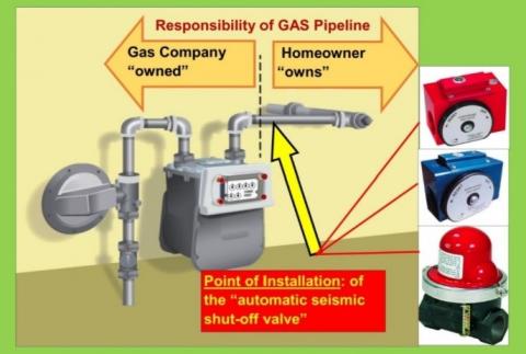
Earthquake natural gas shut-off valve (also known as a seismic natural gas shut-off valve) automatically shuts off your natural gas service when an earthquake of a sufficient magnitude occurs at your home.
An excess-flow valve (EFV) automatically closes and restricts the flow of natural gas in the event an underground pipe is damaged or if there is a significant increase in the flow of natural gas to the meter.
If you want to have an earthquake natural gas shut-off installed, or are required to have one by your insurance company or the local Department of Building and Safety, the valve must be installed on your house line.
If installation requires natural gas service closure, you"ll need to contact us to shut off the service and restore service when installation is completed. Natural gas service shut off and restoration of service orders can be scheduled by contacting us at 1-800-427-2200.
Under the regulations of the California Public Utilities Commission (CPUC), General Order 112-E, only SoCalGas® or its certified contractors are authorized to operate the natural gas service shut-off valve.
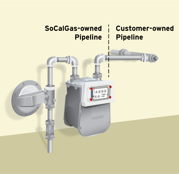
When you hire a qualified professional to install your earthquake valve, you"ll need to make sure that the valve is installed on your house line, not on SoCalGas" facilities. SoCalGas" facilities include all of the pipe fittings installed and maintained by SoCalGas, up to and including the last elbow or tee connecting to your house line. See the diagram below for to see where your house line starts.
All unauthorized valve installations found on SoCalGas" facilities will be removed. In addition, earthquake valves are not permitted in utility curb meter vaults.
If an earthquake or other significant event causes your earthquake shut-off or excess-flow valve to close, you can follow the manufacturer"s instructions for resetting the valve so that natural gas flows again. However, we recommend that you contact a qualified professional or SoCalGas to reset the valve, and to perform a safety check of your natural gas appliances before they are placed back in operation to verify that no natural gas leaks exist, and to re-light your pilot lights.
Remember that following a major emergency it may take many days or even weeks before someone can come to your location. (SoCalGas charges a fee to reset valves and re-light pilot lights when your earthquake shut-off valve has closed due to a non-earthquake occurrence.)
Price: The cost of the valve is going to vary based on the type and size of the valve, as well as the installation requirements and the company installing it.
Choosing a valve: In order to choose the right valve size and manufacturer, contact your local Department of Building and Safety to find out their earthquake valve requirements.
Where to buy a valve: You can purchase an earthquake valve at supply retailers, licensed plumbing contractors, or directly from the valve manufacturer.
Using a contractor: You can hire a qualified professional to install the earthquake or excess-flow valve on your house line. SoCalGas will not install a valve for you.
Effective February 10, 2002, California Public Utility Commission (CPUC) Decision 01-11-068 prohibits installation of an earthquake valve on SoCalGas" facilities. In addition, SoCalGas no longer installs earthquake shut-off valves for its customers, and does not allow any customer owned equipment, including excess-flow valves, be installed on SoCalGas" facilities.
If you have an earthquake valve that was installed by SoCalGas or one of its authorized contractors on or before the February 10, 2002 cutoff date, that is located on SoCalGas" facilities, with proper documentation your installation may be allowed to remain in place. Authorized contractors are those who participated in SoCalGas" earthquake program and were trained by SoCalGas to work on their facilities.
Additional information regarding earthquake valves and natural gas service restoration after a valve activates can be found in Tariff Book, Rule 10, Section G, "Earthquake Valve Service."
An Excess Flow Valve, or EFV, is a safety device installed on natural gas distribution pipelines to automatically close and restrict the flow of natural gas in the event an underground pipe is damaged or if there is a significant increase in the flow of natural gas to the meter. These conditions are typically caused by digging or construction but can also be caused by damage to your natural gas meter by a vehicle impact.
EFV can reduce the risk of explosions, fires, and personal injury because they close or restrict any unplanned or excessive natural gas flow. Installation of an EFV will not protect a customer from household appliance malfunctions, small punctures in underground pipelines, and pipeline damage from earthquakes or flooding. It is
important to understand that an EFV does not shut off the flow of natural gas completely. Some leakage may still occur resulting in a hazardous condition.
An EFV is installed on the service pipeline that runs underground between the natural gas main (usually located in or near the street, alley or easement) and the SoCalGas® meter on the customer’s property).
The best way to prevent damage to a natural gas pipeline due to digging is to call 811, the Underground Service Alert program, at least two working days before digging. Underground Service Alert will coordinate with SoCalGas to mark the locations of buried utility-owned lines - absolutely FREE.
If you are interested in having an EFV installed on the service pipeline serving you[1], please call SoCalGas at 1-800-427-2200. SoCalGas will first check to see if your service already has an EFV installed and, if not, an estimate to install the EFV will be provided. The cost to install an EFV can vary widely depending on site specific conditions and can range from $2,500 to $5,000 or more.
If you decide to have an EFV installed, we will coordinate with you to schedule the installation (note that it is possible that natural gas service will be interrupted to install the EFV). The construction crew will dig around the natural gas line in order to install the EFV and when the job is complete natural gas service will be restored (if it was shut off). If paving or concrete needs repair that work will be scheduled at a later date.

Seismic shut-off valves are a simple, but effective way to ensure you never experience a gas fire after an earthquake. They are designed for earthquakes, accidents and any event of impact. We have installed thousands of automatic gas shut off valves to the manufacture’s specification to ensure safe, trouble free use.
The seismic valves work on a simple, consistent and accurate principle. A sensor moves when the valve is subjected to a 5.4 magnitude or larger earthquake, releasing the valve float which blocks the line and prevents gas going in to the building. The valve is then manually reset once a safety inspection has been done and you’re sure there are no leaks in the building.
Each valve is tested and certified before leaving the factory to meet approval from the State Board of Architect and LA Counties stringent requirements. They are tested to ASCE 25-97, State of California 12-23-1 & ANSI Z21.70-1981 Standards for Seismic Gas Valves.
Some cities and counties in California have regulations that require the installation of automatic gas shut-off devices, which may include excess flow gas shut-off valves and/or seismic gas shut-off valves. Regulations vary, but generally apply to new building construction, or significant alterations or additions to existing buildings.
If a customer installs an automatic gas shut-off valve, it should be one that is certified by the State of California and it should be installed by a licensed plumbing contractor in accordance to the manufacturers instructions.PG&Edoes not install or service seismic actuated or excess flow gas shut-off valves, or recommend specific contractors for customer applications.
Non-emergency shut-offs will occur if the automatic gas shut-off is not installed according to manufacturer’s specifications. For example, the impact of heavy vehicles can trigger a non-emergency shut-off. They operate on movement and shut off the supply of gas to a building, when triggered by a 5.4 magnitude or larger Earthquake.

WITT is a manufacturer of Pressure relief valvesor Safety relief valves for technical gases. They are designed to protect against overpressure by discharging pressurized gases and vapors from pipelines, pressure vessels and plant components. Safety relief valves (SRV) are often the last line of defense against explosion – and such an explosion could be fatal. Other common names for safety relief valves are pressure relief valve (PRV), safety valve, pressure safety valve, overpressure valve, relief valve or blow-off valve.
WITT safety valves are very precise. They are individually preset to open at a predetermined pressure within the range 0.07 to 652 Psi. Their small size and orientation-independent installation allow a wide range of connection options. WITT relief valves also stand out due to their high blow-off flow rates of up to 970m³/h. They can be used within a temperature range of -76° F to +518°F and even with very low pressures.
For maximum safety, WITT undertakes 100 % testing of each safety relief valve before it is delivered. In addition, WITT offers individual testing of eachsafety valveby the TÜV, with their certificate as proof of the correct set pressure.
WITTsafety relief valvesare direct-acting, spring-loaded valves. When the preset opening pressure is reached, a spring-loaded element in the valve gives way and opens, and the pressure is relieved. Once the pressures are equalized, the valve closes automatically and can be reactivated any time the pressure rises again. Depending on the application and the nature of the gas, the safety relief valvescan either discharge to atmosphere, or via a connected blow-off line. The opening pressure of the safety valves is preset by WITT at the factory according to the customer’s requirements.
Safety relief valvesare used in numerous industries and industrial applications where, for example, gases pass through pipelines or where special process vessels have to be filled with gas at a certain pressure.
These include, among other things:Pipeline, plant and container constructionIndustrial furnace constructionInsulators and reactors (e.g. “glovebox” systems)hydrogen-powered vehiclesAdditive manufacturing (3D printer)
For most industrial applications using technical gases, brass is usually the standard material of construction of thesafety relief valvebody/housing. For the use of pressure relief valves with aggressive and corrosive gases, the housings are made of high-quality stainless steel (1.4541/AISI 321, 1.4404/AISI 316L, 1.4305/AISI 303 or 1.4571/AISI 316Ti). The use of aluminium as a housing material is also possible.
Depending on the type of gas used and individual customer requirements, various sealing materials and elastomers are available to ensure the safety of your systems under even the most difficult conditions.
WITT pressure relief valves are available with different connections. In addition to the standard versions with the usual internal or external threads, special versions with KF or CF flanges, VCR or UNF threads can also be ordered. Special adapters for connecting the safety relief valve to a blow-off line are also available.
NOTE: Once you have shut off the gas at the meter, do not try to turn it back on yourself. If the gas service shutoff valve is closed, PG&E or another qualified professional should perform a safety inspection before the gas service is restored and appliance pilots are relit.
PG&E crews will need to gain access to properties. Every gas meter must be inspected and gas crews must ensure that no gas is flowing on the customer"s property. Turning gas off at every meter is a necessary first step.
As reminder, PG&E employees always carry their identification and are always willing to show it to you. Customers should always ask to see valid identification before allowing anyone claiming to be a PG&E representative inside their home. If a person claiming to be a PG&E employee has identification and you still feel uncomfortable, call PG&E’s customer service line at 1-800-743-5000 to verify PG&E"s presence in the community.
It is important to know which appliances in your home run on gas. The most common gas appliances are stove top ranges, ovens, water heaters and furnaces.
Many older gas appliances and most water heaters have a small, continuously burning gas flame—the pilot light—that ignites the main burner. Some newer models have electronic igniters.
If the pilot light is out, shut the gas off at the appliance’s gas shutoff valve. Always wait five minutes to let gas disperse before trying to relight an appliance pilot light.
Follow the appliance manufacturer"s instructions to relight a pilot light. Often, basic relight instructions are located inside the main burner compartment door. If you cannot relight the pilot light yourself, call PG&E or another qualified professional for assistance.
Most gas appliances have a gas shutoff valve located near the appliance that lets you turn off the gas to that appliance only. In some cases, turning off the gas at the appliance"s shutoff valve will suffice if there is a gas leak or the appliance needs to be replaced or serviced. You should have an appliance gas shutoff valve installed at each gas appliance so that you can turn off the gas to that appliance only, instead of shutting off all gas at the main gas service shutoff valve.
When lighting the burners, light the match before you turn on the gas. If the flame goes out, turn off the burner and let the gas disperse before relighting.
Clean away any grease, oil or debris from the area to prevent a grease fire. In the event of a grease fire, never add water. Use baking soda or, if the fire is in a pan, use a lid to smother the flame. Stock your kitchen with a fire extinguisher.
If your water heater is elevated, make sure the platform is sturdy enough to withstand the weight of the water heater if it moves during an earthquake.
Do not use anything that could be a source of ignition, including cell phones, flashlights, light switches, matches or vehicles, until you are a safe distance away.

These valves do not fail very often. Normally the problem is with the ignitor not drawing enough amperage to open the valve. Even if the ignitor is glowing orange it is likely still the cause of the burner not igniting. Technicians refer to this as a "weak" igniter.
Dual gas safety valve assembly. The gas oven safety valve works with the oven igniter to provide gas to the burner. If the safety valve fails, the oven won’t heat. Since safety valves rarely fail, be sure to check more commonly defective parts before replacing the safety valve.
These valves do not fail very often. Normally the problem is with the ignitor not drawing enough amperage to open the valve. Even if the ignitor is glowing orange it is likely still the cause of the burner not igniting. Technicians refer to this as a "weak" igniter.
These valves do not fail very often. Normally the problem is with the ignitor not drawing enough amperage to open the valve. Even if the ignitor is glowing orange it is likely still the cause of the burner not igniting. Technicians refer to this as a "weak" igniter.
These valves do not fail very often. Normally the problem is with the ignitor not drawing enough amperage to open the valve. Even if the ignitor is glowing orange it is likely still the cause of the burner not igniting. Technicians refer to this as a "weak" igniter.
These valves do not fail very often. Normally the problem is with the ignitor not drawing enough amperage to open the valve. Even if the ignitor is glowing orange it is likely still the cause of the burner not igniting. Technicians refer to this as a "weak" igniter.
These valves do not fail very often. Normally the problem is with the ignitor not drawing enough amperage to open the valve. Even if the ignitor is glowing orange it is likely still the cause of the burner not igniting. Technicians refer to this as a "weak" igniter.
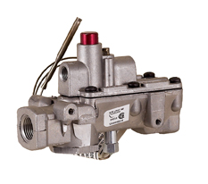
Gas Safety ValvesThese valves automatically control main gas flow. Our automatic pilot valves shut off both the main and pilot gases. Pilot gas is tapped from the main line within the control. Gas will flow only to the pilot burner when the reset button is depressed. The manual pilot valve stop can be adjusted for maximum pilot flow.
Pilot BurnersThese “J Series” combination pilot burners are universal replacement pilot burners and are supplied in three models. Mounting brackets on all four sides of each burner permit adaptation to almost any application. We also offer pilot burner fittings (R Series) and replacement flame sensors and inlet fittings (Y Series).


 8613371530291