
how does a pressure safety valve work in stock

Curtiss-Wright"s selection of Pressure Relief Valves comes from its outstanding product brands Farris and Target Rock. We endeavor to support the whole life cycle of a facility and continuously provide custom products and technologies. Boasting a reputation for producing high quality, durable products, our collection of Pressure Relief Valves is guaranteed to provide effective and reliable pressure relief.
While some basic components and activations in relieving pressure may differ between the specific types of relief valves, each aims to be 100% effective in keeping your equipment running safely. Our current range includes numerous valve types, from flanged to spring-loaded, threaded to wireless, pilot operated, and much more.
A pressure relief valve is a type of safety valve designed to control the pressure in a vessel. It protects the system and keeps the people operating the device safely in an overpressure event or equipment failure.
A pressure relief valve is designed to withstand a maximum allowable working pressure (MAWP). Once an overpressure event occurs in the system, the pressure relief valve detects pressure beyond its design"s specified capability. The pressure relief valve would then discharge the pressurized fluid or gas to flow from an auxiliary passage out of the system.
Below is an example of one of our pilot operated pressure relief valves in action; the cutaway demonstrates when high pressure is released from the system.
Air pressure relief valves can be applied to a variety of environments and equipment. Pressure relief valves are a safety valve used to keep equipment and the operators safe too. They"re instrumental in applications where proper pressure levels are vital for correct and safe operation. Such as oil and gas, power generation like central heating systems, and multi-phase applications in refining and chemical processing.
At Curtiss-Wright, we provide a range of different pressure relief valves based on two primary operations – spring-loaded and pilot operated. Spring-loaded valves can either be conventional spring-loaded or balanced spring-loaded.
Spring-loaded valves are programmed to open and close via a spring mechanism. They open when the pressure reaches an unacceptable level to release the material inside the vessel. It closes automatically when the pressure is released, and it returns to an average operating level. Spring-loaded safety valves rely on the closing force applied by a spring onto the main seating area. They can also be controlled in numerous ways, such as a remote, control panel, and computer program.
Pilot-operated relief valves operate by combining the primary relieving device (main valve) with self-actuated auxiliary pressure relief valves, also known as the pilot control. This pilot control dictates the opening and closing of the main valve and responds to system pressure. System pressure is fed from the inlet into and through the pilot control and ultimately into the main valve"s dome. In normal operating conditions, system pressure will prevent the main valve from opening.
The valves allow media to flow from an auxiliary passage and out of the system once absolute pressure is reached, whether it is a maximum or minimum level.
When the pressure is below the maximum amount, the pressure differential is slightly positive on the piston"s dome size, which keeps the main valve in the closed position. When system pressure rises and reaches the set point, the pilot will cut off flow to the dome, causing depressurization in the piston"s dome side. The pressure differential has reversed, and the piston will rise, opening the main valve, relieving pressure.
When the process pressure decreases to a specific pressure, the pilot closes, the dome is repressurized, and the main valve closes. The main difference between spring-loaded PRVs and pilot-operated is that a pilot-operated safety valve uses pressure to keep the valve closed.
Pilot-operated relief valves are controlled by hand and are typically opened often through a wheel or similar component. The user opens the valve when the gauge signifies that the system pressure is at an unsafe level; once the valve has opened and the pressure has been released, the operator can shut it by hand again.
Increasing pressure helps to maintain the pilot"s seal. Once the setpoint has been reached, the valve opens. This reduces leakage and fugitive emissions.
At set pressure the valve snaps to full lift. This can be quite violent on large pipes with significant pressure. The pressure has to drop below the set pressure in order for the piston to reseat.
The pilot is designed to open gradually, so that less of the system fluid is lost during each relief event. The piston lifts in proportion to the overpressure.
At Curtiss-Wright we also provide solutions for pressure relief valve monitoring. Historically, pressure relief valves have been difficult or impossible to monitor. Our SmartPRV features a 2600 Series pressure relief valve accessorized with a wireless position monitor that alerts plant operators during an overpressure event, including the time and duration.
There are many causes of overpressure, but the most common ones are typically blocked discharge in the system, gas blowby, and fire. Even proper inspection and maintenance will not eliminate the occurrence of leakages. An air pressure relief valve is the only way to ensure a safe environment for the device, its surroundings, and operators.
A PRV and PSV are interchangeable, but there is a difference between the two valves. A pressure release valve gradually opens when experiencing pressure, whereas a pressure safety valve opens suddenly when the pressure hits a certain level of over pressurization. Safety valves can be used manually and are typically used for a permanent shutdown. Air pressure relief valves are used for operational requirements, and they gently release the pressure before it hits the maximum high-pressure point and circulates it back into the system.
Pressure relief valves should be subject to an annual test, one per year. The operator is responsible for carrying out the test, which should be done using an air compressor. It’s imperative to ensure pressure relief valves maintain their effectiveness over time and are checked for signs of corrosion and loss of functionality. Air pressure relief valves should also be checked before their installation, after each fire event, and regularly as decided by the operators.
Direct-acting solenoid valves have a direct connection with the opening and closing armature, whereas pilot-operated valves use of the process fluid to assist in piloting the operation of the valve.
A control valve works by varying the rate of fluid passing through the valve itself. As the valve stem moves, it alters the size of the passage and increases, decreases or holds steady the flow. The opening and closing of the valve is altered whenever the controlled process parameter does not reach the set point.
Control valves are usually at floor level or easily accessible via platforms. They are also located on the same equipment or pipeline as the measurement and downstream or flow measurements.
An industrial relief valve is designed to control or limit surges of pressure in a system, most often in fluid or compressed air system valves. It does so as a form of protection for the system and defending against instrument or equipment failure. They are usually present in clean water industries.
A PRV is often referred to as a pressure relief valve, which is also known as a PSV or pressure safety valve. They are used interchangeably throughout the industry depending on company standards.

As soon as mankind was able to boil water to create steam, the necessity of the safety device became evident. As long as 2000 years ago, the Chinese were using cauldrons with hinged lids to allow (relatively) safer production of steam. At the beginning of the 14th century, chemists used conical plugs and later, compressed springs to act as safety devices on pressurised vessels.
Early in the 19th century, boiler explosions on ships and locomotives frequently resulted from faulty safety devices, which led to the development of the first safety relief valves.
In 1848, Charles Retchie invented the accumulation chamber, which increases the compression surface within the safety valve allowing it to open rapidly within a narrow overpressure margin.
Today, most steam users are compelled by local health and safety regulations to ensure that their plant and processes incorporate safety devices and precautions, which ensure that dangerous conditions are prevented.
The principle type of device used to prevent overpressure in plant is the safety or safety relief valve. The safety valve operates by releasing a volume of fluid from within the plant when a predetermined maximum pressure is reached, thereby reducing the excess pressure in a safe manner. As the safety valve may be the only remaining device to prevent catastrophic failure under overpressure conditions, it is important that any such device is capable of operating at all times and under all possible conditions.
Safety valves should be installed wherever the maximum allowable working pressure (MAWP) of a system or pressure-containing vessel is likely to be exceeded. In steam systems, safety valves are typically used for boiler overpressure protection and other applications such as downstream of pressure reducing controls. Although their primary role is for safety, safety valves are also used in process operations to prevent product damage due to excess pressure. Pressure excess can be generated in a number of different situations, including:
The terms ‘safety valve’ and ‘safety relief valve’ are generic terms to describe many varieties of pressure relief devices that are designed to prevent excessive internal fluid pressure build-up. A wide range of different valves is available for many different applications and performance criteria.
In most national standards, specific definitions are given for the terms associated with safety and safety relief valves. There are several notable differences between the terminology used in the USA and Europe. One of the most important differences is that a valve referred to as a ‘safety valve’ in Europe is referred to as a ‘safety relief valve’ or ‘pressure relief valve’ in the USA. In addition, the term ‘safety valve’ in the USA generally refers specifically to the full-lift type of safety valve used in Europe.
Pressure relief valve- A spring-loaded pressure relief valve which is designed to open to relieve excess pressure and to reclose and prevent the further flow of fluid after normal conditions have been restored. It is characterised by a rapid-opening ‘pop’ action or by opening in a manner generally proportional to the increase in pressure over the opening pressure. It may be used for either compressible or incompressible fluids, depending on design, adjustment, or application.
Safety valves are primarily used with compressible gases and in particular for steam and air services. However, they can also be used for process type applications where they may be needed to protect the plant or to prevent spoilage of the product being processed.
Relief valve - A pressure relief device actuated by inlet static pressure having a gradual lift generally proportional to the increase in pressure over opening pressure.
Relief valves are commonly used in liquid systems, especially for lower capacities and thermal expansion duty. They can also be used on pumped systems as pressure overspill devices.
Safety relief valve - A pressure relief valve characterised by rapid opening or pop action, or by opening in proportion to the increase in pressure over the opening pressure, depending on the application, and which may be used either for liquid or compressible fluid.
In general, the safety relief valve will perform as a safety valve when used in a compressible gas system, but it will open in proportion to the overpressure when used in liquid systems, as would a relief valve.
Safety valve- A valve which automatically, without the assistance of any energy other than that of the fluid concerned, discharges a quantity of the fluid so as to prevent a predetermined safe pressure being exceeded, and which is designed to re-close and prevent further flow of fluid after normal pressure conditions of service have been restored.

There is a wide range of safety valves available to meet the many different applications and performance criteria demanded by different industries. Furthermore, national standards define many varying types of safety valve.
The ASME standard I and ASME standard VIII for boiler and pressure vessel applications and the ASME/ANSI PTC 25.3 standard for safety valves and relief valves provide the following definition. These standards set performance characteristics as well as defining the different types of safety valves that are used:
ASME I valve - A safety relief valve conforming to the requirements of Section I of the ASME pressure vessel code for boiler applications which will open within 3% overpressure and close within 4%. It will usually feature two blowdown rings, and is identified by a National Board ‘V’ stamp.
ASME VIII valve- A safety relief valve conforming to the requirements of Section VIII of the ASME pressure vessel code for pressure vessel applications which will open within 10% overpressure and close within 7%. Identified by a National Board ‘UV’ stamp.
Full bore safety valve - A safety valve having no protrusions in the bore, and wherein the valve lifts to an extent sufficient for the minimum area at any section, at or below the seat, to become the controlling orifice.
Conventional safety relief valve -The spring housing is vented to the discharge side, hence operational characteristics are directly affected by changes in the backpressure to the valve.
Balanced safety relief valve -A balanced valve incorporates a means of minimising the effect of backpressure on the operational characteristics of the valve.
Pilot operated pressure relief valve -The major relieving device is combined with, and is controlled by, a self-actuated auxiliary pressure relief device.
Power-actuated safety relief valve - A pressure relief valve in which the major pressure relieving device is combined with, and controlled by, a device requiring an external source of energy.
Standard safety valve - A valve which, following opening, reaches the degree of lift necessary for the mass flowrate to be discharged within a pressure rise of not more than 10%. (The valve is characterised by a pop type action and is sometimes known as high lift).
Full lift (Vollhub) safety valve -A safety valve which, after commencement of lift, opens rapidly within a 5% pressure rise up to the full lift as limited by the design. The amount of lift up to the rapid opening (proportional range) shall not be more than 20%.
Direct loaded safety valve -A safety valve in which the opening force underneath the valve disc is opposed by a closing force such as a spring or a weight.
Proportional safety valve - A safety valve which opens more or less steadily in relation to the increase in pressure. Sudden opening within a 10% lift range will not occur without pressure increase. Following opening within a pressure of not more than 10%, these safety valves achieve the lift necessary for the mass flow to be discharged.
Diaphragm safety valve -A direct loaded safety valve wherein linear moving and rotating elements and springs are protected against the effects of the fluid by a diaphragm
Bellows safety valve - A direct loaded safety valve wherein sliding and (partially or fully) rotating elements and springs are protected against the effects of the fluids by a bellows. The bellows may be of such a design that it compensates for influences of backpressure.
Controlled safety valve - Consists of a main valve and a control device. It also includes direct acting safety valves with supplementary loading in which, until the set pressure is reached, an additional force increases the closing force.
Safety valve - A safety valve which automatically, without the assistance of any energy other than that of the fluid concerned, discharges a quantity of the fluid so as to prevent a predetermined safe pressure being exceeded, and which is designed to re-close and prevent further flow of fluid after normal pressure conditions of service have been restored. Note; the valve can be characterised either by pop action (rapid opening) or by opening in proportion (not necessarily linear) to the increase in pressure over the set pressure.
Direct loaded safety valve -A safety valve in which the loading due to the fluid pressure underneath the valve disc is opposed only by a direct mechanical loading device such as a weight, lever and weight, or a spring.
Assisted safety valve -A safety valve which by means of a powered assistance mechanism, may additionally be lifted at a pressure lower than the set pressure and will, even in the event of a failure of the assistance mechanism, comply with all the requirements for safety valves given in the standard.
Supplementary loaded safety valve - A safety valve that has, until the pressure at the inlet to the safety valve reaches the set pressure, an additional force, which increases the sealing force.
Note; this additional force (supplementary load), which may be provided by means of an extraneous power source, is reliably released when the pressure at the inlet of the safety valve reaches the set pressure. The amount of supplementary loading is so arranged that if such supplementary loading is not released, the safety valve will attain its certified discharge capacity at a pressure not greater than 1.1 times the maximum allowable pressure of the equipment to be protected.
Pilot operated safety valve -A safety valve, the operation of which is initiated and controlled by the fluid discharged from a pilot valve, which is itself, a direct loaded safety valve subject to the requirement of the standard.
The common characteristic shared between the definitions of conventional safety valves in the different standards, is that their operational characteristics are affected by any backpressure in the discharge system. It is important to note that the total backpressure is generated from two components; superimposed backpressure and the built-up backpressure:
Subsequently, in a conventional safety valve, only the superimposed backpressure will affect the opening characteristic and set value, but the combined backpressure will alter the blowdown characteristic and re-seat value.
The ASME/ANSI standard makes the further classification that conventional valves have a spring housing that is vented to the discharge side of the valve. If the spring housing is vented to the atmosphere, any superimposed backpressure will still affect the operational characteristics. Thiscan be seen from Figure 9.2.1, which shows schematic diagrams of valves whose spring housings are vented to the discharge side of the valve and to the atmosphere.
By considering the forces acting on the disc (with area AD), it can be seen that the required opening force (equivalent to the product of inlet pressure (PV) and the nozzle area (AN)) is the sum of the spring force (FS) and the force due to the backpressure (PB) acting on the top and bottom of the disc. In the case of a spring housing vented to the discharge side of the valve (an ASME conventional safety relief valve, see Figure 9.2.1 (a)), the required opening force is:
In both cases, if a significant superimposed backpressure exists, its effects on the set pressure need to be considered when designing a safety valve system.
Once the valve starts to open, the effects of built-up backpressure also have to be taken into account. For a conventional safety valve with the spring housing vented to the discharge side of the valve, see Figure 9.2.1 (a), the effect of built-up backpressure can be determined by considering Equation 9.2.1 and by noting that once the valve starts to open, the inlet pressure is the sum of the set pressure, PS, and the overpressure, PO.
Balanced safety valves are those that incorporate a means of eliminating the effects of backpressure. There are two basic designs that can be used to achieve this:
Although there are several variations of the piston valve, they generally consist of a piston type disc whose movement is constrained by a vented guide. The area of the top face of the piston, AP, and the nozzle seat area, AN, are designed to be equal. This means that the effective area of both the top and bottom surfaces of the disc exposed to the backpressure are equal, and therefore any additional forces are balanced. In addition, the spring bonnet is vented such that the top face of the piston is subjected to atmospheric pressure, as shown in Figure 9.2.2.
The bellows arrangement prevents backpressure acting on the upper side of the disc within the area of the bellows. The disc area extending beyond the bellows and the opposing disc area are equal, and so the forces acting on the disc are balanced, and the backpressure has little effect on the valve opening pressure.
Bellows failure is an important concern when using a bellows balanced safety valve, as this may affect the set pressure and capacity of the valve. It is important, therefore, that there is some mechanism for detecting any uncharacteristic fluid flow through the bellows vents. In addition, some bellows balanced safety valves include an auxiliary piston that is used to overcome the effects of backpressure in the case of bellows failure. This type of safety valve is usually only used on critical applications in the oil and petrochemical industries.
In addition to reducing the effects of backpressure, the bellows also serve to isolate the spindle guide and the spring from the process fluid, this is important when the fluid is corrosive.
Since balanced pressure relief valves are typically more expensive than their unbalanced counterparts, they are commonly only used where high pressure manifolds are unavoidable, or in critical applications where a very precise set pressure or blowdown is required.
This type of safety valve uses the flowing medium itself, through a pilot valve, to apply the closing force on the safety valve disc. The pilot valve is itself a small safety valve.
The diaphragm type is typically only available for low pressure applications and it produces a proportional type action, characteristic of relief valves used in liquid systems. They are therefore of little use in steam systems, consequently, they will not be considered in this text.
The piston type valve consists of a main valve, which uses a piston shaped closing device (or obturator), and an external pilot valve. Figure 9.2.4 shows a diagram of a typical piston type, pilot operated safety valve.
The piston and seating arrangement incorporated in the main valve is designed so that the bottom area of the piston, exposed to the inlet fluid, is less than the area of the top of the piston. As both ends of the piston are exposed to the fluid at the same pressure, this means that under normal system operating conditions, the closing force, resulting from the larger top area, is greater than the inlet force. The resultant downward force therefore holds the piston firmly on its seat.
If the inlet pressure were to rise, the net closing force on the piston also increases, ensuring that a tight shut-off is continually maintained. However, when the inlet pressure reaches the set pressure, the pilot valve will pop open to release the fluid pressure above the piston. With much less fluid pressure acting on the upper surface of the piston, the inlet pressure generates a net upwards force and the piston will leave its seat. This causes the main valve to pop open, allowing the process fluid to be discharged.
When the inlet pressure has been sufficiently reduced, the pilot valve will reclose, preventing the further release of fluid from the top of the piston, thereby re-establishing the net downward force, and causing the piston to reseat.
Pilot operated safety valves offer good overpressure and blowdown performance (a blowdown of 2% is attainable). For this reason, they are used where a narrow margin is required between the set pressure and the system operating pressure. Pilot operated valves are also available in much larger sizes, making them the preferred type of safety valve for larger capacities.
One of the main concerns with pilot operated safety valves is that the small bore, pilot connecting pipes are susceptible to blockage by foreign matter, or due to the collection of condensate in these pipes. This can lead to the failure of the valve, either in the open or closed position, depending on where the blockage occurs.
The terms full lift, high lift and low lift refer to the amount of travel the disc undergoes as it moves from its closed position to the position required to produce the certified discharge capacity, and how this affects the discharge capacity of the valve.
A full lift safety valve is one in which the disc lifts sufficiently, so that the curtain area no longer influences the discharge area. The discharge area, and therefore the capacity of the valve are subsequently determined by the bore area. This occurs when the disc lifts a distance of at least a quarter of the bore diameter. A full lift conventional safety valve is often the best choice for general steam applications.
The disc of a high lift safety valve lifts a distance of at least 1/12th of the bore diameter. This means that the curtain area, and ultimately the position of the disc, determines the discharge area. The discharge capacities of high lift valves tend to be significantly lower than those of full lift valves, and for a given discharge capacity, it is usually possible to select a full lift valve that has a nominal size several times smaller than a corresponding high lift valve, which usually incurs cost advantages.Furthermore, high lift valves tend to be used on compressible fluids where their action is more proportional.
In low lift valves, the disc only lifts a distance of 1/24th of the bore diameter. The discharge area is determined entirely by the position of the disc, and since the disc only lifts a small amount, the capacities tend to be much lower than those of full or high lift valves.
Except when safety valves are discharging, the only parts that are wetted by the process fluid are the inlet tract (nozzle) and the disc. Since safety valves operate infrequently under normal conditions, all other components can be manufactured from standard materials for most applications. There are however several exceptions, in which case, special materials have to be used, these include:
Cast steel -Commonly used on higher pressure valves (up to 40 bar g). Process type valves are usually made from a cast steel body with an austenitic full nozzle type construction.
For all safety valves, it is important that moving parts, particularly the spindle and guides are made from materials that will not easily degrade or corrode. As seats and discs are constantly in contact with the process fluid, they must be able to resist the effects of erosion and corrosion.
For process applications, austenitic stainless steel is commonly used for seats and discs; sometimes they are ‘stellite faced’ for increased durability. For extremely corrosive fluids, nozzles, discs and seats are made from special alloys such as ‘monel’ or ‘hastelloy’.
The spring is a critical element of the safety valve and must provide reliable performance within the required parameters. Standard safety valves will typically use carbon steel for moderate temperatures. Tungsten steel is used for higher temperature, non-corrosive applications, and stainless steel is used for corrosive or clean steam duty. For sour gas and high temperature applications, often special materials such as monel, hastelloy and ‘inconel’ are used.
A key option is the type of seating material used. Metal-to-metal seats, commonly made from stainless steel, are normally used for high temperature applications such as steam. Alternatively, resilient discs can be fixed to either or both of the seating surfaces where tighter shut-off is required, typically for gas or liquid applications. These inserts can be made from a number of different materials, but Viton, nitrile or EPDM are the most common. Soft seal inserts are not generally recommended for steam use.
Standard safety valves are generally fitted with an easing lever, which enables the valve to be lifted manually in order to ensure that it is operational at pressures in excess of 75% of set pressure. This is usually done as part of routine safety checks, or during maintenance to prevent seizing. The fitting of a lever is usually a requirement of national standards and insurance companies for steam and hot water applications. For example, the ASME Boiler and Pressure Vessel Code states that pressure relief valves must be fitted with a lever if they are to be used on air, water over 60°C, and steam.
A standard or open lever is the simplest type of lever available. It is typically used on applications where a small amount of leakage of the fluid to the atmosphere is acceptable, such as on steam and air systems, (see Figure 9.2.5 (a)).
Where it is not acceptable for the media to escape, a packed lever must be used. This uses a packed gland seal to ensure that the fluid is contained within the cap, (see Figure 9.2.5 (b)).
For service where a lever is not required, a cap can be used to simply protect the adjustment screw. If used in conjunction with a gasket, it can be used to prevent emissions to the atmosphere, (see Figure 9.2.6).
A test gag (Figure 9.2.7) may be used to prevent the valve from opening at the set pressure during hydraulic testing when commissioning a system. Once tested, the gag screw is removed and replaced with a short blanking plug before the valve is placed in service.
The amount of fluid depends on the particular design of safety valve. If emission of this fluid into the atmosphere is acceptable, the spring housing may be vented to the atmosphere – an open bonnet. This is usually advantageous when the safety valve is used on high temperature fluids or for boiler applications as, otherwise, high temperatures can relax the spring, altering the set pressure of the valve. However, using an open bonnet exposes the valve spring and internals to environmental conditions, which can lead to damage and corrosion of the spring.
When the fluid must be completely contained by the safety valve (and the discharge system), it is necessary to use a closed bonnet, which is not vented to the atmosphere. This type of spring enclosure is almost universally used for small screwed valves and, it is becoming increasingly common on many valve ranges since, particularly on steam, discharge of the fluid could be hazardous to personnel.
Some safety valves, most commonly those used for water applications, incorporate a flexible diaphragm or bellows to isolate the safety valve spring and upper chamber from the process fluid, (see Figure 9.2.9).
An elastomer bellows or diaphragm is commonly used in hot water or heating applications, whereas a stainless steel one would be used on process applications employing hazardous fluids.

Discovering the safety device used in most industry for pressure flow control, pressure relief valve it’s called. It’s an equipment that must be found in the industry to control an over-pressurized vessel.
So, a pressure relief valve is a safety device designed to secure a pressurized system during an overpressure occurrence during operation. The system is widely available today as an electronic, pneumatic and hydraulic system. The various types serve the same purpose in different applications and are called pressure relief valve, relief valve or safety valve.
Depending on the type of system, the power source could be electricity or compressed air for operation. Since its purpose is to control the pressure so that life and properties can be safe. A pressure relief valve must be capable to serve for a long period of time and capable of operating at all times. And a professional operator with experience must be in charge to ensure proper working as there is no room for error.
Today we’ll be looking at the definition, functions, applications, working, types, components, considerations, benefits and limitations of a pressure relief valve.
A pressure relief valve or relief valve is a special type of safety valve system used to control or limit the pressure in a system. It can be manually or automatically controlled from a pressurized vessel or piping system. The pressurized fluid or gas is discharged to a reservoir or atmosphere to relieve pressure in excess of the maximum allowable working pressure (MAWP).
The primary purpose of a pressure relief valve is to protect pressure vessels or system from catastrophic failure. Catastrophic failure could be disastrous during an overpressure event, could either be liquid or gaseous.
This device is widely used in petrochemical, petroleum refining, chemical manufacturing industries. Industries where natural gas processing occurs and power generation, as well as water supply industries, also make good use of pressure relief valve. Though it’s generally known as relief valve depending on its field of application it can be called pressure relief valve (PRV), pressure safety valve (PSV), or safety valve. You should note the design and operation of these valves are slightly different.
The working of a relief valve is quite complex but can be easily understood. It consists of ball, poppet or spool opposed by a spring which is placed into a cavity or ported body. A hydraulic system is often used to limit fluid pressure in the part of the circuit they are installed.
The poppet is in the form of a disc or cone shape object that is mounted within an opposite machine seat. If the part is forced closed by spring pressure, very low leakage will be providing. The spool is a cylindrical, machined steel rod with metering grooves or notches that’s also stopped by spring pressure. It leaks more than a poppet valve but offers superior metering effects.
and rapid response when the device opens to bleed excess fluid into a reservoir. The fluid could be liquid, gas or liquid-gas. This reduces the pressure equal to its spring setting. the device open as the pressure caused by backpressure or downstream is high enough to force the poppet or spool to open against its spring.
In the working of a relief valve, excessive pressurized fluid is provided from an open path to a tank with the purpose of reducing work port pressure. As soon as the fluid pressure begins to rise, the force is applied to the bottom of the spool or poppet. This allows the valve to open modestly at first, bleeding little fluid as required to maintain the downstream pressure. But if the downstream pressure continues to rise, the force acting upon the poppet or spool will be pushing it further towards the spring until the point spring force is balanced by the hydraulic force.
The pressure rise is as a result of load pressure combination, backpressure, and energy required to flow through the valve itself. The initial fluid force overcomes the seated force of the spring by the help of the cracking pressure. As the valve flows more fluid to the tank, the rate of pressure rise is safe because the forces of the pressurized fluid counteract the compression rate of the spring. If the valve is nearly fully open, pressure rise increases again as the valve bottom opens due to the flow forces.
As the operation or backpressure decreases, the valve begins to close. This is done at differing rates than the opening. The difference between the opening and closing curve is called its hysteresis, it’s indicative and instruction of the quality of its construction. This is because higher quality valves with advanced construction allow lower pressure rise with better hysteresis.
the conventional spring-loaded types of relief valve that contained the bonnet, spring, and guide in the released fluids. Its relief pressure backpressure decreases the set pressure if the bonnet is vented to the atmosphere. But, if the bonnet is vented internally to the outlet, the relief-system backpressure increases the set pressure.
The design of a balanced spring-loaded is to protect the bonnet spring, and guide from the released fluids and reduce the effects of backpressure. Its disk area is vented to the atmosphere and another disk is exposed to backpressure. The vented disk is equal to the exposed disk.
The pilot-operated valve is controlled by an auxiliary pressure pilot. The resistance force on the piston in the main valve is achieved by the pressure during the operation through an orifice. The net seating force on the piston actually rises as the process pressure nears the set point.
a safety valve is a pressure relief valve that works by inlet static pressure and design to rapidly open with a pop action. It is widely used for air and stream services. A safety valve is available in two forms:
Full-lift safety valve: in this safety valve the disc is also automatically lifted but the actual charge area is not determined by the position of the disc.
A relief valve is a pressure relief device design with an inlet static pressure for its working. It has a gradual lift generally proportional to the increase in pressure over opening pressure. It’s suitable for close discharge system as it is enclosed in a spring housing.
A safety relief valve is a pressure relief valve characterized by its rapid opening or pop action. Also known for its opening in proportion to the increase in pressure over the opening pressure base on its application. Safety relief valves are used either for liquid or compressible fluid. The common type is the conventional and balanced safety relief valve which were earlier explained.
A power actuated pressure relief valve contained a relieving device that is joined with and controlled by a device requiring an external source of energy.
A vacuum relief valve is a pressure relief device that admits fluid to prevent an excessive internal vacuum. It’s designed to reclose so as to prevent further flow of fluid after normal conditions have been restored.
Selecting appropriate relief devices to handle the imposed loads. Several components must be put into consideration. Parts like set pressure, backpressure, dual relief valve, multiple relief valves must suit the capacity of the relieving device.
In conclusion, a pressure relief valve is a safety device used in the industrial world to save lives and properties. We saw the various types and components of pressure relief valve, how it works and also selection consideration.

RM2BHFJN7–Coryton, Stanford-le-Hope, Essex, UK. 25th Apr, 2020. A build up of pressure caused a safety valve to release at a power station (initially thought to be the oil refinery nearby) in Coryton, close to DP World port cranes on the Thames Estuary, creating steam and noise in the area leading people to believe that there had been an explosion. Local fire brigade and emergency services attended
RMT94YD7–Papin holding a diagram of a steam engine, lithograph, 1689. Denis Papin (August 22, 1647 - 1712) was a French physicist, mathematician and inventor. He worked with Robert Boyle from 1676-79, publishing an account of his work in Continuation of New Experiments (1680). During this period, Papin invented the steam digester, a type of pressure cooker with a safety valve.
RMGE4JB3–(September 6, 1963) Vent flowing cryogenic fuel and T/C Rake mounted on a 1/10 scale model Centaur in the l0 x l0 Foot Supersonic Wind Tunnel. The fuel being used is liquid hydrogen. The point of the test is to determine how far to expel venting fuel from the rocket body to prevent explosion at the base of the vehicle. This vent is used as a safety valve for the fumes created when loading the fuel tanks during launch preparation. Liquid hydrogen has to be kept at a very low temperature. As it heats, it turns to gas and increases pressure in the tank. It therefore has to be vented overboard whi
RMMR3WYE–Illustration depicting Papin"s steam engine (1707) for pumping water from mines. It was the first engine to use the safety valve he had invented twenty-seven years earlier for his "digester". (1647-1713) a French physicist, mathematician and inventor, best known for his pioneering invention of the steam digester, the forerunner of the pressure cooker and of the steam engine. Dated 19th century
RM2BHFJR5–Coryton, Stanford-le-Hope, Essex, UK. 25th Apr, 2020. A build up of pressure caused a safety valve to release at a power station (initially thought to be the oil refinery nearby) in Coryton, close to DP World port cranes on the Thames Estuary, creating steam and noise in the area leading people to believe that there had been an explosion. Local fire brigade and emergency services attended
RME14RJF–Apr. 18, 2012 - The main road through the area is always busy: The gaunt, Barren Hills are a constant reminder of the wilderness of the territory afar. The safety valve with its ever-burning flame at the top is behind the wire pending on the night.
RMCYXCAB–A well engineered brass and ferrous metal model gas fired horizontal stationary steam set, The brass boiler with metal cladding and normal fittings, weight and lever safety valve, main stop and lagged steam line to single horizontal cylinder¦ mill engine with overmounted valve chest and brass bound cylinder, barrelled connecting rod, counterbalanced crankshaft, spoked flywheel and multi rope pulley. Other details include feed water heater and hand feed pump ,the whole finished in maroon, black and polished brightwork and mounted on a brick and tiled plinth with, Additional-Rights-Clearences-NA
RMT965J2–Color enhanced lithograph of Papin holding a diagram of a steam engine, 1689. Denis Papin (August 22, 1647 - 1712) was a French physicist, mathematician and inventor. He worked with Robert Boyle from 1676-79, publishing an account of his work in Continuation of New Experiments (1680). During this period, Papin invented the steam digester, a type of pressure cooker with a safety valve.
RMW56XWK–Model of a Hydraulic Press, Model of a simple hydraulic press on a wooden floorboard. On the one hand is a manually operated pump, equipped with a pump arm, regulator, overflow and safety valve. The pump arm can be set in two positions. The regulator is a screw valve. The safety valve is adjusted with a weight. A tube for the liquid runs from the pump to the bottom of the press, where an oval press platform is pushed upwards., Joseph Bramah (possibly), United Kingdom, 1820, iron (metal), copper (metal), wood (plant material), model: h 41 cm × w 56 cm × d 27 cm packaging capsule: h 45.5 cm × w
RMMR3X05–Illustration depicting Papin"s steam engine (1707) for pumping water from mines. It was the first engine to use the safety valve he had invented twenty-seven years earlier for his "digester". (1647-1713) a French physicist, mathematician and inventor, best known for his pioneering invention of the steam digester, the forerunner of the pressure cooker and of the steam engine. Dated 19th century
RM2JM8GB6–Alain Sauthier, Director of Nant de Drance poses in front of a safety valve of the penstock in the newly operational Nant de Drance pumped storage electricity power plant in Finhaut, Switzerland, August 4, 2022. REUTERS/Denis Balibouse
RMCYXC6B–A well engineered brass and ferrous metal model gas fired horizontal stationary steam set, The brass boiler with metal cladding and normal fittings, weight and lever safety valve, main stop and lagged steam line to single horizontal cylinder¦ mill engine with overmounted valve chest and brass bound cylinder, barrelled connecting rod, counterbalanced crankshaft, spoked flywheel and multi rope pulley. Other details include feed water heater and hand feed pump ,the whole finished in maroon, black and polished brightwork and mounted on a brick and tiled plinth with, Additional-Rights-Clearences-NA
RF2JHG6MN–An industrial pressure safety valve, abbreviated as "psv" a well-known concept in the industry. Specially made to prevent dangerous high pressures in
RMP3880C–. Grand Geyser Cone and safety valve, Yellowstone National Park. Coverage: 1881-1889. Source Imprint: Fargo, D.T. : F. Jay Haynes, 1881-1889.. Digital item published 1-25-2006; updated 2-12-2009. 129 Grand Geyser Cone and safety valve, Yellowstone National Park, by Haynes, F. Jay (Frank Jay), 1853-1921
RM2JM8G81–Alain Sauthier, Director of Nant de Drance talks to a journalist in front of a safety valve of the penstock in the newly operational Nant de Drance pumped storage electricity power plant in Finhaut, Switzerland, August 4, 2022. REUTERS/Denis Balibouse
RF2JHG6N4–An industrial pressure safety valve, abbreviated as "psv" a well-known concept in the industry. Specially made to prevent dangerous high pressures in
RMP38806–. Grand Geyser Cone and safety valve, Yellowstone National Park. Coverage: 1881-1889. Source Imprint: Fargo, D.T. : F. Jay Haynes, 1881-1889.. Digital item published 1-25-2006; updated 2-12-2009. 129 Grand Geyser Cone and safety valve, Yellowstone National Park, by Haynes, F. Jay (Frank Jay), 1853-1921 2
RM2D3PPTK–Iraqi looters wave to the passing convoy of U.S. Marines as they ride a stolen small construction vehicle in the suburbs of Iraqi capital Baghdad April 7, 2003. British Air Marshal Brian Burridge said during his briefing at Central Command on Monday looting was almost "an inevitability". "There is a release of pent up annoyance and hatred against the Ba"ath Party and the Ba"ath regime but once that safety valve is blown...the business of protecting property becomes easier," he said. REUTERS/Oleg Popov OP/AA
RMTWH30F–Relief and safety valve of turbine unit no. 1, located in the subway below the Generator Room; looking south. The safety valve was manufactured by the Chapman Valve Company of Springfield, Massachusetts. It is identical to the adjacent safety valve for turbine unit no. 2. Photo by Jet Lowe, HAER, 1989. - Puget Sound Power and Light Company, White River Hydroelectric Project, 600 North River Avenue, Dieringer, Pierce County, WA; Shuffletin, Samuel L; Stine, Charles; Webster, Edwin; Baker, Charles H
RMD6K57N–A technician walks away from the safety valve of the drill on the drilling platform of German-Canadian oil company Firma CEP (Central European Petroleum GmbH) near Pudagla on the island of Usedom, Germany, 02 April 2012. After suspedning the controversial search for oil on Usedom in the fall of 2011, work on the the platform now starts up again. Photo: STEFAN SAUER
RM2CF74YH–Vent flowing cryogenic fuel and T/C Rake mounted on a 1/10 scale model Centaur in the l0 x l0 Foot Supersonic Wind Tunnel. The fuel being used is liquid hydrogen. The point of the test is to determine how far to expel venting fuel from the rocket body to prevent explosion at the base of the vehicle. This vent is used as a safety valve for the fumes created when loading the fuel tanks during launch preparation. Liquid hydrogen has to be kept at a very low temperature. As it heats, it turns to gas and increases pressure in the tank. It therefore has to be vented overboard while the rocket sits o

Curtiss-Wright"s selection of Pressure Relief Valves comes from its outstanding product brands Farris and Target Rock. We endeavor to support the whole life cycle of a facility and continuously provide custom products and technologies. Boasting a reputation for producing high quality, durable products, our collection of Pressure Relief Valves is guaranteed to provide effective and reliable pressure relief.
While some basic components and activations in relieving pressure may differ between the specific types of relief valves, each aims to be 100% effective in keeping your equipment running safely. Our current range includes numerous valve types, from flanged to spring-loaded, threaded to wireless, pilot operated, and much more.
A pressure relief valve is a type of safety valve designed to control the pressure in a vessel. It protects the system and keeps the people operating the device safely in an overpressure event or equipment failure.
A pressure relief valve is designed to withstand a maximum allowable working pressure (MAWP). Once an overpressure event occurs in the system, the pressure relief valve detects pressure beyond its design"s specified capability. The pressure relief valve would then discharge the pressurized fluid or gas to flow from an auxiliary passage out of the system.
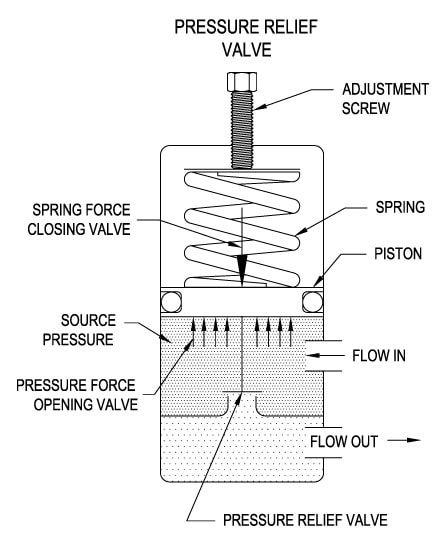
Below is an example of one of our pilot operated pressure relief valves in action; the cutaway demonstrates when high pressure is released from the system.
Air pressure relief valves can be applied to a variety of environments and equipment. Pressure relief valves are a safety valve used to keep equipment and the operators safe too. They"re instrumental in applications where proper pressure levels are vital for correct and safe operation. Such as oil and gas, power generation like central heating systems, and multi-phase applications in refining and chemical processing.
At Curtiss-Wright, we provide a range of different pressure relief valves based on two primary operations – spring-loaded and pilot operated. Spring-loaded valves can either be conventional spring-loaded or balanced spring-loaded.
Spring-loaded valves are programmed to open and close via a spring mechanism. They open when the pressure reaches an unacceptable level to release the material inside the vessel. It closes automatically when the pressure is released, and it returns to an average operating level. Spring-loaded safety valves rely on the closing force applied by a spring onto the main seating area. They can also be controlled in numerous ways, such as a remote, control panel, and computer program.
Pilot-operated relief valves operate by combining the primary relieving device (main valve) with self-actuated auxiliary pressure relief valves, also known as the pilot control. This pilot control dictates the opening and closing of the main valve and responds to system pressure. System pressure is fed from the inlet into and through the pilot control and ultimately into the main valve"s dome. In normal operating conditions, system pressure will prevent the main valve from opening.
The valves allow media to flow from an auxiliary passage and out of the system once absolute pressure is reached, whether it is a maximum or minimum level.
When the pressure is below the maximum amount, the pressure differential is slightly positive on the piston"s dome size, which keeps the main valve in the closed position. When system pressure rises and reaches the set point, the pilot will cut off flow to the dome, causing depressurization in the piston"s dome side. The pressure differential has reversed, and the piston will rise, opening the main valve, relieving pressure.
When the process pressure decreases to a specific pressure, the pilot closes, the dome is repressurized, and the main valve closes. The main difference between spring-loaded PRVs and pilot-operated is that a pilot-operated safety valve uses pressure to keep the valve closed.
Pilot-operated relief valves are controlled by hand and are typically opened often through a wheel or similar component. The user opens the valve when the gauge signifies that the system pressure is at an unsafe level; once the valve has opened and the pressure has been released, the operator can shut it by hand again.
Increasing pressure helps to maintain the pilot"s seal. Once the setpoint has been reached, the valve opens. This reduces leakage and fugitive emissions.
At set pressure the valve snaps to full lift. This can be quite violent on large pipes with significant pressure. The pressure has to drop below the set pressure in order for the piston to reseat.
The pilot is designed to open gradually, so that less of the system fluid is lost during each relief event. The piston lifts in proportion to the overpressure.
At Curtiss-Wright we also provide solutions for pressure relief valve monitoring. Historically, pressure relief valves have been difficult or impossible to monitor. Our SmartPRV features a 2600 Series pressure relief valve accessorized with a wireless position monitor that alerts plant operators during an overpressure event, including the time and duration.
There are many causes of overpressure, but the most common ones are typically blocked discharge in the system, gas blowby, and fire. Even proper inspection and maintenance will not eliminate the occurrence of leakages. An air pressure relief valve is the only way to ensure a safe environment for the device, its surroundings, and operators.
A PRV and PSV are interchangeable, but there is a difference between the two valves. A pressure release valve gradually opens when experiencing pressure, whereas a pressure safety valve opens suddenly when the pressure hits a certain level of over pressurization. Safety valves can be used manually and are typically used for a permanent shutdown. Air pressure relief valves are used for operational requirements, and they gently release the pressure before it hits the maximum high-pressure point and circulates it back into the system.
Pressure relief valves should be subject to an annual test, one per year. The operator is responsible for carrying out the test, which should be done using an air compressor. It’s imperative to ensure pressure relief valves maintain their effectiveness over time and are checked for signs of corrosion and loss of functionality. Air pressure relief valves should also be checked before their installation, after each fire event, and regularly as decided by the operators.
Direct-acting solenoid valves have a direct connection with the opening and closing armature, whereas pilot-operated valves use of the process fluid to assist in piloting the operation of the valve.
A control valve works by varying the rate of fluid passing through the valve itself. As the valve stem moves, it alters the size of the passage and increases, decreases or holds steady the flow. The opening and closing of the valve is altered whenever the controlled process parameter does not reach the set point.
Control valves are usually at floor level or easily accessible via platforms. They are also located on the same equipment or pipeline as the measurement and downstream or flow measurements.
An industrial relief valve is designed to control or limit surges of pressure in a system, most often in fluid or compressed air system valves. It does so as a form of protection for the system and defending against instrument or equipment failure. They are usually present in clean water industries.
A PRV is often referred to as a pressure relief valve, which is also known as a PSV or pressure safety valve. They are used interchangeably throughout the industry depending on company standards.

Industry leading pressure and safety relief valve designs with over 140 years of technical and application expertise providing custom engineered solutions for O&G, Refining, Chemical, Petrochemical, Process and Power applications. Our designs meet global and local codes and standards (API 526; ASME Section I, IV & VIII; EN ISO 4126; PED & more). Gain insight into the performance of your pressure relief valves with wireless monitoring.
A relief valve or pressure relief valve (PRV) is a type of safety valve used to control or limit the pressure in a system; pressure might otherwise build up and create a process upset, instrument or equipment failure, or fire. The pressure is relieved by allowing the pressurized fluid to flow from an auxiliary passage out of the system. The relief valve is designed or set to open at a predetermined set pressure to protect pressure vessels and other equipment from being subjected to pressures that exceed their design limits. When the set pressure is exceeded, the relief valve becomes the "path of least resistance" as the valve is forced open and a portion of the fluid is diverted through the auxiliary route. In systems containing flammable fluids, the diverted fluid (liquid, gas or liquid-gas mixture) is either recapturedvapor recovery system or is routed through a piping system known as a flare header or relief header to a central, elevated gas flare where it is burned, releasing naked combustion gases into the atmosphere.blowdown is usually stated as a percentage of set pressure and refers to how much the pressure needs to drop before the valve reseats. The blowdown can vary roughly 2–20%, and some valves have adjustable blowdowns.
In high-pressure gas systems, it is recommended that the outlet of the relief valve is in the open air. In systems where the outlet is connected to piping, the opening of a relief valve will give a pressure build-up in the piping system downstream of the relief valve. This often means that the relief valve will not re-seat once the set pressure is reached. For these systems often so-called "differential" relief valves are used. This means that the pressure is only working on an area that is much smaller than the area of the opening of the valve. If the valve is opened the pressure has to decrease enormously before the valve closes and also the outlet pressure of the valve can easily keep the valve open. Another consideration is that if other relief valves are connected to the outlet pipe system, they may open as the pressure in the exhaust pipe system increases. This may cause undesired operation.
In some cases, a so-called bypass valve acts as a relief valve by being used to return all or part of the fluid discharged by a pump or gas compressor back to either a storage reservoir or the inlet of the pump or gas compressor. This is done to protect the pump or gas compressor and any associated equipment from excessive pressure. The bypass valve and bypass path can be internal (an integral part of the pump or compressor) or external (installed as a component in the fluid path). Many fire engines have such relief valves to prevent the overpressurization of fire hoses.
In other cases, equipment must be protected against being subjected to an internal vacuum (i.e., low pressure) that is lower than the equipment can withstand. In such cases, vacuum relief valves are used to open at a predetermined low-pressure limit and to admit air or an inert gas into the equipment to control the amount of vacuum.
In the petroleum refining, petrochemical and chemical manufacturing, natural gas processing and power generation industries, the term relief valve is associated with the terms pressure relief valve (PRV), pressure safety valve (PSV) and safety valve:
Pressure relief valve (PRV) or Pressure Release valve (PRV) or pressure safety valve (PSV): The difference is that PSVs have a manual lever to activate the valve in case of emergency. Most PRVs are spring operated. At lower pressures some use a diaphragm in place of a spring. The oldest PRV designs use a weight to seal the valve.
Set pressure: When the system pressure increases to this value, the PRV opens. The accuracy of the set pressure may follow guidelines set by the American Society of Mechanical Engineers (ASME).
Safety relief valve (SRV): A relief valve that can be used for gas or liquid service. However, the set pressure will usually only be accurate for one type of fluid at a time.
Pilot-operated relief valve (POSRV, PORV, POPRV): A device that relieves by remote command from a pilot valve which is connected to the upstream system pressure.
Low-pressure safety valve (LPSV): An automatic system that relieves by the static pressure of a gas. The relieving pressure is small and near the atmospheric pressure.
Vacuum pressure safety valve (VPSV): An automatic system that relieves by the static pressure of a gas. The relieving pressure is small, negative, and near the atmospheric pressure.
Low and vacuum pressure safety valve (LVPSV): An automatic system that relieves by the static pressure of a gas. The relieving pressure is small, negative, or positive, and near the atmospheric pressure.
Pressure vacuum release valve (PVRV): A combination of vacuum pressure and a relief valve in one housing. Used on storage tanks for liquids to prevent implosion or overpressure.
Snap acting: The opposite of modulating, refers to a valve that "pops" open. It snaps into a full lift in milliseconds. Usually accomplished with a skirt on the disc so that the fluid passing the seat suddenly affects a larger area and creates more lifting force.
In most countries, industries are legally required to protect pressure vessels and other equipment by using relief valves. Also in most countries, equipment design codes such as those provided by the American Society of Mechanical Engineers (ASME), American Petroleum Institute (API) and other organizations like ISO (ISO 4126) must be complied with and those codes include design standards for relief valves.
Formed in 1977, the Design Institute for Emergency Relief SystemsAIChE) that developed methods for the design of emergency relief systems to handle runaway reactions. Its purpose was to develop the technology and methods needed for sizing pressure relief systems for chemical reactors, particularly those in which exothermic reactions are carried out. Such reactions include many classes of industrially important processes including polymerizations, nitrations, diazotizations, sulphonations, epoxidations, aminations, esterifications, neutralizations, and many others. Pressure relief systems can be difficult to design, not least because what is expelled can be gas/vapor, liquid, or a mixture of the two – just as with a can of carbonated drink when it is suddenly opened. For chemical reactions, it requires extensive knowledge of both chemical reaction hazards and fluid flow.
DIERS investigated the two-phase vapor-liquid onset/disengagement dynamics and the hydrod


 8613371530291