
how many safety valve in boiler manufacturer

Years ago, it was not uncommon to read news about tragic boiler explosions, sometimes resulting in mass destruction. Today, boilers are equipped with important safety devises to help protect against these types of catastrophes. Let’s take a look at the most critical of these devices: the safety valve.
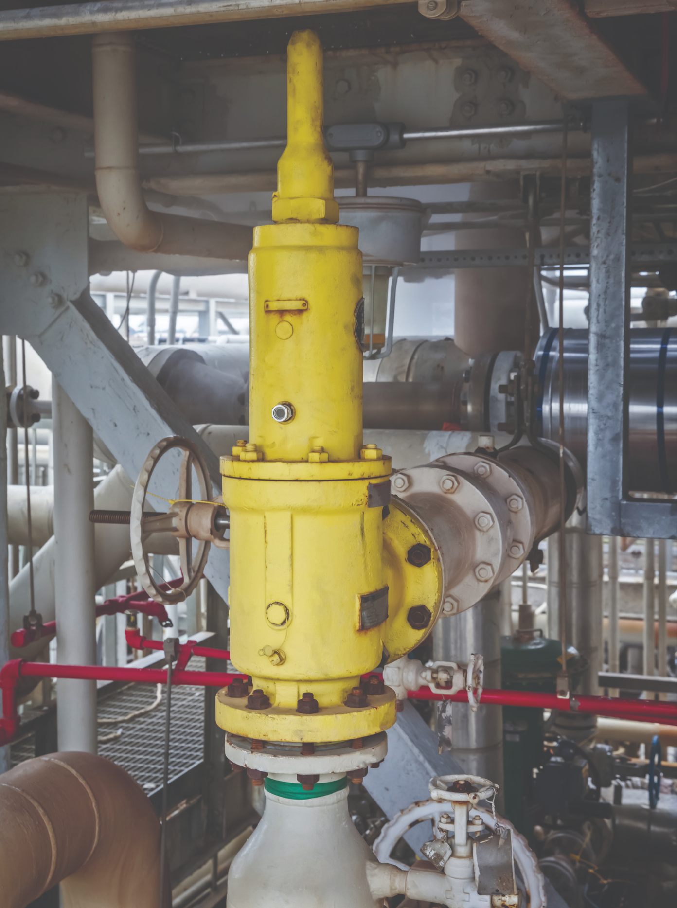
The safety valve is one of the most important safety devices in a steam system. Safety valves provide a measure of security for plant operators and equipment from over pressure conditions. The main function of a safety valve is to relieve pressure. It is located on the boiler steam drum, and will automatically open when the pressure of the inlet side of the valve increases past the preset pressure. All boilers are required by ASME code to have at least one safety valve, dependent upon the maximum flow capacity (MFC) of the boiler. The total capacity of the safety valve at the set point must exceed the steam control valve’s MFC if the steam valve were to fail to open. In most cases, two safety valves per boiler are required, and a third may be needed if they do not exceed the MFC.
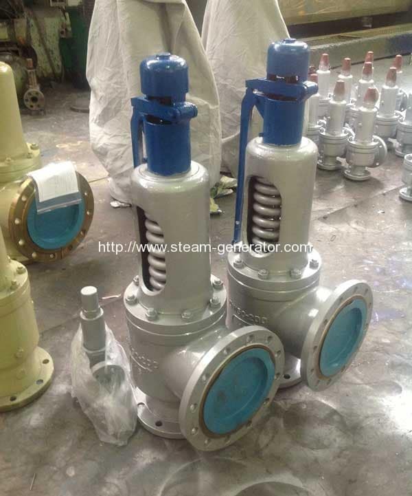
There are three main parts to the safety valve: nozzle, disc, and spring. Pressurized steam enters the valve through the nozzle and is then threaded to the boiler. The disc is the lid to the nozzle, which opens or closes depending on the pressure coming from the boiler. The spring is the pressure controller.
As a boiler starts to over pressure, the nozzle will start to receive a higher pressure coming from the inlet side of the valve, and will start to sound like it is simmering. When the pressure becomes higher than the predetermined pressure of the spring, the disc will start to lift and release the steam, creating a “pop” sound. After it has released and the steam and pressure drops below the set pressure of the valve, the spring will close the disc. Once the safety valve has popped, it is important to check the valve to make sure it is not damaged and is working properly.
A safety valve is usually referred to as the last line of safety defense. Without safety valves, the boiler can exceed it’s maximum allowable working pressure (MAWP) and not only damage equipment, but also injure or kill plant operators that are close by. Many variables can cause a safety valve on a boiler to lift, such as a compressed air or electrical power failure to control instrumentation, or an imbalance of feedwater rate caused by an inadvertently shut or open isolation valve.
Once a safety valve has lifted, it is important to do a complete boiler inspection and confirm that there are no other boiler servicing issues. A safety valve should only do its job once; safety valves should not lift continuously. Lastly, it is important to have the safety valves fully repaired, cleaned and recertified with a National Board valve repair (VR) stamp as required by local code or jurisdiction. Safety valves are a critical component in a steam system, and must be maintained.
All of Nationwide Boiler’s rental boilers include on to two safety valves depending on the size; one set at design pressure and the other set slightly higher than design. By request, we can reset the safeties to a lower pressure if the application requires it. In addition, the valves are thoroughly checked after every rental and before going out to a new customer, and they are replaced and re-certified as needed.
Cast-iron boilers may be used in steam heating or hot water heating applications within the scope and service restrictions of ASME BPV Code Section IV. ASME BPV Code Section IV service restrictions limit steam boilers to pressures not exceeding 15 psi and hot water boilers to pressures not exceeding 160 psi and/or temperatures not exceeding 250°F.
Vertical Sectional– made up of individual cast iron sections assembled so the sections resemble slices in a loaf of bread. This is probably the most common configuration.
One Piece – a single casting with no assembly joints. Another term used to describe this design is monobloc. This type of cast-iron boiler is usually small in size.
Sectional boilers are typically assembled with tapered connections called push nipples or elastomeric-type gaskets between the sections to seal the water-containing chambers. Another type of assembly uses external headers to connect the water containing chambers.
Cast-iron boilers can be found in almost any application where heating boilers are used. They are popular replacements for large welded steel boilers which may have been installed as the building was being constructed. Cast-iron sectional boilers can usually be installed in existing boiler rooms by moving the individual sections through doors or window openings. A very large boiler can be assembled in this manner without modifications to the building structure.
There will be two pieces of information missing from a cast-iron boiler nameplate: a National Board registration number and the year built. Cast-iron boilers are not registered with the National Board, and ASME BPV Code Section IV makes no provisions for a year of construction to appear on the nameplate. Since most inspection forms ask for a year of construction, the inspector will have to estimate. If the boiler is original to the building, the age of the building would directly correspond to the age of the boiler. If the boiler is a replacement, the inspector will have to question the owner to determine its age.
Cast-iron boilers may be used in steam heating or hot water heating applications within the scope and service restrictions of ASME BPV CodeSection IV. ASME BPV CodeSection IV service restrictions limit steam boilers to pressures not exceeding 15 psi and hot water boilers to pressures not exceeding 160 psi and/or temperatures not exceeding 250°F.
Steam boilers must have at least one safety valve with a set pressure not to exceed 15 psi. The safety valve inlet must not be smaller than NPS 1/2 nor larger than NPS 4-1/2.
Hot-water boilers must have at least one safety relief valve with a set pressure at or below the maximum allowable working pressure (MAWP) marked on the boiler. The safety relief valve inlet must not be smaller than NPS 3/4 nor larger than NPS 4-1/2. The minimum relieving capacity of safety or safety relief valves must equal or exceed the maximum output of the boiler. Cast-iron boilers constructed since 1943 will have information on the nameplate indicating the minimum required safety or safety relief valve capacity. Cast-iron boilers constructed prior to 1943 may not have that information. In those circumstances, the inspector must estimate the maximum output of the boiler. Gas or oil burners generally have a rating plate or label containing the Btu output of the burner. A generally applied guideline for older boilers is to use 80% of the maximum burner output as the maximum boiler output. Boilers fired with solid fuel such as coal or wood will be extremely difficult to estimate, since there is no way for the inspector to calculate the cast-iron boiler heating surface. In those cases, the inspector should request the boiler owner/user perform an accumulation test in accordance with HG-512(a), or a maximum burned fuel evaluation in accordance with HG-512(b) and Appendix B. These procedures should only be used if the safety or safety relief valve capacity is in doubt.
two pressure controls (if the boiler is automatically fired); one is considered the operating control and the other is considered the high-limit control (Note: some jurisdictions require the high-limit control be equipped with a manual reset switch) (HG-605);
an automatic low-water fuel cutoff – if the boiler is automatically fired (Note: some jurisdictions require an additional low-water fuel cutoff with a manual reset switch) (HG-606).
two temperature controls (if the boiler is automatically fired); one is considered the operating control and the other is considered the high-limit control (Note: some jurisdictions require the high limit control be equipped with a manual reset switch) (HG-613);
an automatic low-water fuel cutoff – if the boiler is automatically fired and has a heat input greater than 400,000 Btu/hr (Note: some jurisdictions require an additional low water fuel cutoff with a manual reset switch)(HG-614)
Clearances on the front, rear, sides, and top of all cast-iron boilers for operation, maintenance, and inspection shall meet jurisdictional requirements. If no jurisdictional requirements exist, then the boiler manufacturer"s requirements shall be met.
All cast-iron boilers should be installed on foundations or supports suitable for the weight of the boiler and its contents. The foundation or support must also be unaffected by the heat of the operating boiler.
Although most jurisdictions do not require inspection of the piping associated with an ASME BPV CodeSection IV boiler, there are some installation requirements in ASME BPV Code Section IV the inspector should review. Please see HG-703 and HG-705.
Steam boilers must have at least one safety valve with a set pressure not to exceed 15 psi. The safety valve inlet must not be smaller than NPS 1/2 nor larger than NPS 4-1/2.
Cast-iron boilers typically have a few inherent problems. The inspector should always look for water leaks at the connecting joints of sectional boilers. The inspector should request the removal of the sheet metal casing any time there is evidence of leakage and the leakage cannot be traced to an external source.
The most common problem associated with cast-iron boilers is cracking due to overheating or thermal shock. Overheating occurs when the boiler is allowed to operate with low-water conditions or poor circulation caused by sludge concentrated in the lower water passages of the boiler. Thermal shock can occur when a boiler is overheated and cold water is added in an attempt to raise the water level. Under those circumstances, cracking is usually the least that can happen. The worst that can happen is an explosion which shatters the cast-iron boiler into many pieces and cause destruction and injury.
Sectional cast-iron boilers use long rods, threaded on both ends, called draw bolts. It is not unusual for these draw bolts to appear loose when the boiler is cold. When the boiler is operating, the heat will cause the boiler to expand which tightens the draw bolts. A loose draw bolt on a hot boiler should be investigated by a competent cast-iron boiler service/repair company.
Cast-iron boilers typically have a few inherent problems. The inspector should always look for water leaks at the connecting joints of sectional boilers. The inspector should request the removal of the sheet metal casing any time there is evidence of leakage and the leakage cannot be traced to an external source.
Upon entering the boiler room, the inspector should perform a general assessment of the boiler, piping, controls, fuel system, and combustion air supply. The inspector should then:
compare the safety or safety relief valve nameplate data (set pressure and relieving capacity) with the boiler nameplate to ensure the safety or safety relief valve is adequate for this installation;
inspect the low-water fuel cutoff and water feeding device (if applicable) as described in the National Board Inspector Guide for Water Level Controls and Devices;
check the thermometer reading on hot water boilers (if there is a reason to question the accuracy of the thermometer, it should be replaced or recalibrated);
check the water gage glass to ensure it provides a clear indication of the water level in a steam boiler. (Please see the National Board Inspector Guide for Water Level Controls and Devices);
instruct the owner or owner"s representative to repair any leaks which may have been discovered (if a leak is detected as a result of a crack in the cast iron, there is no acceptable repair except replacement of the cracked section);
look for evidence of overheating (this may be difficult to detect on a cast-iron boiler; warped external sheet metal casings with scorched paint is usually a reliable indicator);
inspect the fuel-burning apparatus as required by the jurisdiction (for example, some jurisdictions mandate compliance with ASME Standard CSD-1, Controls & Safety Devices for Automatically Fired Boilers).
Internal inspections of cast-iron boilers can prove to be difficult or almost impossible. Threaded plugs on the cast iron boiler could be removed, but the inspector will see very little past the immediate vicinity of the opening on many cast iron boiler designs. In addition, the threaded plugs are sometimes heavily corroded which virtually "welds" them to the cast iron. Removal of threaded plugs in this condition may damage the cast iron irreparably. Some boilers may have valves installed in the lowest threaded openings of the boiler to facilitate draining and/or flushing of the boiler. If valves are present, the inspector can ask for them to be opened briefly to observe the condition of the water. If no water is present when the valves are opened, this could be an indication the lowest portion of the boiler is filled with sludge. The inspector is advised to follow the jurisdiction"s requirements for internal inspections of cast-iron boilers.
Float-type low-water fuel cutoffs and water-feeding devices (if applicable) must be disassembled so the inspector can observe the condition of the float, float mechanism, and the float chamber.
Threaded plugs in the piping connecting a water gage glass, water column, and low-water fuel cutoff to a steam boiler must be removed to allow inspection of the piping to ensure there is no blockage.

Operating controls for boilers could be broadly defined to include burner management controls; however, this inspector guide will be limited to the pressure and temperature operating controls required by the ASME BPV Code for steam and hot water boilers.
Steam boilers require a device which senses steam pressure and cycles the burner or other source of heat in order to maintain a consistent, predetermined operating pressure. A second device is used to prevent the boiler from exceeding the maximum allowable working pressure (MAWP) indicated on the boiler nameplate.
Hot-water boilers require a device which senses water temperature and cycles the burner or other source of heat in order to maintain a consistent, predetermined operating temperature. A second device is used to prevent the boiler from exceeding the design temperature of an ASME BPV Code Section I boiler or the maximum water temperature indicated on an ASME BPV Code Section IV boiler nameplate.
The secondary device referenced above for both steam and hot-water boilers is referred to as a high-limit control and under normal conditions, would never be called upon to operate. However, if the primary, or operating, control should fail, the high-limit control must operate, stopping the burner or other source of heat. Some high-limit controls incorporate a manual reset. The purpose of this is to alert the operator that the high-limit control has been activated. The operator should then look for the problem which caused the high-limit control to activate before resetting the device and restarting the boiler.
ASME BPV Code Section I does not specifically mandate pressure or temperature controls but they will be found, in one form or another, on almost all ASME BPV Code Section I boilers. In addition, ASME Standard CSD-1 (if applicable) requires the controls on boilers with input ratings up to 12,500,000 Btu/hr. Jurisdictional regulations will specify the use of ASME Standard CSD-1 if it is mandated.
A pressure control must be installed so as to always sense pressure from the steam space of the boiler. The ASME BPV Code requirements and device manufacturer"s instructions should be followed for any installation details. When a siphon or pigtail is used to prevent live steam from entering and damaging the device, the orientation of the siphon loop is critical to the proper operation of a device containing a mercury switch. If the siphon loop is installed in the incorrect orientation shown in Figure 1, movement of the loop caused by heat and/or pressure can cause the mercury switch in the device to activate or deactivate at other than the set pressure.
A temperature control must be installed as required by the ASME BPV Code and the manufacturer"s instructions. Temperature controls are designed and manufactured in different configurations to sense temperature on the surface of a pipe (sometimes called a surface mount device), in a thermo-well, or directly in the water.
Either type of operating control can be bypassed electrically with jumper wires. Jumper wires can be used legitimately by qualified service personnel during maintenance and testing, but must be removed before returning the boiler to normal operation. Jumper wires could be used inappropriately in an attempt to permanently bypass a control which has malfunctioned and will not allow the boiler to operate.
While inspecting low-pressure or high-pressure boilers, the inspector will be observing operating controls. The inspector must take the time necessary to completely evaluate the condition and operational effectiveness of these controls. The inspector should:
Compare the pressure gage reading on a steam boiler with the set pressure of the primary operating control. If the pressure gage reading is higher than the set pressure of the control, request the installation of a second, reliable pressure gage in order to determine the accuracy of the first pressure gage. If the second pressure gage reading agrees with the operating control set pressure, the first pressure gage must be recalibrated or replaced. If, however, the second pressure gage reading agrees with the first pressure gage, the boiler should be removed from service until the primary operating control can be repaired or replaced.
Compare the thermometer reading on a hot-water boiler with the set temperature of the primary operating control. If the thermometer reading is higher than the set temperature of the control, request the installation of a second, reliable thermometer in order to determine the accuracy of the first thermometer. If the second thermometer reading agrees with the operating control set temperature, the first thermometer must be recalibrated or replaced. If, however, the second thermometer reading agrees with the first thermometer, the boiler should be removed from service until the primary operating control can be repaired or replaced
Request the owner or owner"s representative test the high-limit control in accordance with the control manufacturer"s instructions. This test may involve disabling the primary operating control or setting the primary control"s pressure or temperature, as applicable, higher than the setting of the high-limit control. Since each installation can be unique, the inspector should rely on the control manufacturer"s instructions for guidance. Before returning the boiler to its normal operating condition, ensure all operating controls are enabled and set to the proper pressure or temperature.
Additional information to aid inspections of operating controls, including installation requirements, can be found in the following publications and sources:
This website is using a security service to protect itself from online attacks. The action you just performed triggered the security solution. There are several actions that could trigger this block including submitting a certain word or phrase, a SQL command or malformed data.

Boiler explosions have been responsible for widespread damage to companies throughout the years, and that’s why today’s boilers are equipped with safety valves and/or relief valves. Boiler safety valves are designed to prevent excess pressure, which is usually responsible for those devastating explosions. That said, to ensure that boiler safety valves are working properly and providing adequate protection, they must meet regulatory specifications and require ongoing maintenance and periodic testing. Without these precautions, malfunctioning safety valves may fail, resulting in potentially disastrous consequences.
Boiler safety valves are activated by upstream pressure. If the pressure exceeds a defined threshold, the valve activates and automatically releases pressure. Typically used for gas or vapor service, boiler safety valves pop fully open once a pressure threshold is reached and remain open until the boiler pressure reaches a pre-defined, safe lower pressure.
Boiler relief valves serve the same purpose – automatically lowering boiler pressure – but they function a bit differently than safety valves. A relief valve doesn’t open fully when pressure exceeds a defined threshold; instead, it opens gradually when the pressure threshold is exceeded and closes gradually until the lower, safe threshold is reached. Boiler relief valves are typically used for liquid service.
There are also devices known as “safety relief valves” which have the characteristics of both types discussed above. Safety relief valves can be used for either liquid or gas or vapor service.
Nameplates must be fastened securely and permanently to the safety valve and remain readable throughout the lifespan of the valve, so durability is key.
The National Board of Boiler and Pressure Vessel Inspectors offers guidance and recommendations on boiler and pressure vessel safety rules and regulations. However, most individual states set forth their own rules and regulations, and while they may be similar across states, it’s important to ensure that your boiler safety valves meet all state and local regulatory requirements.
The National Board published NB-131, Recommended Boiler and Pressure Vessel Safety Legislation, and NB-132, Recommended Administrative Boiler and Pressure Vessel Safety Rules and Regulationsin order to provide guidance and encourage the development of crucial safety laws in jurisdictions that currently have no laws in place for the “proper construction, installation, inspection, operation, maintenance, alterations, and repairs” necessary to protect workers and the public from dangerous boiler and pressure vessel explosions that may occur without these safeguards in place.
The documents are meant to be used as a guide for developing local laws and regulations and also may be used to update a jurisdiction’s existing requirements. As such, they’re intended to be modifiable to meet any jurisdiction’s local conditions.
The American Society of Mechanical Engineers (ASME) governs the code that establishes guidelines and requirements for safety valves. Note that it’s up to plant personnel to familiarize themselves with the requirements and understand which parts of the code apply to specific parts of the plant’s steam systems.
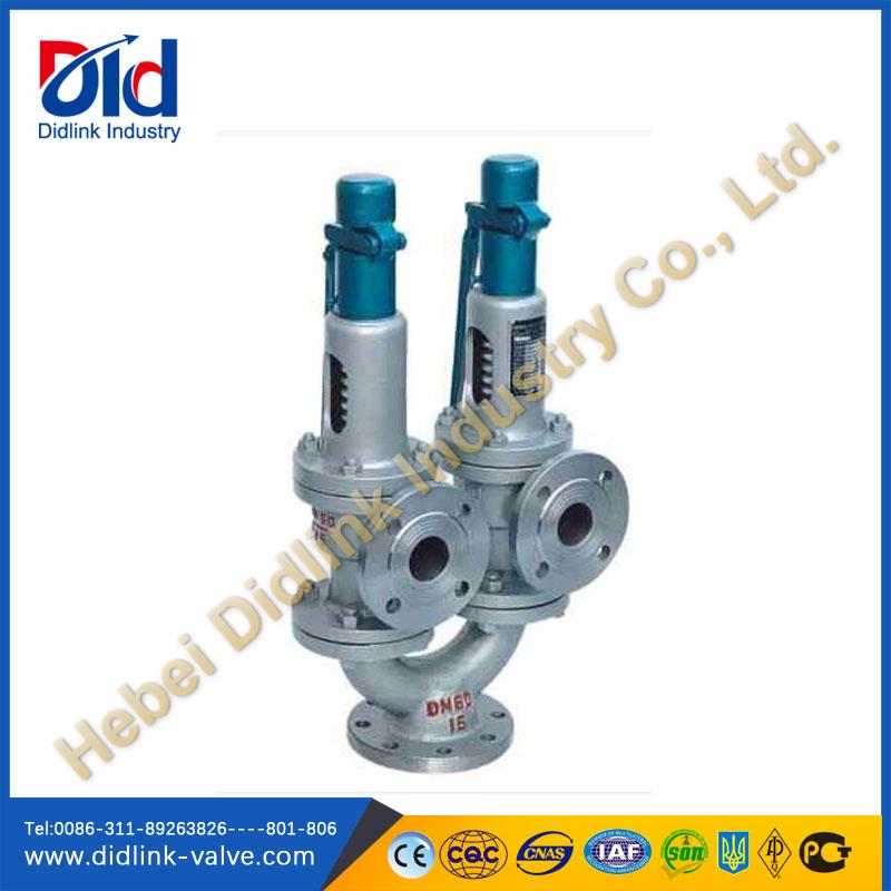
High steam capacity requirements, physical or economic constraints may make the use of a single safety valve impossible. In these cases, using multiple safety valves on the same system is considered an acceptable practice, provided that proper sizing and installation requirements are met – including an appropriately sized vent pipe that accounts for the total steam venting capacity of all valves when open at the same time.
The lowest rating (MAWP or maximum allowable working pressure) should always be used among all safety devices within a system, including boilers, pressure vessels, and equipment piping systems, to determine the safety valve set pressure.
General guidance on proper installation may seem like common sense to experienced installers and inspectors. A few of the most important guidelines and best practices include:
Avoid isolating safety valves from the system, such as by installing intervening shut-off valves located between the steam component or system and the inlet.
Contact the valve supplier immediately for any safety valve with a broken wire seal, as this indicates that the valve is unsafe for use. Safety valves are sealed and certified in order to prevent tampering that can prevent proper function.
Avoid attaching vent discharge piping directly to a safety valve, which may place unnecessary weight and additional stress on the valve, altering the set pressure.
Steam boilers first came into light in the 17th century, wherein boilers were kettle-type that functioned by placing water above a firebox to generate steam. As the years progressed, the design and construction of steam boilers were enhanced and upgraded as they were used in industries and ships or locomotives. However, it also resulted in boiler explosions at an alarming rate that took place frequently, causing loss of lives and production. It led to the increasing need for safety measures to be taken while manufacturing a steam boiler. After years of work, safety valves were invented and installed in steam boilers in order to protect life and property during industrial process operations.
The first-ever safety valve was invented in 1707 by Denis Papin and was installed in his steam digester that seemed to be as a pressure cooker rather than a steam boiler. Safety valves in the early years were manufactured with great caution. After a hazardous explosion, Richard Trevithick started installing a pair of safety valves in the boilers by 1806. These safety valves were not adjustable, released high pressure, and would continuously leak the waste steam. With the passing years, engineers began to invent safety valves of different types that were highly efficient in safeguarding the process plant and the lives of operating staff. Presently, safety valves are essential in every steam boiler by most countries and organizations including ISO 4126, ASME, API, and various others. Most of the safety valves are manufactured with stainless steel, used in a boiler system for various industries such as pharmaceutical, food processing, chemicals, and many more.
Safety valves are generally located on the steam drum of the boiler and open automatically when the inlet-side pressure of the valves exceeds the predetermined pressure. There are three main components of a safety valve: disc, nozzle, and spring. The total capacity of the safety valve must be more than the maximum flow capacity (MFC) of the safety valve in case steam valves fail to open. Most steam boilers connect two safety valves in it, but it may require a third safety valve if it does not exceed the MFC.
There are several types of safety valves that perform differently. In countries like India and America, spring-loaded safety valves are used extensively along with torsion bar safety valves. Let us have a look at different safety valves in detail.
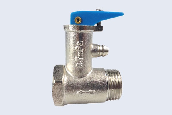
Spring-loaded safety valves, also known as pressure relief valves, are the most commonly used safety valves in most countries. It is designed in a way to compel the load of the steam to press the disc against the inlet pressure. Different boilers require different safety valves depending on the type of fluid.
Pilot operated pressure relief valves consist of the main valve and pilot assy. In the case of spring-loaded pressure relief valves, it uses the force of the spring for the inlet pressure. However, in pilot-operated pressure relief valves, the reseating and reliving of pressure is performed by the pilot assy. Although there is a lack of adjusting facility, pilot-operated pressure relief valves have variations in a larger size suitable for high-pressure conditions.
The pressure vessel is set at very low pressure in the design pressure of dead-weight pressure relief valves. Such safety valves release pressure by adjusting the disc weight. These characteristics are also found in vacuum relief valves that extract the pressure as the pressure vessel falls into negative pressure.
The overpressure in boilers results in the nozzle receiving higher pressure from the inlet of the valves that begins to make boiling or simmering sounds. When the pressure exceeds the predetermined spring pressure, the disc starts lifting and releasing the steam with a popping sound. Once the steam is released, leading to a drop in steam and pressure, the spring closes the disc. It is vital to frequently check the steam valves to ensure it is undamaged and functions efficiently.
Boiler relief, however, functions in a slightly different manner than safety valves by opening gradually as the pressure increases rather than opening fully as in safety valves. Similar to its way of opening, boiler relief closes gradually after the pressure limit is reduced and is mostly used for liquid vapor.
Since its formation in 1983, Rakhoh Boilers strives to enhance and improve the safety of the boiler operations by manufacturing and installing boiler safety valves of the highest quality that ensure the safety of the process plants and prevent any fatal accidents or injuries to the staff working and operating the plant.

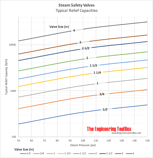
Each boiler (including exhaust gas boiler) and steam generator is to be fitted with at least one safety valve and where the water-heating surface is more than 46.5 m2(500 ft2), two or more safety valves are to be provided. The valves are to be of equal size as far as practicable and their aggregate relieving capacity is not to be less than the evaporating capacity of the boiler under maximum operating conditions.
- is the inlet diameter of any safety valve for propulsion boiler and superheaters used to generate steam for main propulsion and other machinery to be less than 38 mm (1.5 in.) nor more than 102 mm (4 in.).
- For auxiliary boilers and exhaust gas economizers, the inlet diameter of the safety valve must not be less than 19 mm (3/4 in.) nor more than 102 mm (4 in.).
Each superheater, regardless of whether it can be isolated from the boiler or not, is to be fitted with at least one safety valve on the superheater outlet.
Each economizer, where fitted with a bypass, is to be provided with a sentinel relief valve, unless the bypass arrangement will prevent a buildup of pressure in the economizer when it is
In all cases, the safety-valve relieving capacity is to be determined on the basis of the boiler heating surface and water-wall heating surface along with the fuel-burning equipment, and is not to be less than that given in the table(see later).
Where certification by the boiler manufacturer of the evaporative capacity of the boiler under maximum operating conditions indicates a higher capacity, the higher capacity isto be used.
Where a superheater is fitted as an integral part of a boiler with no intervening valve between the superheater and the boiler, the relieving capacity of the superheater safety valve, based on the reduced pressure, may be included in determining the total relieving capacity of the safety valvesfor the boiler as a whole.
The safety valves are to be so set and proportioned that, under any relieving condition, sufficient steam will pass through the superheater to preventoverheating the superheater.
For each boiler, the total capacity of the installed safety valves is to be such that the valves will discharge all steam that can be generated by the boiler without allowing the pressure to rise more than 6% above the maximum allowable workingpressure.
If more than one safety valve is installed, the highest setting among the safety valves is not to exceed the maximum allowable workingpressure by more than 3%.
The range of pressure settings of all the drum safety valves is not toexceed 10% of the highest pressure to which any safety valve is setIn no case is the relief pressure to be greater than the design pressure of the steam piping or that of the machinery connected tothe boiler plus the pressure drop in the steam piping.
Where a superheater is fitted, the superheater safety valve is to beset to relieve at a pressure no greater than the design pressure of thesteam piping or the design pressure of the machinery connected tothe superheater plus pressure drop in the steam piping.
In connection with the superheater, the safety valves on the boiler drum are to be set at a pressure not less than the superheater-valve setting plus 0.34 bar (0.35 kgf/cm2, 5 psi), plus approximately thenormal-load pressure drop through the superheater.
Each boiler and superheater safety valve is to be fitted with an efficient mechanical means by which the valvedisc may be positively lifted from its seat.
This mechanism is to be so arranged that the valves may be safely operated from the boiler room or machinery space platforms, either by hand or by anyapproved power arrangement.
The pipe is to be so routed as to prevent the accumulation of condensate and is to be so supported that the body of the safety valve is not subjected toundue load or moment.
The boiler pressure is not to rise more than 6% above the maximum allowable working pressure when the steam stop valve is closed under full firing condition for a duration of 15 minutes forfiretube boilers and 7 minutes for watertube boilers.
Where such accumulation tests are impractical because of superheaterdesign, an application to omit such tests may be approved, provided the following are complied with:
- The valve manufacturer supplies a certificate for each safety valve stating its capacity at the maximum allowable working pressure and temperature of the boiler.
Where, for any reason, the maximum allowable working pressure is lower than that for which the boiler and safety valves were originally designed, the relieving capacity of the valves under lower pressure is to be checked against theevaporating capacity of the boiler.
For this purpose, a guarantee from the manufacturer that the valve capacity is sufficient for the new conditions is to be submitted for approval, or it is to be demonstrated by a pressure accumulation test, conducted in the presence of aSurveyor.

(1) Boiler safety valves and safety relief valves must be as indicated in PG-67 through PG-73 of section I of the ASME Boiler and Pressure Vessel Code (incorporated by reference; see 46 CFR 52.01-1) except as noted otherwise in this section.
(3) On river steam vessels whose boilers are connected in batteries without means of isolating one boiler from another, each battery of boilers shall be treated as a single boiler and equipped with not less than two safety valves of equal size.
(4) (Modifies PG-70.) The total rated relieving capacity of drum and superheater safety valves as certified by the valve manufacturer shall not be less than the maximum generating capacity of the boiler which shall be determined and certified by the boiler manufacturer. This capacity shall be in compliance with PG-70 of section I of the ASME Boiler and Pressure Vessel Code.
(5) In the event the maximum steam generating capacity of the boiler is increased by any means, the relieving capacity of the safety valves shall be checked by an inspector, and, if determined to be necessary, valves of increased relieving capacity shall be installed.
(6) (Modifies PG-67.) Drum safety valves shall be set to relieve at a pressure not in excess of that allowed by the Certificate of Inspection. Where for any reason this is lower than the pressure for which the boiler was originally designed and the revised safety valve capacity cannot be recomputed and certified by the valve manufacturer, one of the tests described in PG-70(3) of section I of the ASME Boiler and Pressure Vessel Code shall be conducted in the presence of the Inspector to insure that the relieving capacity is sufficient at the lower pressure.
(8) Lever or weighted safety valves now installed may be continued in use and may be repaired, but when renewals are necessary, lever or weighted safety valves shall not be used. All such replacements shall conform to the requirements of this section.
(10) (Modifies PG-73.2.) Cast iron may be used only for caps and lifting bars. When used for these parts, the elongation must be at least 5 percent in 51mm (2 inch) gage length. Nonmetallic material may be used only for gaskets and packing.
(1) (Modifies PG-68.) Superheater safety valves shall be as indicated in PG-68 of section I of the ASME Boiler and Pressure Vessel Code except as noted otherwise in this paragraph.
(2) The setting of the superheater safety valve shall not exceed the design pressure of the superheater outlet flange or the main steam piping beyond the superheater. To prevent damage to the superheater, the drum safety valve shall be set at a pressure not less than that of the superheater safety valve setting plus 5 pounds minimum plus approximately the normal load pressure drop through the superheater and associated piping, including the controlled desuperheater if fitted. See also § 52.01-95(b) (1).
(3) Drum pilot actuated superheater safety valves are permitted provided the setting of the pilot valve and superheater safety valve is such that the superheater safety valve will open before the drum safety valve.
(1) (Modifies PG-71.) Safety valves shall be installed as indicated in PG-71 of section I of the ASME Boiler and Pressure Vessel Code except as noted otherwise in this paragraph.
(2) The final setting of boiler safety valves shall be checked and adjusted under steam pressure and, if possible, while the boiler is on the line and the steam is at operating temperatures, in the presence of and to the satisfaction of a marine inspector who, upon acceptance, shall seal the valves. This regulation applies to both drum and superheater safety valves of all boilers.
(3) The safety valve body drains required by PG-71 of section I of the ASME Boiler and Pressure Vessel Code shall be run as directly as possible from the body of each boiler safety valve, or the drain from each boiler safety valve may be led to an independent header common only to boiler safety valve drains. No valves of any type shall be installed in the leakoff from drains or drain headers and they shall be led to suitable locations to avoid hazard to personnel.
(1) (Modifies PG-72.) The operation of safety valves shall be as indicated in PG-72 of section I of the ASME Boiler and Pressure Vessel Code except as noted in paragraph (d)(2) of this section.
(2) (Modifies PG-73.) The lifting device required by PG-73.1.3 of section I of the ASME Boiler and Pressure Vessel Code shall be fitted with suitable relieving gear so arranged that the controls may be operated from the fireroom or engineroom floor.

A safety valve is designed to open and relieve excess pressure from the boiler by releasing a volume of fluid from within the equipment when predetermined excess pressure is reached.
SThe safety valve is the most important safety fitting as it is fitted to prevent excessive pressure buildup in the boiler. Excessive pressure can lead to the boiler explosion. According to FMA regulation 1970, every boiler having a heating surface surpassing 100 square feet must be equipped with two safety valves. One of the safety valves must be of direct spring loaded type mounted vertically. The relieving capacity is determined by boiler capacity at peak load. Safety valve must be set to blow at different pressures. The spindles, moving parts & disk must not be made of the material that corrodes easily. The safety valve must be able to discharge steam pressure with a rise of pressure of not greater than 10% of authorized safe working pressure.
Thermodyne Engineering Systems is one of the best Industrial boiler manufacturing company in India. The process industry depends on the heat transfer equipment like Steam Boilers to get the job done, every day. So when you need a trustworthy manufacturer you can call us at +91-9891042944, +91-9990212122. Our goal is to ensure your system’s safety, maximize your efficiency and minimize your downtime. When you call our trained service technicians, you are calling for outstanding service to keep your boiler in top health. For any queries mail us at: sales1@thermodyneboilers.com

Boilers play a vital role in keeping most industrial facilities operating, so maintaining the efficiency and safety of this equipment is important. Thanks to new improvements in design and control systems, today’s boiler systems are safer than they have ever been. The following are three key safety devices that industrial boiler operators should understand and monitor.
One of the most important safety devices on an industrial boiler is the safety valve. There are a range of failures that can occur within the system that could cause the boiler to build up internal pressure. Safety valves are designed to relieve that pressure. There are usually two to six safety valves in the drum of an industrial boiler, depending on its capacity. The superheater outlet will generally have one to three valves on either side as well, and one electromatic relief valve on the superheater pipe. There should also be safety valves at the inlet and outlet sides of the reheater pipes.
Safety valves are simple in design and fairly straightforward in operation. Operators should be vigilant in keeping the valves clean and maintained. If corrosion builds up within the valve and restricts flow, the boiler’s pipes could be affected. If you are not able to maintain your entire system of valves, a local plumbing company experienced with industrial boiler systems can help.
Although they are separate boiler safety functions, water level control and low-water fuel cutoff controls are often combined into one device. The water level control and low-water fuel cutoff functions are designed to keep the water level inside the boiler from falling below a predetermined amount. If the water level falls below the minimum, these safety devices will effectively shut down the boiler by cutting off its fuel source. Industrial boiler operators should ensure sludge or scale does not build up within this safety system so that nothing interferes with its detection and operation.
Though boilers come equipped with safety devices that measure the water level, operators must still verify the actual level of the water inside the system. This is another instance where build-up of sludge and scale can produce false level indications.
Some industrial boilers do not have an automatic water feeder. In these systems, the water level needs to be checked at least once a week to ensure safe operation. If the water level is too low, it can lead to loss of heat or conditions that could even cause an explosion. If the water level is too high, it can prevent the steam from rising in an efficient manner.
As technology improves, the safe operation of industrial boilers has become easier than ever before. However, operators should not rely on design alone. It is important that boilers be regularly inspected, tested, and maintained for the unit’s entire lifespan.
A total industrial boiler system assessment, along with any necessary upgrades to safety devices, can save you money through improved efficiency and reduced frequency of repairs. If you are looking for the best local plumbing company to handle your industrial, commercial, or residential needs, contact the professionals at Allen’s Tri-State Mechanical, Inc. in Amarillo, Texas. We provide services throughout Texas, Kansas, Oklahoma, Colorado, and New Mexico. You can call us at (806) 376-8345 or Contact Us by email to learn more. You can also visit us in person at 404 S. Hayden St. in Amarillo to see how we can help you.
The power supply to the electrical control system shall be from a two-wire branch circuit that has a grounded conductor, or from an isolation transformer with a two-wire secondary. Where an isolation transformer is provided, one conductor of the secondary winding shall be grounded. Control voltage shall not exceed 150 volts nominal, line to line. Control and limit devices shall interrupt the ungrounded side of the circuit. A means of manually disconnecting the control circuit shall be provided and controls shall be arranged so that when deenergized, the burner shall be inoperative. Such disconnecting means shall be capable of being locked in the off position and shall be provided with ready access.
A little product education can make you look super smart to customers, which usually means more orders for everything you sell. Here’s a few things to keep in mind about safety valves, so your customers will think you’re a genius.
A safety valve is required on anything that has pressure on it. It can be a boiler (high- or low-pressure), a compressor, heat exchanger, economizer, any pressure vessel, deaerator tank, sterilizer, after a reducing valve, etc.
There are four main types of safety valves: conventional, bellows, pilot-operated, and temperature and pressure. For this column, we will deal with conventional valves.
A safety valve is a simple but delicate device. It’s just two pieces of metal squeezed together by a spring. It is passive because it just sits there waiting for system pressure to rise. If everything else in the system works correctly, then the safety valve will never go off.
A safety valve is NOT 100% tight up to the set pressure. This is VERY important. A safety valve functions a little like a tea kettle. As the temperature rises in the kettle, it starts to hiss and spit when the water is almost at a boil. A safety valve functions the same way but with pressure not temperature. The set pressure must be at least 10% above the operating pressure or 5 psig, whichever is greater. So, if a system is operating at 25 psig, then the minimum set pressure of the safety valve would be 30 psig.
Most valve manufacturers prefer a 10 psig differential just so the customer has fewer problems. If a valve is positioned after a reducing valve, find out the max pressure that the equipment downstream can handle. If it can handle 40 psig, then set the valve at 40. If the customer is operating at 100 psig, then 110 would be the minimum. If the max pressure in this case is 150, then set it at 150. The equipment is still protected and they won’t have as many problems with the safety valve.
Here’s another reason the safety valve is set higher than the operating pressure: When it relieves, it needs room to shut off. This is called BLOWDOWN. In a steam and air valve there is at least one if not two adjusting rings to help control blowdown. They are adjusted to shut the valve off when the pressure subsides to 6% below the set pressure. There are variations to 6% but for our purposes it is good enough. So, if you operate a boiler at 100 psig and you set the safety valve at 105, it will probably leak. But if it didn’t, the blowdown would be set at 99, and the valve would never shut off because the operating pressure would be greater than the blowdown.
All safety valves that are on steam or air are required by code to have a test lever. It can be a plain open lever or a completely enclosed packed lever.
Safety valves are sized by flow rate not by pipe size. If a customer wants a 12″ safety valve, ask them the flow rate and the pressure setting. It will probably turn out that they need an 8×10 instead of a 12×16. Safety valves are not like gate valves. If you have a 12″ line, you put in a 12″ gate valve. If safety valves are sized too large, they will not function correctly. They will chatter and beat themselves to death.
Safety valves need to be selected for the worst possible scenario. If you are sizing a pressure reducing station that has 150 psig steam being reduced to 10 psig, you need a safety valve that is rated for 150 psig even though it is set at 15. You can’t put a 15 psig low-pressure boiler valve after the reducing valve because the body of the valve must to be able to handle the 150 psig of steam in case the reducing valve fails.
The seating surface in a safety valve is surprisingly small. In a 3×4 valve, the seating surface is 1/8″ wide and 5″ around. All it takes is one pop with a piece of debris going through and it can leak. Here’s an example: Folgers had a plant in downtown Kansas City that had a 6×8 DISCONTINUED Consolidated 1411Q set at 15 psig. The valve was probably 70 years old. We repaired it, but it leaked when plant maintenance put it back on. It was after a reducing valve, and I asked him if he played with the reducing valve and brought the pressure up to pop the safety valve. He said no, but I didn’t believe him. I told him the valve didn’t leak when it left our shop and to send it back.
When it came back, I laid it down on the outlet flange and looked up the inlet. There was a 12″ welding rod with the tip stuck between the seat and the disc. That rod was from the original construction and didn’t get blown out properly and just now it got set free. The maintenance guy didn’t believe me and came over and saw it for himself (this was before cell phones when you could take a picture).
If there is a problem with a safety valve, 99% of the time it is not the safety valve or the company that set it. There may be other reasons that the pressure is rising in the system before the safety valve. Some ethanol plants have a problem on starting up their boilers. The valves are set at 150 and they operate at 120 but at startup the pressure gets away from them and there is a spike, which creates enough pressure to cause a leak until things get under control.
If your customer is complaining that the valve is leaking, ask questions before a replacement is sent out. What is the operating pressure below the safety valve? If it is too close to the set pressure then they have to lower their operating pressure or raise the set pressure on the safety valve.
Is the valve installed in a vertical position? If it is on a 45-degree angle, horizontal, or upside down then it needs to be corrected. I have heard of two valves that were upside down in my 47 years. One was on a steam tractor and the other one was on a high-pressure compressor station in the New Mexico desert. He bought a 1/4″ valve set at 5,000 psig. On the outlet side, he left the end cap in the outlet and put a pin hole in it so he could hear if it was leaking or not. He hit the switch and when it got up to 3,500 psig the end cap came flying out like a missile past his nose. I told him to turn that sucker in the right direction and he shouldn’t have any problems. I never heard from him so I guess it worked.
If the set pressure is correct, and the valve is vertical, ask if the outlet piping is supported by something other than the safety valve. If they don’t have pipe hangers or a wall or something to keep the stress off the safety valve, it will leak.
There was a plant in Springfield, Mo. that couldn’t start up because a 2″ valve was leaking on a tank. It was set at 750 psig, and the factory replaced it 5 times. We are not going to replace any valves until certain questions are answered. I was called to solve the problem. The operating pressure was 450 so that wasn’t the problem. It was in a vertical position so we moved on to the piping. You could tell the guy was on his cell phone when I asked if there was any piping on the outlet. He said while looking at the installation that he had a 2″ line coming out into a 2×3 connection going up a story into a 3×4 connection and going up another story. I asked him if there was any support for this mess, and he hung up the phone. He didn’t say thank you, goodbye, or send me a Christmas present.
Pipe dope is another problem child. Make sure your contractors ease off on the pipe dope. That is enough for today, class. Thank you for your patience. And thank you for your business.
This website is using a security service to protect itself from online attacks. The action you just performed triggered the security solution. There are several actions that could trigger this block including submitting a certain word or phrase, a SQL command or malformed data.
The S100 Safety Shut Off valve is mainly used to avoid any damage to components as well as to avoid too high or too low pressure in the gas train. This could cause high financial losses and/or injured ...
130 Series Safety valves are also available as Relief valves. Relief valves, identified by the letter R after the type number, are devices with an operational function, ...
Parker"s cartridge safety relief valves (CSRV) are designed to offer the highest level of protection while maintaining easy serviceability. The CSRV was designed from the existing Parker ...
With DirectIndustry you can: Find the product, subcontractor or service provider you need | Find a nearby distributor or reseller| Contact the manufacturer to get a quote or a price | Examine product characteristics and technical specifications for major brands | View PDF catalogues and other online documentation

As soon as mankind was able to boil water to create steam, the necessity of the safety device became evident. As long as 2000 years ago, the Chinese were using cauldrons with hinged lids to allow (relatively) safer production of steam. At the beginning of the 14th century, chemists used conical plugs and later, compressed springs to act as safety devices on pressurised vessels.
Early in the 19th century, boiler explosions on ships and locomotives frequently resulted from faulty safety devices, which led to the development of the first safety relief valves.
In 1848, Charles Retchie invented the accumulation chamber, which increases the compression surface within the safety valve allowing it to open rapidly within a narrow overpressure margin.
Today, most steam users are compelled by local health and safety regulations to ensure that their plant and processes incorporate safety devices and precautions, which ensure that dangerous conditions are prevented.
The principle type of device used to prevent overpressure in plant is the safety or safety relief valve. The safety valve operates by releasing a volume of fluid from within the plant when a predetermined maximum pressure is reached, thereby reducing the excess pressure in a safe manner. As the safety valve may be the only remaining device to prevent catastrophic failure under overpressure conditions, it is important that any such device is capable of operating at all times and under all possible conditions.
Safety valves should be installed wherever the maximum allowable working pressure (MAWP) of a system or pressure-containing vessel is likely to be exceeded. In steam systems, safety valves are typically used for boiler overpressure protection and other applications such as downstream of pressure reducing controls. Although their primary role is for safety, safety valves are also used in process operations to prevent product damage due to excess pressure. Pressure excess can be generated in a number of different situations, including:
The terms ‘safety valve’ and ‘safety relief valve’ are generic terms to describe many varieties of pressure relief devices that are designed to prevent excessive internal fluid pressure build-up. A wide range of different valves is available for many different applications and performance criteria.
In most national standards, specific definitions are given for the terms associated with safety and safety relief valves. There are several notable differences between the terminology used in the USA and Europe. One of the most important differences is that a valve referred to as a ‘safety valve’ in Europe is referred to as a ‘safety relief valve’ or ‘pressure relief valve’ in the USA. In addition, the term ‘safety valve’ in the USA generally refers specifically to the full-lift type of safety valve used in Europe.
Pressure relief valve- A spring-loaded pressure relief valve which is designed to open to relieve excess pressure and to reclose and prevent the further flow of fluid after normal conditions have been restored. It is characterised by a rapid-opening ‘pop’ action or by opening in a manner generally proportional to the increase in pressure over the opening pressure. It may be used for either compressible or incompressible fluids, depending on design, adjustment, or application.
Safety valves are primarily used with compressible gases and in particular for steam and air services. However, they can also be used for process type applications where they may be needed to protect the plant or to prevent spoilage of the product being processed.
Relief valve - A pressure relief device actuated by inlet static pressure having a gradual lift generally proportional to the increase in pressure over opening pressure.
Relief valves are commonly used in liquid systems, especially for lower capacities and thermal expansion duty. They can also be used on pumped systems as pressure overspill devices.
Safety relief valve - A pressure relief valve characterised by rapid opening or pop action, or by opening in proportion to the increase in pressure over the opening pressure, depending on the application, and which may be used either for liquid or compressible fluid.
In general, the safety relief valve will perform as a safety valve when used in a compressible gas system, but it will open in proportion to the overpressure when used in liquid systems, as would a relief valve.
Safety valve- A valve which automatically, without the assistance of any energy other than that of the fluid concerned, discharges a quantity of the fluid so as to prevent a predetermined safe pressure being exceeded, and which is designed to re-close and prevent further flow of fluid after normal pressure conditions of service have been restored.

There is a wide range of safety valves available to meet the many different applications and performance criteria demanded by different industries. Furthermore, national standards define many varying types of safety valve.
The ASME standard I and ASME standard VIII for boiler and pressure vessel applications and the ASME/ANSI PTC 25.3 standard for safety valves and relief valves provide the following definition. These standards set performance characteristics as well as defining the different types of safety valves that are used:
ASME I valve - A safety relief valve conforming to the requirements of Section I of the ASME pressure vessel code for boiler applications which will open within 3% overpressure and close within 4%. It will usually feature two blowdown rings, and is identified by a National Board ‘V’ stamp.
ASME VIII valve- A safety relief valve conforming to the requirements of Section VIII of the ASME pressure vessel code for pressure vessel applications which will open within 10% overpressure and close within 7%. Identified by a National Board ‘UV’ stamp.
Full bore safety valve - A safety valve having no protrusions in the bore, and wherein the valve lifts to an extent sufficient for the minimum area at any section, at or below the seat, to become the controlling orifice.
Conventional safety relief valve -The spring housing is vented to the discharge side, hence operational characteristics are directly affected by changes in the backpressure to the valve.
Balanced safety relief valve -A balanced valve incorporates a means of minimising the effect of backpressure on the operational characteristics of the valve.
Pilot operated pressure relief valve -The major relieving device is combined with, and is controlled by, a self-actuated auxiliary pressure relief device.
Power-actuated safety relief valve - A pressure relief valve in which the major pressure relieving device is combined with, and controlled by, a device requiring an external source of energy.
Standard safety valve - A valve which, following opening, reaches the degree of lift necessary for the mass flowrate to be discharged within a pressure rise of not more than 10%. (The valve is characterised by a pop type action and is sometimes known as high lift).
Full lift (Vollhub) safety valve -A safety valve which, after commencement of lift, opens rapidly within a 5% pressure rise up to the full lift as limited by the design. The amount of lift up to the rapid opening (proportional range) shall not be more than 20%.
Direct loaded safety valve -A safety valve in which the opening force underneath the valve disc is opposed by a closing force such as a spring or a weight.
Proportional safety valve - A safety valve which opens more or less steadily in relation to the increase in pressure. Sudden opening within a 10% lift range will not occur without pressure increase. Following opening within a pressure of not more than 10%, these safety valves achieve the lift necessary for the mass flow to be discharged.
Diaphragm safety valve -A direct loaded safety valve wherein linear moving and rotating elements and springs are protected against the effects of the fluid by a diaphragm
Bellows safety valve - A direct loaded safety valve wherein sliding and (partially or fully) rotating elements and springs are protected against the effects of the fluids by a bellows. The bellows may be of such a design that it compensates for influences of backpressure.
Controlled safety valve - Consists of a main valve and a control device. It also includes direct acting safety valves with supplementary loading in which, until the set pressure is reached, an additional force increases the closing force.
Safety valve - A safety valve which automatically, without the assistance of any energy other than that of the fluid concerned, discharges a quantity of the fluid


 8613371530291