
how many types of safety valve in boiler price

Searching for tools to control the flow of your piping system? Explore one of the largest featured collections of products and discover a range of wholesale boiler safety valves on Alibaba.com. When you search for boiler safety valves and related items, you will be able to find many types of boiler safety valves varying in size, shape, use, and quality, all at prices in which are highly reasonable!
There are many uses of valves - mainly controlling the flow of fluids and pressure. Some examples include regulating water for irrigation, industrial uses for controlling processes, and residential piping systems. Magnetic valves like those using the solenoid, are often used in a range of industrial processes. Whereas backflow preventers are often used in residential and commercial buildings to ensure the safety and hygiene of the water supplies. Whether you are designing a regulation system for irrigation or merely looking for a new replacement, you will be able to find whatever type of boiler safety valves that you need. Our products vary from check valves to pressure reducing valves, ball valves, butterfly valves, thermostatic mixing valves, and a lot more.

There is a wide range of safety valves available to meet the many different applications and performance criteria demanded by different industries. Furthermore, national standards define many varying types of safety valve.
The ASME standard I and ASME standard VIII for boiler and pressure vessel applications and the ASME/ANSI PTC 25.3 standard for safety valves and relief valves provide the following definition. These standards set performance characteristics as well as defining the different types of safety valves that are used:
ASME I valve - A safety relief valve conforming to the requirements of Section I of the ASME pressure vessel code for boiler applications which will open within 3% overpressure and close within 4%. It will usually feature two blowdown rings, and is identified by a National Board ‘V’ stamp.
ASME VIII valve- A safety relief valve conforming to the requirements of Section VIII of the ASME pressure vessel code for pressure vessel applications which will open within 10% overpressure and close within 7%. Identified by a National Board ‘UV’ stamp.
Full bore safety valve - A safety valve having no protrusions in the bore, and wherein the valve lifts to an extent sufficient for the minimum area at any section, at or below the seat, to become the controlling orifice.
Conventional safety relief valve -The spring housing is vented to the discharge side, hence operational characteristics are directly affected by changes in the backpressure to the valve.
Balanced safety relief valve -A balanced valve incorporates a means of minimising the effect of backpressure on the operational characteristics of the valve.
Pilot operated pressure relief valve -The major relieving device is combined with, and is controlled by, a self-actuated auxiliary pressure relief device.
Power-actuated safety relief valve - A pressure relief valve in which the major pressure relieving device is combined with, and controlled by, a device requiring an external source of energy.
Standard safety valve - A valve which, following opening, reaches the degree of lift necessary for the mass flowrate to be discharged within a pressure rise of not more than 10%. (The valve is characterised by a pop type action and is sometimes known as high lift).
Full lift (Vollhub) safety valve -A safety valve which, after commencement of lift, opens rapidly within a 5% pressure rise up to the full lift as limited by the design. The amount of lift up to the rapid opening (proportional range) shall not be more than 20%.
Direct loaded safety valve -A safety valve in which the opening force underneath the valve disc is opposed by a closing force such as a spring or a weight.
Proportional safety valve - A safety valve which opens more or less steadily in relation to the increase in pressure. Sudden opening within a 10% lift range will not occur without pressure increase. Following opening within a pressure of not more than 10%, these safety valves achieve the lift necessary for the mass flow to be discharged.
Diaphragm safety valve -A direct loaded safety valve wherein linear moving and rotating elements and springs are protected against the effects of the fluid by a diaphragm
Bellows safety valve - A direct loaded safety valve wherein sliding and (partially or fully) rotating elements and springs are protected against the effects of the fluids by a bellows. The bellows may be of such a design that it compensates for influences of backpressure.
Controlled safety valve - Consists of a main valve and a control device. It also includes direct acting safety valves with supplementary loading in which, until the set pressure is reached, an additional force increases the closing force.
Safety valve - A safety valve which automatically, without the assistance of any energy other than that of the fluid concerned, discharges a quantity of the fluid so as to prevent a predetermined safe pressure being exceeded, and which is designed to re-close and prevent further flow of fluid after normal pressure conditions of service have been restored. Note; the valve can be characterised either by pop action (rapid opening) or by opening in proportion (not necessarily linear) to the increase in pressure over the set pressure.
Direct loaded safety valve -A safety valve in which the loading due to the fluid pressure underneath the valve disc is opposed only by a direct mechanical loading device such as a weight, lever and weight, or a spring.
Assisted safety valve -A safety valve which by means of a powered assistance mechanism, may additionally be lifted at a pressure lower than the set pressure and will, even in the event of a failure of the assistance mechanism, comply with all the requirements for safety valves given in the standard.
Supplementary loaded safety valve - A safety valve that has, until the pressure at the inlet to the safety valve reaches the set pressure, an additional force, which increases the sealing force.
Note; this additional force (supplementary load), which may be provided by means of an extraneous power source, is reliably released when the pressure at the inlet of the safety valve reaches the set pressure. The amount of supplementary loading is so arranged that if such supplementary loading is not released, the safety valve will attain its certified discharge capacity at a pressure not greater than 1.1 times the maximum allowable pressure of the equipment to be protected.
Pilot operated safety valve -A safety valve, the operation of which is initiated and controlled by the fluid discharged from a pilot valve, which is itself, a direct loaded safety valve subject to the requirement of the standard.
The common characteristic shared between the definitions of conventional safety valves in the different standards, is that their operational characteristics are affected by any backpressure in the discharge system. It is important to note that the total backpressure is generated from two components; superimposed backpressure and the built-up backpressure:
Subsequently, in a conventional safety valve, only the superimposed backpressure will affect the opening characteristic and set value, but the combined backpressure will alter the blowdown characteristic and re-seat value.
The ASME/ANSI standard makes the further classification that conventional valves have a spring housing that is vented to the discharge side of the valve. If the spring housing is vented to the atmosphere, any superimposed backpressure will still affect the operational characteristics. Thiscan be seen from Figure 9.2.1, which shows schematic diagrams of valves whose spring housings are vented to the discharge side of the valve and to the atmosphere.
By considering the forces acting on the disc (with area AD), it can be seen that the required opening force (equivalent to the product of inlet pressure (PV) and the nozzle area (AN)) is the sum of the spring force (FS) and the force due to the backpressure (PB) acting on the top and bottom of the disc. In the case of a spring housing vented to the discharge side of the valve (an ASME conventional safety relief valve, see Figure 9.2.1 (a)), the required opening force is:
In both cases, if a significant superimposed backpressure exists, its effects on the set pressure need to be considered when designing a safety valve system.
Once the valve starts to open, the effects of built-up backpressure also have to be taken into account. For a conventional safety valve with the spring housing vented to the discharge side of the valve, see Figure 9.2.1 (a), the effect of built-up backpressure can be determined by considering Equation 9.2.1 and by noting that once the valve starts to open, the inlet pressure is the sum of the set pressure, PS, and the overpressure, PO.
Balanced safety valves are those that incorporate a means of eliminating the effects of backpressure. There are two basic designs that can be used to achieve this:
Although there are several variations of the piston valve, they generally consist of a piston type disc whose movement is constrained by a vented guide. The area of the top face of the piston, AP, and the nozzle seat area, AN, are designed to be equal. This means that the effective area of both the top and bottom surfaces of the disc exposed to the backpressure are equal, and therefore any additional forces are balanced. In addition, the spring bonnet is vented such that the top face of the piston is subjected to atmospheric pressure, as shown in Figure 9.2.2.
The bellows arrangement prevents backpressure acting on the upper side of the disc within the area of the bellows. The disc area extending beyond the bellows and the opposing disc area are equal, and so the forces acting on the disc are balanced, and the backpressure has little effect on the valve opening pressure.
Bellows failure is an important concern when using a bellows balanced safety valve, as this may affect the set pressure and capacity of the valve. It is important, therefore, that there is some mechanism for detecting any uncharacteristic fluid flow through the bellows vents. In addition, some bellows balanced safety valves include an auxiliary piston that is used to overcome the effects of backpressure in the case of bellows failure. This type of safety valve is usually only used on critical applications in the oil and petrochemical industries.
In addition to reducing the effects of backpressure, the bellows also serve to isolate the spindle guide and the spring from the process fluid, this is important when the fluid is corrosive.
Since balanced pressure relief valves are typically more expensive than their unbalanced counterparts, they are commonly only used where high pressure manifolds are unavoidable, or in critical applications where a very precise set pressure or blowdown is required.
This type of safety valve uses the flowing medium itself, through a pilot valve, to apply the closing force on the safety valve disc. The pilot valve is itself a small safety valve.
The diaphragm type is typically only available for low pressure applications and it produces a proportional type action, characteristic of relief valves used in liquid systems. They are therefore of little use in steam systems, consequently, they will not be considered in this text.
The piston type valve consists of a main valve, which uses a piston shaped closing device (or obturator), and an external pilot valve. Figure 9.2.4 shows a diagram of a typical piston type, pilot operated safety valve.
The piston and seating arrangement incorporated in the main valve is designed so that the bottom area of the piston, exposed to the inlet fluid, is less than the area of the top of the piston. As both ends of the piston are exposed to the fluid at the same pressure, this means that under normal system operating conditions, the closing force, resulting from the larger top area, is greater than the inlet force. The resultant downward force therefore holds the piston firmly on its seat.
If the inlet pressure were to rise, the net closing force on the piston also increases, ensuring that a tight shut-off is continually maintained. However, when the inlet pressure reaches the set pressure, the pilot valve will pop open to release the fluid pressure above the piston. With much less fluid pressure acting on the upper surface of the piston, the inlet pressure generates a net upwards force and the piston will leave its seat. This causes the main valve to pop open, allowing the process fluid to be discharged.
When the inlet pressure has been sufficiently reduced, the pilot valve will reclose, preventing the further release of fluid from the top of the piston, thereby re-establishing the net downward force, and causing the piston to reseat.
Pilot operated safety valves offer good overpressure and blowdown performance (a blowdown of 2% is attainable). For this reason, they are used where a narrow margin is required between the set pressure and the system operating pressure. Pilot operated valves are also available in much larger sizes, making them the preferred type of safety valve for larger capacities.
One of the main concerns with pilot operated safety valves is that the small bore, pilot connecting pipes are susceptible to blockage by foreign matter, or due to the collection of condensate in these pipes. This can lead to the failure of the valve, either in the open or closed position, depending on where the blockage occurs.
The terms full lift, high lift and low lift refer to the amount of travel the disc undergoes as it moves from its closed position to the position required to produce the certified discharge capacity, and how this affects the discharge capacity of the valve.
A full lift safety valve is one in which the disc lifts sufficiently, so that the curtain area no longer influences the discharge area. The discharge area, and therefore the capacity of the valve are subsequently determined by the bore area. This occurs when the disc lifts a distance of at least a quarter of the bore diameter. A full lift conventional safety valve is often the best choice for general steam applications.
The disc of a high lift safety valve lifts a distance of at least 1/12th of the bore diameter. This means that the curtain area, and ultimately the position of the disc, determines the discharge area. The discharge capacities of high lift valves tend to be significantly lower than those of full lift valves, and for a given discharge capacity, it is usually possible to select a full lift valve that has a nominal size several times smaller than a corresponding high lift valve, which usually incurs cost advantages.Furthermore, high lift valves tend to be used on compressible fluids where their action is more proportional.
In low lift valves, the disc only lifts a distance of 1/24th of the bore diameter. The discharge area is determined entirely by the position of the disc, and since the disc only lifts a small amount, the capacities tend to be much lower than those of full or high lift valves.
Except when safety valves are discharging, the only parts that are wetted by the process fluid are the inlet tract (nozzle) and the disc. Since safety valves operate infrequently under normal conditions, all other components can be manufactured from standard materials for most applications. There are however several exceptions, in which case, special materials have to be used, these include:
Cast steel -Commonly used on higher pressure valves (up to 40 bar g). Process type valves are usually made from a cast steel body with an austenitic full nozzle type construction.
For all safety valves, it is important that moving parts, particularly the spindle and guides are made from materials that will not easily degrade or corrode. As seats and discs are constantly in contact with the process fluid, they must be able to resist the effects of erosion and corrosion.
For process applications, austenitic stainless steel is commonly used for seats and discs; sometimes they are ‘stellite faced’ for increased durability. For extremely corrosive fluids, nozzles, discs and seats are made from special alloys such as ‘monel’ or ‘hastelloy’.
The spring is a critical element of the safety valve and must provide reliable performance within the required parameters. Standard safety valves will typically use carbon steel for moderate temperatures. Tungsten steel is used for higher temperature, non-corrosive applications, and stainless steel is used for corrosive or clean steam duty. For sour gas and high temperature applications, often special materials such as monel, hastelloy and ‘inconel’ are used.
A key option is the type of seating material used. Metal-to-metal seats, commonly made from stainless steel, are normally used for high temperature applications such as steam. Alternatively, resilient discs can be fixed to either or both of the seating surfaces where tighter shut-off is required, typically for gas or liquid applications. These inserts can be made from a number of different materials, but Viton, nitrile or EPDM are the most common. Soft seal inserts are not generally recommended for steam use.
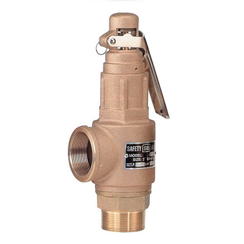
Standard safety valves are generally fitted with an easing lever, which enables the valve to be lifted manually in order to ensure that it is operational at pressures in excess of 75% of set pressure. This is usually done as part of routine safety checks, or during maintenance to prevent seizing. The fitting of a lever is usually a requirement of national standards and insurance companies for steam and hot water applications. For example, the ASME Boiler and Pressure Vessel Code states that pressure relief valves must be fitted with a lever if they are to be used on air, water over 60°C, and steam.
A standard or open lever is the simplest type of lever available. It is typically used on applications where a small amount of leakage of the fluid to the atmosphere is acceptable, such as on steam and air systems, (see Figure 9.2.5 (a)).
Where it is not acceptable for the media to escape, a packed lever must be used. This uses a packed gland seal to ensure that the fluid is contained within the cap, (see Figure 9.2.5 (b)).
For service where a lever is not required, a cap can be used to simply protect the adjustment screw. If used in conjunction with a gasket, it can be used to prevent emissions to the atmosphere, (see Figure 9.2.6).
A test gag (Figure 9.2.7) may be used to prevent the valve from opening at the set pressure during hydraulic testing when commissioning a system. Once tested, the gag screw is removed and replaced with a short blanking plug before the valve is placed in service.
The amount of fluid depends on the particular design of safety valve. If emission of this fluid into the atmosphere is acceptable, the spring housing may be vented to the atmosphere – an open bonnet. This is usually advantageous when the safety valve is used on high temperature fluids or for boiler applications as, otherwise, high temperatures can relax the spring, altering the set pressure of the valve. However, using an open bonnet exposes the valve spring and internals to environmental conditions, which can lead to damage and corrosion of the spring.
When the fluid must be completely contained by the safety valve (and the discharge system), it is necessary to use a closed bonnet, which is not vented to the atmosphere. This type of spring enclosure is almost universally used for small screwed valves and, it is becoming increasingly common on many valve ranges since, particularly on steam, discharge of the fluid could be hazardous to personnel.
Some safety valves, most commonly those used for water applications, incorporate a flexible diaphragm or bellows to isolate the safety valve spring and upper chamber from the process fluid, (see Figure 9.2.9).
An elastomer bellows or diaphragm is commonly used in hot water or heating applications, whereas a stainless steel one would be used on process applications employing hazardous fluids.
The S100 Safety Shut Off valve is mainly used to avoid any damage to components as well as to avoid too high or too low pressure in the gas train. This could cause high financial losses and/or injured ...
130 Series Safety valves are also available as Relief valves. Relief valves, identified by the letter R after the type number, are devices with an operational function, ...
Parker"s cartridge safety relief valves (CSRV) are designed to offer the highest level of protection while maintaining easy serviceability. The CSRV was designed from the existing Parker ...
With DirectIndustry you can: Find the product, subcontractor or service provider you need | Find a nearby distributor or reseller| Contact the manufacturer to get a quote or a price | Examine product characteristics and technical specifications for major brands | View PDF catalogues and other online documentation

Relief and safety Valves are used in high pressure systems to control the pressure and keep balance of the system. The different between safety valves and relief valves is that the safety valves fully open or close under a certain pressure while the relief valves can open in proportion to the pressure in front of them. The safety and pressure relief valves are used automatically. They both operate under similar conditions. When the pressure builds up in a system, it has to be managed by releasing the material to flow through. These valves have a threshold pressure at which they open. The consolidated safety and safety relief valves comprise of a bonnet vent and bellow with springs.
The springs are set up for the threshold pressure and when the pressure exceeds the threshold, the spring is pushed into the bonnet vent and the bellow opens the valve. The Safety Relief Valves can be open and shut valves. They either open or shut off at any given pressure. This is mostly for the safety of an application not to explode under high pressure. The Pressure Relief Valve on the other hand releases the material after the threshold pressure, but not fully. If the pressure is slightly higher the threshold, then the valve opens slightly. If the pressure is very high above the threshold, it opens wider. It also functions in the same manner when the pressure drops down. The valve closes in proportion to the pressure. The safety valve shuts down at once only when the pressure is below the threshold.
Ready Stock of ASTM A351 CF8M Spring Loaded Safety Valve in wide range of Sizes, Stainless Steel Air Compressor Pressure Relief Valve Manufacturers In India
Relief Valves are designed to control pressure in a system While Safety Valves are used for controlling the pressure in a system they release pressure immediately in the event of an emergency or system failure
The Setpoint of relief valve is usually set at 10 Percent above working pressure limit while safety valve is usually set at 3% above working pressure limit.
If you are operating systems that can only be off for short periods of time, it is sensible to keep a spare valve to swap over and then the removed valve can be inspected and recertified.

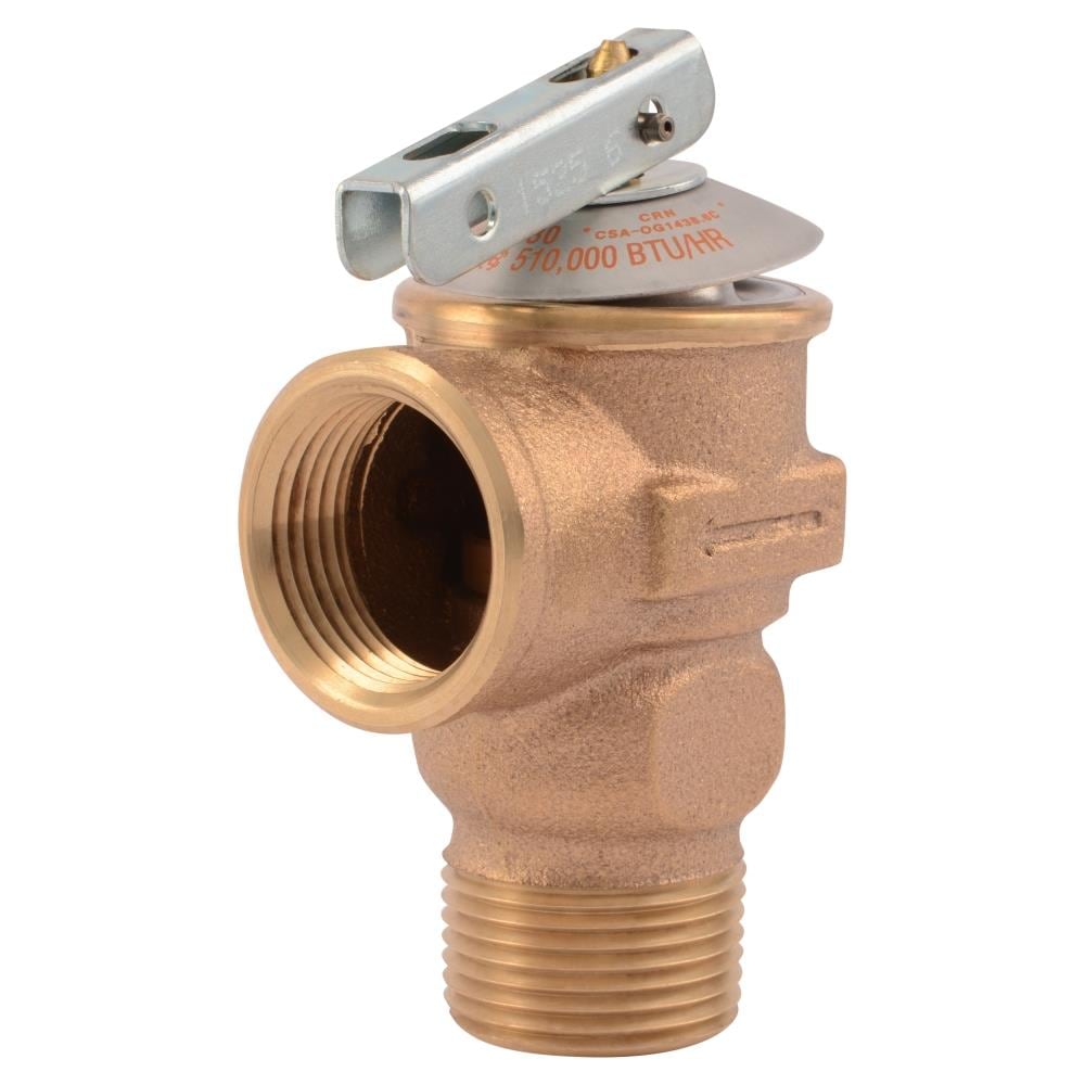
Stainless Steel Safety Relief Valve is a safety mechanism deployed in applications to prevent them from bursting under pressure. Suraj Metal Corporationis a leading manufacturer and supplier of the different types such as the Brass Safety Valveand others in various sizes and dimensions. The valves are fitted with the pipelines in a way that when the pressure goes above the threshold level, the Stainless Steel Air Safety Valveopens up and relieves the system of pressure.
This is important to prevent the pipes from being damaged or bursting under high pressure. The Stainless Steel Safety Exhaust Ball Valveis used in the exhaust systems where the temperature plays major role. When the temperature exceeds certain point, it increases pressure and the safety valve opens and balances the pressure in the system. The spring loaded boiler safety valveis used in boilers and heat exchanger systems where steam and hot water are circulated through pipes. There are different gas safety valvetypes and each of these differ in their purpose and functions. Please feel free to contact us for more information on the different types of air compressor pressure relief valveand others with pricing.
We Keep Bulk Stock of CF8 stainless steel Pressure Safety Valve at our stockyard, contact us for Free Sample & stock list, View Brass Safety Valve Dimension chart
find Stainless Steel Safety Exhaust Ball Valve Dimensions, price list, size chart here, Buy ASTM A351 CF8M 316 temperature safety valve at best price in India

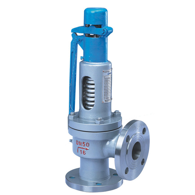
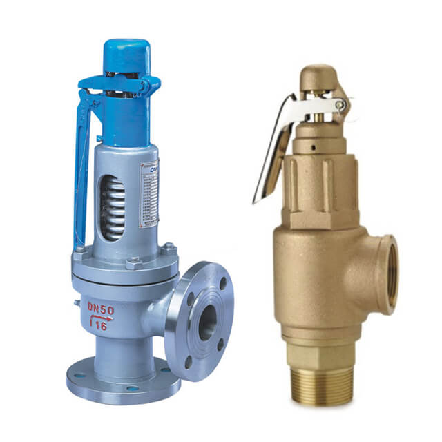
Manufacturer of a wide range of products which include boiler safety valve, safety valve-pop type, pressure safety valve, spring loaded safety valve, safety relief valve and ibr safety valve.
ConnectionThreaded and Flanged EndsWe are the manufacturer, Supplier, and Exporter of Boiler Safety Valve from Chennai -India to Globally. These Safety Valves are Used to release the excess pressure inside the Boiler, High-Pressure Tanks, nd Vessels. So that Pressure can be maintained uniformly. we are manufacturer of valves like: Pressure Relief Valves, Safety relief Valves, Vacuum Relief Valve, Pressure cum vacuum relief valve, Breather valves.
Certificate-ApprovalISO, IBR, IRS, ATEX, TUV, BV, SGSWe are the manufacturer, supplier, and exporter of Safety Valves from Chennai-India to Globally. Used for controlling excess pressures, their precision construction standards make them extensively used in equipment like pressure vessels, pipelines & reactors.We have good infrastructure facility for EXPORT
LeverPlain and Packed LeverBEEKAY brand Safety Valve, Safety Relief Valve, pressure Safety Valves are manufactured by LEVEL AND FLOW CONTROL ENGINEERS in India. Pressure Safety Valve can safeguard the tanks, vessels, boilers, and other capital equipments. when the pressure is esceed the limit valve will open automatically and release the excess pressure.we are expecting enquiry and orders from all over the world.
Accumulation0 to 10%LFCE Spring Loaded Safety Valve, Safety Relief Valves and Pressure Relief Valves are high performance and cost effective. Based on client request we can ready to supply valves with 0 to 5% accumulation and blowdown.Valve size : 1/4" to 12"
Country of OrginIndiaBEEKAY brand Safety Valve, Safety Relief Valve are manufactured by Level and Flow Control Engineers in INDIA. Valves are 100% safe and accuracy for Set pressure and Re-set pressures. Valves are mounted on pipelines, tanks, vessels and reactors to safeguard the capital equipments.We have already exported our range of products to all over the world like UAE, Middle East, Germany, Italay, Australlia, Malysia, Thailand, Indonesia, Philipines, Burunei, Srilanka, Pakistan, Netherland and many more
Flange Ratings150, 300, 600, 900, 1500 lbs RatingsLFCE Manufacturing, supplying, Exporting IBR Certified Safety Valves for Boilers, Deareators, LP, HP Heaters, Condensate Tanks and Vessels. We can able to supply the valves size from 25NB to 300NB and the Pressure Rating 150 lbs to 1500 lbs
We are expecting enquiry and orders from all over the world. Our valves and range of products are well exported to UAE, MIddle East, Thailand, Indonesia, Mayanmar, Vietnam, Srilanka, Malaysia, Singapore, Philipines, Australlia, Netherland, Italy, UAE, South African Countires.
Country of OriginMade in IndiaLFCE manufacturing, supplying, EXPORTING Safety Valve, Pressure Relief Valves with Lever and Plain types.We can able to supply CS, SS, DSS, SDSS, Alloy Steel grade of Materials with Max. of Pressure of 150 barValve size from 15NB to 200NBWe are expecting good enquiry and orders from all over the globe.
Rust ResistanceYesLFCE manufacturing and supplying Beekay brand Brass Safety Valves, Safety Relief Valves, Pressure Relief Valves fo the pressure vessels and Air Receivers. When the pressure is exceed the limit then the valve will open automatically and safeguard the capital equipments.Our brand Beekay is well known in the global market. Already we exported our range of products to all over the world :- UAE, Middle East, South Africa, Zimbawe, Zambia, Kenya, Oman, Saudi Arabia, Thailand, Indonesia, Philipines, Burunei, Srilanka, Pakistan, Hongkong, Netherland, Italay and many more
Flange StandardsANSI, BS, DIN, JS, IS, ASMELFCE manufacturing and EXPORTING Low Pressure, Medium Pressure, High Pressure Safety Valves, Safety Relief Valves for the Process Industries and Hydro Carbon Projects.Our Valves are manufactured and tested as per API StandardsWe are expecting enquiry/orders from all over the world.
Boilers are high pressure and temperature systems used for generating steam to drive steam turbines for electricity generation If due to any reason of operation or malfunction in equipment or controls the operating pressure in the system goes above the safe limit of the material of construction it can cause catastrophe To prevent such catastrophes safety valves are provided in the boiler at various locations
Boiler explosions have been responsible for widespread damage to companies throughout the years, and that’s why today’s boilers are equipped with safety valves and/or relief valves. Boiler safety valves are designed to prevent excess pressure, which is usually responsible for those devastating explosions. That said, to ensure that boiler safety valves are working properly and providing adequate protection, they must meet regulatory specifications and require ongoing maintenance and periodic testing. Without these precautions, malfunctioning safety valves may fail, resulting in potentially disastrous consequences.
Boiler safety valves are activated by upstream pressure. If the pressure exceeds a defined threshold, the valve activates and automatically releases pressure. Typically used for gas or vapor service, boiler safety valves pop fully open once a pressure threshold is reached and remain open until the boiler pressure reaches a pre-defined, safe lower pressure.
Boiler relief valves serve the same purpose – automatically lowering boiler pressure – but they function a bit differently than safety valves. A relief valve doesn’t open fully when pressure exceeds a defined threshold; instead, it opens gradually when the pressure threshold is exceeded and closes gradually until the lower, safe threshold is reached. Boiler relief valves are typically used for liquid service.
There are also devices known as “safety relief valves” which have the characteristics of both types discussed above. Safety relief valves can be used for either liquid or gas or vapor service.
Nameplates must be fastened securely and permanently to the safety valve and remain readable throughout the lifespan of the valve, so durability is key.
The National Board of Boiler and Pressure Vessel Inspectors offers guidance and recommendations on boiler and pressure vessel safety rules and regulations. However, most individual states set forth their own rules and regulations, and while they may be similar across states, it’s important to ensure that your boiler safety valves meet all state and local regulatory requirements.
The National Board published NB-131, Recommended Boiler and Pressure Vessel Safety Legislation, and NB-132, Recommended Administrative Boiler and Pressure Vessel Safety Rules and Regulationsin order to provide guidance and encourage the development of crucial safety laws in jurisdictions that currently have no laws in place for the “proper construction, installation, inspection, operation, maintenance, alterations, and repairs” necessary to protect workers and the public from dangerous boiler and pressure vessel explosions that may occur without these safeguards in place.
The documents are meant to be used as a guide for developing local laws and regulations and also may be used to update a jurisdiction’s existing requirements. As such, they’re intended to be modifiable to meet any jurisdiction’s local conditions.
The American Society of Mechanical Engineers (ASME) governs the code that establishes guidelines and requirements for safety valves. Note that it’s up to plant personnel to familiarize themselves with the requirements and understand which parts of the code apply to specific parts of the plant’s steam systems.
High steam capacity requirements, physical or economic constraints may make the use of a single safety valve impossible. In these cases, using multiple safety valves on the same system is considered an acceptable practice, provided that proper sizing and installation requirements are met – including an appropriately sized vent pipe that accounts for the total steam venting capacity of all valves when open at the same time.
The lowest rating (MAWP or maximum allowable working pressure) should always be used among all safety devices within a system, including boilers, pressure vessels, and equipment piping systems, to determine the safety valve set pressure.
General guidance on proper installation may seem like common sense to experienced installers and inspectors. A few of the most important guidelines and best practices include:
Avoid isolating safety valves from the system, such as by installing intervening shut-off valves located between the steam component or system and the inlet.
Contact the valve supplier immediately for any safety valve with a broken wire seal, as this indicates that the valve is unsafe for use. Safety valves are sealed and certified in order to prevent tampering that can prevent proper function.
Avoid attaching vent discharge piping directly to a safety valve, which may place unnecessary weight and additional stress on the valve, altering the set pressure.
Boiler Valves are integral parts in any steam or heated water applications. safety equipment in steam boilers to control pressure & control temperatures.
When the valve is open the through hole is in line with the fluid flow and it allows the fluid to flow through it. The valve can be closed by rotating the globe by 90 deg. such that the hole now becomes perpendicular to the flow and thus stops the flow.
It’s sheets are usually made up of soft materials to offer tight shutoff. Sometimes sheets can be made from plastic and metals.These valves are not recommended to be used in partial open conditions.
These gates slide down to close the valve. The flow area is equal to the area of the pipe in fully open condition which results in negligible pressure drop across the valve.
These valves are usually used in on/off condition. In partially open conditions due to vibrations the valve is exposed to quick wear and tear.These valves find their use in the petrochemical industry due to the fact that they can work with metal-metal sealing.
These boiler valves consist of a plug which can either be in the shape of a cylinder or conical.The plug also consists of a through slit which remains in-line with the flow in the open condition.
These are the most simple and versatile steam boiler valves. These are also quarter turn operated valves.quarter turn operation ensures quick operating of the valves.in opening condition there is minimum hindrance to the flowing fluid through the valves. This results in very less pressure drop across the valve.
Due to its unique mode of operation, the valve can be actuated easily without requiring wear and tear.its advantage is its compact size which makes its installation process easy.
Globe valve is a linear motion type of valve and is typically used in both on/off conditions.n globe valves, the flow of the fluid through the valve follows an S-path.
Due to this, the flow direction changes twice which results in higher pressure drops. Due to other advantages offered by them, they are widely used in applications where pressure drop through the valve is not a controlling factor.
These are also called as non return valves as they allow the flow to pass through them only in one direction and stop the flow in another direction. Because of this unique property check valves are used in some critical applications in steam systems.
these work simply on the principle of gravity.When the fluid comes in the forward direction, the disc gets lifted from the seat against the gravitational force by the force of incoming fluid. The valve thus allows fluid to pass in this direction. When the fluid comes in the opposite direction, it supports the force of gravity and the disc remains on the seat, keeping the valve closed.
In this kind of check valve, the disc or the closing element swings around a point to which it is hinged. When the fluid comes in the forward direction, the disc swings in an open position allowing the fluid to pass. When the fluid flow comes in the opposite direction, the disc swings and rests on the seat to lose it.
In this kind of check valves, tight shut-off is provided using a spring.the disc on the seat is held back by the spring.even in the forward flow condition, the fluid should exert some pressure, called cracking pressure in order to open the disc against the spring pressure.
This kind of check valve uses diaphragms arranged in such a way that open to allow the flow only in forward direction. When flow comes from the reverse direction, the diaphragms remain closed.

Pressure Relief ValvePioneers in the industry, we offer boiler safety valve, angle safety valve, pilot operated valve, clean steam pressure relief valve, pop safety valve and fire protection pressure relief valve from India.

There is a wide range of safety valves available to meet the many different applications and performance criteria demanded by different industries. Furthermore, national standards define many varying types of safety valve.
The ASME standard I and ASME standard VIII for boiler and pressure vessel applications and the ASME/ANSI PTC 25.3 standard for safety valves and relief valves provide the following definition. These standards set performance characteristics as well as defining the different types of safety valves that are used:
• ASME I valve -A safety relief valve conforming to the requirements of Section I of the ASME pressure vessel code for boiler applications which will open within 3% overpressure and close within 4%. It will usually feature two blowdown rings, and is identified by a National Board ‘V’ stamp.
• ASME VIII valve -A safety relief valve conforming to the requirements of Section VIII of the ASME pressure vessel code for pressure vessel applications which will open within 10% overpressure and close within 7%. Identified by a National Board ‘UV’ stamp.
• Full bore safety valve - A safety valve having no protrusions in the bore, and wherein the valve lifts to an extent sufficient for the minimum area at any section, at or below the seat, to become the controlling orifice.
• Conventional safety relief valve -The spring housing is vented to the discharge side, hence operational characteristics are directly affected by changes in the backpressure to the valve.
• Balanced safety relief valve -A balanced valve incorporates a means of minimising the effect of backpressure on the operational characteristics of the valve.
• Pilot operated pressure relief valve -The major relieving device is combined with, and is controlled by, a self-actuated auxiliary pressure relief device.
• Power-actuated safety relief valve -A pressure relief valve in which the major pressure relieving device is combined with, and controlled by, a device requiring an external source of energy.
• Standard safety valve - A valve which, following opening, reaches the degree of lift necessary for the mass flowrate to be discharged within a pressure rise of not more than 10%. (The valve is characterised by a pop type action and is sometimes known as high lift).
• Full lift (Vollhub) safety valve - A safety valve which, after commencement of lift, opens rapidly within a 5% pressure rise up to the full lift as limited by the design. The amount of lift up to the rapid opening (proportional range) shall not be more than 20%.
• Direct loaded safety valve - A safety valve in which the opening force underneath the valve disc is opposed by a closing force such as a spring or a weight.
• Proportional safety valve -A safety valve which opens more or less steadily in relation to the increase in pressure. Sudden opening within a 10% lift range will not occur without pressure increase. Following opening within a pressure of not more than 10%, these safety valves achieve the lift necessary for the mass flow to be discharged.
• Diaphragm safety valve - A direct loaded safety valve wherein linear moving and rotating elements and springs are protected against the effects of the fluid by a diaphragm.
• Bellows safety valve - A direct loaded safety valve wherein sliding and (partially or fully) rotating elements and springs are protected against the effects of the fluids by a bellows. The bellows may be of such a design that it compensates for influences of backpressure.
• Controlled safety valve -Consists of a main valve and a control device. It also includes direct acting safety valves with supplementary loading in which, until the set pressure is reached, an additional force increases the closing force.
• Safety valve -A safety valve which automatically, without the assistance of any energy other than that of the fluid concerned, discharges a quantity of the fluid so as to prevent a predetermined safe pressure being exceeded, and which is designed to re-close and prevent further flow of fluid after normal pressure conditions of service have been restored. Note; the valve can be characterised either by pop action (rapid opening) or by opening in proportion (not necessarily linear) to the increase in pressure over the set pressure.
• Direct loaded safety valve - A safety valve in which the loading due to the fluid pressure underneath the valve disc is opposed only by a direct mechanical loading device such as a weight, lever and weight, or a spring.
• Assisted safety valve -A safety valve which by means of a powered assistance mechanism, may additionally be lifted at a pressure lower than the set pressure and will, even in the event of a failure of the assistance mechanism, comply with all the requirements for safety valves given in the standard.
• Supplementary loaded safety valve -A safety valve that has, until the pressure at the inlet to the safety valve reaches the set pressure, an additional force, which increases the sealing force.
Note; this additional force (supplementary load), which may be provided by means of an extraneous power source, is reliably released when the pressure at the inlet of the safety valve reaches the set pressure. The amount of supplementary loading is so arranged that if such supplementary loading is not released, the safety valve will attain its certified discharge capacity at a pressure not greater than 1.1 times the maximum allowable pressure of the equipment to be protected.
• Pilot operated safety valve -A safety valve, the operation of which is initiated and controlled by the fluid discharged from a pilot valve, which is itself, a direct loaded safety valve subject to the requirement of the standard.
The terms full lift, high lift and low lift refer to the amount of travel the disc undergoes as it moves from its closed position to the position required to produce the certified discharge capacity, and how this affects the discharge capacity of the valve.
A full lift safety valve is one in which the disc lifts sufficiently, so that the curtain area no longer influences the discharge area. The discharge area, and therefore the capacity of the valve are subsequently determined by the bore area. This occurs when the disc lifts a distance of at least a quarter of the bore diameter. A full lift conventional safety valve is often the best choice for general steam applications.
The disc of a high lift safety valve lifts a distance of at least 1/12th of the bore diameter. This means that the curtain area, and ultimately the position of the disc, determines the discharge area. The discharge capacities of high lift valves tend to be significantly lower than those of full lift valves, and for a given discharge capacity, it is usually possible to select a full lift valve that has a nominal size several times smaller than a corresponding high lift valve, which usually incurs cost advantages.Furthermore, high lift valves tend to be used on compressible fluids where their action is more proportional.
In low lift valves, the disc only lifts a distance of 1/24th of the bore diameter. The discharge area is determined entirely by the position of the disc, and since the disc only lifts a small amount, the capacities tend to be much lower than those of full or high lift valves.
Except when safety valves are discharging, the only parts that are wetted by the process fluid are the inlet tract (nozzle) and the disc. Since safety valves operate infrequently under normal conditions, all other components can be manufactured from standard materials for most applications. There are however several exceptions, in which case, special materials have to be used, these include:
• Cast steel -Commonly used on higher pressure valves (up to 40 bar g). Process type valves are usually made from a cast steel body with an austenitic full nozzle type construction.
For all safety valves, it is important that moving parts, particularly the spindle and guides are made from materials that will not easily degrade or corrode. As seats and discs are constantly in contact with the process fluid, they must be able to resist the effects of erosion and corrosion.
For process applications, austenitic stainless steel is commonly used for seats and discs; sometimes they are ‘stellite faced’ for increased durability. For extremely corrosive fluids, nozzles, discs and seats are made from special alloys such as ‘monel’ or ‘hastelloy’.
The spring is a critical element of the safety valve and must provide reliable performance within the required parameters. Standard safety valves will typically use carbon steel for moderate temperatures. Tungsten steel is used for higher temperature, non-corrosive applications, and stainless steel is used for corrosive or clean steam duty. For sour gas and high temperature applications, often special materials such as monel, hastelloy and ‘inconel’ are used.

The primary purpose of a safety valve is to protect life, property and the environment. Safety valves are designed to open and release excess pressure from vessels or equipment and then close again.
The function of safety valves differs depending on the load or main type of the valve. The main types of safety valves are spring-loaded, weight-loaded and controlled safety valves.
Regardless of the type or load, safety valves are set to a specific set pressure at which the medium is discharged in a controlled manner, thus preventing overpressure of the equipment. In dependence of several parameters such as the contained medium, the set pressure is individual for each safety application.
Fluidyne BoilerFull Lift Full Flow Safety Relief Valve is a high performance valve designed and developed for steam and water service. It can also be used for most other applications like gases and vapors, saturated steam, superheated steam. Fluidyne Safety Relief Valve is designed for steam service. The valves are designed as per API 520, API 526 and meets the requirements of ASME Sec VIII-Division I. Fluidyne Boiler Safety Valves are offered with IBR Certification in Form III-C. The valves have a full nozzle or half nozzle and guided at the guide of the valve body, increasing the eficiency of the valve assembly. Specially designed disc holder ensures full lift within 5% to 10% overpressure or increase of pressure above the set pressure value. Blow down of a maximum of 5% to 10% is achieved in this design. Lapping of valve seat to optical flatness ensures leak tightness at seat. Full lift of valve disc ensures that the certified flow of the safety valve is discharged. Spring made of chrome vanadium steel is precisely selected and assembled so that the valve operates precisely and a good leak tightness is achieved at high temperatures with great repeatability.

It is found on the majority of espresso machine boilers, but there are exceptions, such as Pavoni, Rancilio and few others. As it is a non-returnable item, please measure yours before ordering.

Throughout the years, HZVALVE has developed its Quality System which is an integral part of our manufacturing policy. Our primary goal is to provide products that meet and exceed market standards. In this sense, HZVALVE is an ISO-9001 Audited and Certified Company that has achieved major certifications worldwide. Our system consists of a rigorous quality control as well as the selection of raw materials from approved vendors. Control over our manufacturing process is vital. Serial numbers allow HZVALVE to monitor and trace fabrication processes along with the materials of components.
HZVALVE owned independent quality department with over 25 experienced inspectors. Our target is to cover all vital point including material, procession, assembling, testing and package for overall quality controlling and supervision. We keep the understanding that the high quality products create more value to customers.

Fired pressure vessels shall be fitted with safety relieving devices with sufficient capacity to relieve all vapor that may be generated in the vessels during normal operation. The safety relieving devices shall be fitted with proper controls to ensure safe operation.
To eliminate the necessity of shutting the system down for the inspection, a three-way stop valve may be installed under 2 safety valves, each with the required relieving capacity, installed so that both safety valves cannot be closed off from the vaporizer at the same time. Alternatively may 2 or more separate safety valves be installed with individual shutoff valves, in which case the shutoff valve stems is mechanically interconnected in a manner that allow full required flow capacity at all times.

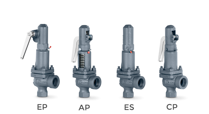
Setpoint Integrated Solutions offers many Safety Valves to meet your specific application needs. Highlighted below is our wide array of Consolidated Products
The Consolidated Type 1700 Maxiflow High Pressure Safety Valve is a premium product that is installed on a majority of power generating stations worldwide to protect boilers from over-pressure conditions.
The Consolidated Type 1511 Steam Safety Valve are designed for low-pressure steam heating boilers and steam generators as well as air service applications
This website is using a security service to protect itself from online attacks. The action you just performed triggered the security solution. There are several actions that could trigger this block including submitting a certain word or phrase, a SQL command or malformed data.


 8613371530291