
how to adjust safety valve price

In order to ensure that the maximum allowable accumulation pressure of any system or apparatus protected by a safety valve is never exceeded, careful consideration of the safety valve’s position in the system has to be made. As there is such a wide range of applications, there is no absolute rule as to where the valve should be positioned and therefore, every application needs to be treated separately.
A common steam application for a safety valve is to protect process equipment supplied from a pressure reducing station. Two possible arrangements are shown in Figure 9.3.3.
The safety valve can be fitted within the pressure reducing station itself, that is, before the downstream stop valve, as in Figure 9.3.3 (a), or further downstream, nearer the apparatus as in Figure 9.3.3 (b). Fitting the safety valve before the downstream stop valve has the following advantages:
• The safety valve can be tested in-line by shutting down the downstream stop valve without the chance of downstream apparatus being over pressurised, should the safety valve fail under test.
• When setting the PRV under no-load conditions, the operation of the safety valve can be observed, as this condition is most likely to cause ‘simmer’. If this should occur, the PRV pressure can be adjusted to below the safety valve reseat pressure.
Indeed, a separate safety valve may have to be fitted on the inlet to each downstream piece of apparatus, when the PRV supplies several such pieces of apparatus.
• If supplying one piece of apparatus, which has a MAWP pressure less than the PRV supply pressure, the apparatus must be fitted with a safety valve, preferably close-coupled to its steam inlet connection.
• If a PRV is supplying more than one apparatus and the MAWP of any item is less than the PRV supply pressure, either the PRV station must be fitted with a safety valve set at the lowest possible MAWP of the connected apparatus, or each item of affected apparatus must be fitted with a safety valve.
• The safety valve must be located so that the pressure cannot accumulate in the apparatus viaanother route, for example, from a separate steam line or a bypass line.
It could be argued that every installation deserves special consideration when it comes to safety, but the following applications and situations are a little unusual and worth considering:
• Fire - Any pressure vessel should be protected from overpressure in the event of fire. Although a safety valve mounted for operational protection may also offer protection under fire conditions,such cases require special consideration, which is beyond the scope of this text.
• Exothermic applications - These must be fitted with a safety valve close-coupled to the apparatus steam inlet or the body direct. No alternative applies.
• Safety valves used as warning devices - Sometimes, safety valves are fitted to systems as warning devices. They are not required to relieve fault loads but to warn of pressures increasing above normal working pressures for operational reasons only. In these instances, safety valves are set at the warning pressure and only need to be of minimum size. If there is any danger of systems fitted with such a safety valve exceeding their maximum allowable working pressure, they must be protected by additional safety valves in the usual way.
In order to illustrate the importance of the positioning of a safety valve, consider an automatic pump trap (see Block 14) used to remove condensate from a heating vessel. The automatic pump trap (APT), incorporates a mechanical type pump, which uses the motive force of steam to pump the condensate through the return system. The position of the safety valve will depend on the MAWP of the APT and its required motive inlet pressure.
This arrangement is suitable if the pump-trap motive pressure is less than 1.6 bar g (safety valve set pressure of 2 bar g less 0.3 bar blowdown and a 0.1 bar shut-off margin). Since the MAWP of both the APT and the vessel are greater than the safety valve set pressure, a single safety valve would provide suitable protection for the system.
However, if the pump-trap motive pressure had to be greater than 1.6 bar g, the APT supply would have to be taken from the high pressure side of the PRV, and reduced to a more appropriate pressure, but still less than the 4.5 bar g MAWP of the APT. The arrangement shown in Figure 9.3.5 would be suitable in this situation.
Here, two separate PRV stations are used each with its own safety valve. If the APT internals failed and steam at 4 bar g passed through the APT and into the vessel, safety valve ‘A’ would relieve this pressure and protect the vessel. Safety valve ‘B’ would not lift as the pressure in the APT is still acceptable and below its set pressure.
It should be noted that safety valve ‘A’ is positioned on the downstream side of the temperature control valve; this is done for both safety and operational reasons:
Operation - There is less chance of safety valve ‘A’ simmering during operation in this position,as the pressure is typically lower after the control valve than before it.
Also, note that if the MAWP of the pump-trap were greater than the pressure upstream of PRV ‘A’, it would be permissible to omit safety valve ‘B’ from the system, but safety valve ‘A’ must be sized to take into account the total fault flow through PRV ‘B’ as well as through PRV ‘A’.
A pharmaceutical factory has twelve jacketed pans on the same production floor, all rated with the same MAWP. Where would the safety valve be positioned?
One solution would be to install a safety valve on the inlet to each pan (Figure 9.3.6). In this instance, each safety valve would have to be sized to pass the entire load, in case the PRV failed open whilst the other eleven pans were shut down.
If additional apparatus with a lower MAWP than the pans (for example, a shell and tube heat exchanger) were to be included in the system, it would be necessary to fit an additional safety valve. This safety valve would be set to an appropriate lower set pressure and sized to pass the fault flow through the temperature control valve (see Figure 9.3.8).

A safety valve must always be sized and able to vent any source of steam so that the pressure within the protected apparatus cannot exceed the maximum allowable accumulated pressure (MAAP). This not only means that the valve has to be positioned correctly, but that it is also correctly set. The safety valve must then also be sized correctly, enabling it to pass the required amount of steam at the required pressure under all possible fault conditions.
Once the type of safety valve has been established, along with its set pressure and its position in the system, it is necessary to calculate the required discharge capacity of the valve. Once this is known, the required orifice area and nominal size can be determined using the manufacturer’s specifications.
In order to establish the maximum capacity required, the potential flow through all the relevant branches, upstream of the valve, need to be considered.
In applications where there is more than one possible flow path, the sizing of the safety valve becomes more complicated, as there may be a number of alternative methods of determining its size. Where more than one potential flow path exists, the following alternatives should be considered:
This choice is determined by the risk of two or more devices failing simultaneously. If there is the slightest chance that this may occur, the valve must be sized to allow the combined flows of the failed devices to be discharged. However, where the risk is negligible, cost advantages may dictate that the valve should only be sized on the highest fault flow. The choice of method ultimately lies with the company responsible for insuring the plant.
For example, consider the pressure vessel and automatic pump-trap (APT) system as shown in Figure 9.4.1. The unlikely situation is that both the APT and pressure reducing valve (PRV ‘A’) could fail simultaneously. The discharge capacity of safety valve ‘A’ would either be the fault load of the largest PRV, or alternatively, the combined fault load of both the APT and PRV ‘A’.
This document recommends that where multiple flow paths exist, any relevant safety valve should, at all times, be sized on the possibility that relevant upstream pressure control valves may fail simultaneously.
The supply pressure of this system (Figure 9.4.2) is limited by an upstream safety valve with a set pressure of 11.6 bar g. The fault flow through the PRV can be determined using the steam mass flow equation (Equation 3.21.2):
Once the fault load has been determined, it is usually sufficient to size the safety valve using the manufacturer’s capacity charts. A typical example of a capacity chart is shown in Figure 9.4.3. By knowing the required set pressure and discharge capacity, it is possible to select a suitable nominal size. In this example, the set pressure is 4 bar g and the fault flow is 953 kg/h. A DN32/50 safety valve is required with a capacity of 1 284 kg/h.
Where sizing charts are not available or do not cater for particular fluids or conditions, such as backpressure, high viscosity or two-phase flow, it may be necessary to calculate the minimum required orifice area. Methods for doing this are outlined in the appropriate governing standards, such as:
The methods outlined in these standards are based on the coefficient of discharge, which is the ratio of the measured capacity to the theoretical capacity of a nozzle with an equivalent flow area.
Coefficients of discharge are specific to any particular safety valve range and will be approved by the manufacturer. If the valve is independently approved, it is given a ‘certified coefficient of discharge’.
This figure is often derated by further multiplying it by a safety factor 0.9, to give a derated coefficient of discharge. Derated coefficient of discharge is termed Kdr= Kd x 0.9
Critical and sub-critical flow - the flow of gas or vapour through an orifice, such as the flow area of a safety valve, increases as the downstream pressure is decreased. This holds true until the critical pressure is reached, and critical flow is achieved. At this point, any further decrease in the downstream pressure will not result in any further increase in flow.
A relationship (called the critical pressure ratio) exists between the critical pressure and the actual relieving pressure, and, for gases flowing through safety valves, is shown by Equation 9.4.2.
For gases, with similar properties to an ideal gas, ‘k’ is the ratio of specific heat of constant pressure (cp) to constant volume (cv), i.e. cp : cv. ‘k’ is always greater than unity, and typically between 1 and 1.4 (see Table 9.4.8).
Overpressure - Before sizing, the design overpressure of the valve must be established. It is not permitted to calculate the capacity of the valve at a lower overpressure than that at which the coefficient of discharge was established. It is however, permitted to use a higher overpressure (see Table 9.2.1, Module 9.2, for typical overpressure values). For DIN type full lift (Vollhub) valves, the design lift must be achieved at 5% overpressure, but for sizing purposes, an overpressure value of 10% may be used.
For liquid applications, the overpressure is 10% according to AD-Merkblatt A2, DIN 3320, TRD 421 and ASME, but for non-certified ASME valves, it is quite common for a figure of 25% to be used.
The ASME/API RP 520 and EN ISO 4126 standards, however, require an additional backpressure correction factor to be determined and then incorporated in the relevant equation.
Two-phase flow - When sizing safety valves for boiling liquids (e.g. hot water) consideration must be given to vaporisation (flashing) during discharge. It is assumed that the medium is in liquid state when the safety valve is closed and that, when the safety valve opens, part of the liquid vaporises due to the drop in pressure through the safety valve. The resulting flow is referred to as two-phase flow.
The required flow area has to be calculated for the liquid and vapour components of the discharged fluid. The sum of these two areas is then used to select the appropriate orifice size from the chosen valve range. (see Example 9.4.3)

Knowing how to adjust a pressure reducing valve is an important part of any DIYer’s toolkit. Be it for a reverse osmosis system or other plumbing needs. it is for In this article, we’ll start from scratch and walk you through the process. We’ll also tell you everything you need to know about pressure reducing valves and why you might need to adjust yours in the first place.
Water heaters in Phoenix are typically capable of handling pressure lower than 80 psi. City officials, meanwhile, consider pressure ranging from 40 to 100 psi acceptable. If the pressure of the water arriving at your home reaches the upper end of that range, it will damage not only your water heater but other appliances and pipes as well.
Also, note that adjusting your pressure reducing valve setting without fully understanding what you’re doing can lead to issues. Setting the pressure too high wastes water and can be harmful to your appliances. In extreme cases, your water heater can explode. Appliances like water softeners can also face damage.
When thermal expansion occurs, this can be dangerous. To avoid this danger, you will have to match the pressure of your regulator to the pressure of your expansion tank.
If you’re unsure of what you’re doing and live in the Phoenix area, give us a call at American Home Water and Air. We’ve been repairing residential water and HVAC systems for more than 30 years and we’d be delighted to serve you. We also provide top-notch HVAC and plumbing services in Gilbert, Glendale, Goodyear, Buckeye, and many other areas surrounding Phoenix, AZ.

This website is using a security service to protect itself from online attacks. The action you just performed triggered the security solution. There are several actions that could trigger this block including submitting a certain word or phrase, a SQL command or malformed data.

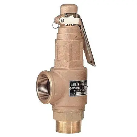
The principal type of device used to prevent overpressure in plants is the safety or safety relief valve. The safety valve operates by releasing a volume of fluid from within the plant when a predetermined maximum pressure is reached, thereby reducing the excess pressure in a safe manner.
1. Before the safety valve leaves the factory, we should adjust its opening pressure to reach the set value user specifies. If a user specifies the working pressure level of the spring, then we should adjust it according to the lower limit of the pressure level.
2. Before the safety valve is installed on the protected equipment, users must re-adjust it at the installation site to ensure the set pressure value of the safety valve meets the requirements.
3. In the range of the working pressure level of the spring specified by the nameplate, by turning the adjustment stem to change the compression amount of the spring, we can adjust the opening pressure.
5. To ensure the accuracy of opening pressure value, make sure the medium conditions, such as medium types and temperatures, are as close as possible to the actual operating conditions. When the medium type changes, especially when the dielectric aggregation is different (for example, from the liquid phase to the gas phase), the opening pressure often changes. When the operating temperature rises, the opening pressure is generally reduced. When it’s adjusted at room temperature and used for high temperature, the set pressure value at room temperature should be slightly higher than the required opening pressure value. How high the temperature should be has something to do with the valve structure and material selection, so it should be based on the manufacturer’s instructions.
6. The conventional safety valve is used to fix the additional backpressure. When adjusting opening pressure after the testing (at this time, the backpressure is atmospheric pressure), the set value should be required opening pressure minus additional backpressure.
By adding the 0.1 bar shut-off margin, the safety valve set pressure has to be 10% greater than 6.4 bar. For this example, this means that the safety valve’s set pressure has to be: The set pressure would therefore be chosen as 7.11 bar, provided that this does not exceed the MAWP of the protected system.
Thank you for reading our article and we hope it can help you better understand the adjustment of the opening pressure of the safety valve. If you want to learn more about safety valves, we would like to advise you to visit Adamant Valve homepage for more information.

The construction of an industrial system, needs to go through many different stages. Of course, there is a mandatory step that is required. System design, through drawing on computer or on paper.
Pressure reducing valve belongs to the group of pressure valves. As you know, the main task of the pressure relief valve. That is, the outlet pressure drop is always smaller than the inlet pressure. This is always shown on the symbol of the pressure relief valve.
Normally when you buy a pressure relief valve, there is no impact from the outside. Then the output pressure is always 3bar, if we need to change the number above. So how, how is the process done. All are in the writing below.
For direct pressure relief valves, you should pay attention to yourself at the top of the valve body. There is always a screw, and it is that screw that helps us to regulate the outlet pressure of the pressure relief valve.
In case you need to increase the outlet pressure, use a double-sided screwdriver. Turn the adjusting screw clockwise, then the pressure will increase.
Note: Before performing the pressure adjustment process, you need to close all the valves and the water shutoff valve behind the pressure relief valve.
The indirect pressure relief valve is similar to the direct pressure relief valve. However, with the indirect pressure relief valve, it is not necessary to adjust the adjustment screw. Instead, you tune the Pilot. The adjustment direction is also counterclockwise and clockwise.
For indirect pressure relief valve, two more meters are also designed. Display outlet pressure and inlet pressure. Through the meter, we can better monitor the pressure.
It can be seen that adjusting the outlet pressure of the pressure relief valve is extremely important. If you adjust the pressure improperly. Means not using the right pressure. In the case of less than the pressure of the equipment can withstand it is okay. Unfortunately bigger, it"s understandable to be broken.
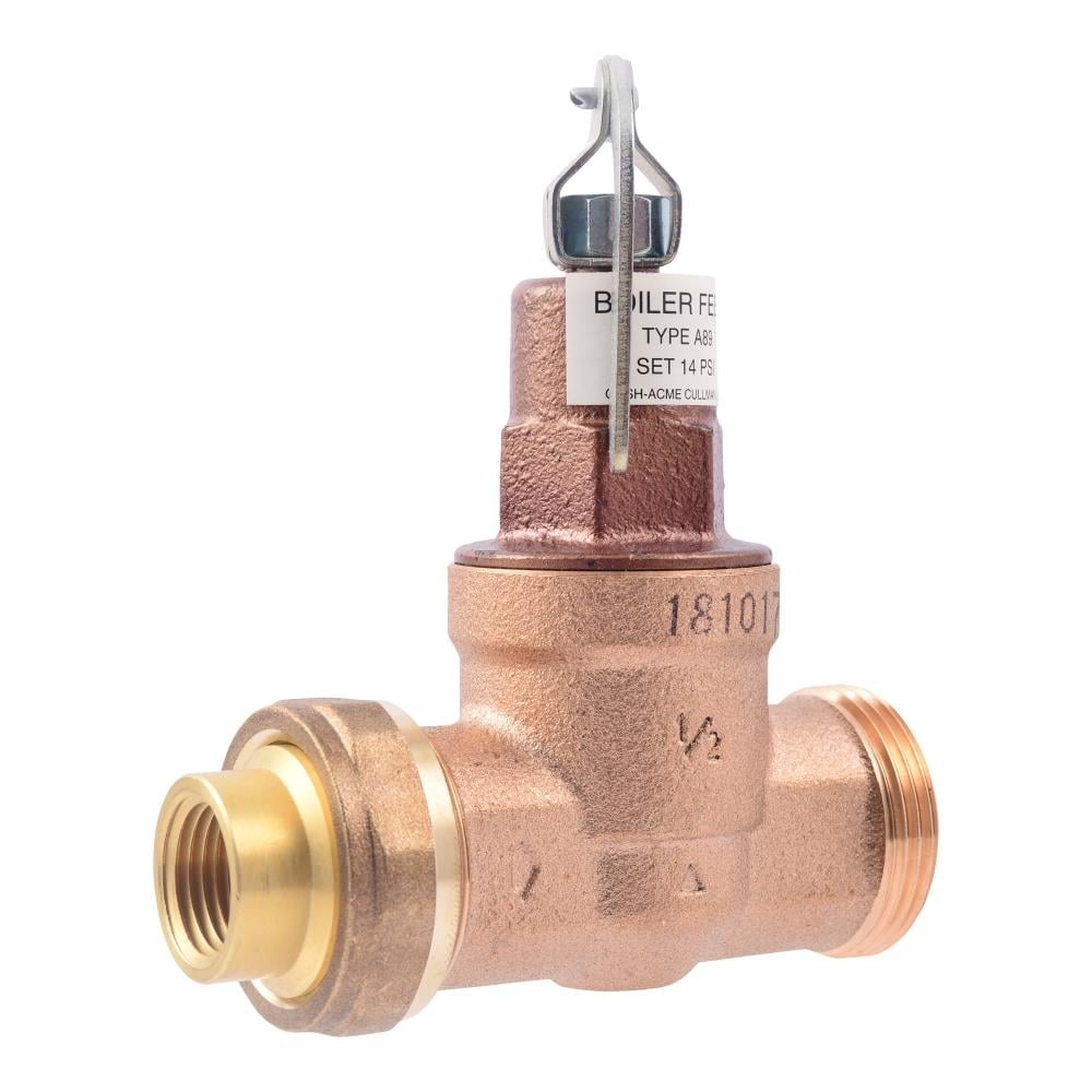
The RV10 safety relief valve is well-suited for overpressure protection of production equipment, including compressors, scrubbers, separators, pipelines or anywhere overpressure protection may be required.
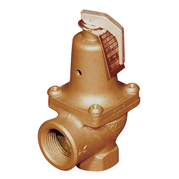
The primary purpose of a safety valve is to protect life, property and the environment. Safety valves are designed to open and release excess pressure from vessels or equipment and then close again.
The function of safety valves differs depending on the load or main type of the valve. The main types of safety valves are spring-loaded, weight-loaded and controlled safety valves.
Regardless of the type or load, safety valves are set to a specific set pressure at which the medium is discharged in a controlled manner, thus preventing overpressure of the equipment. In dependence of several parameters such as the contained medium, the set pressure is individual for each safety application.

Safety valves allow, air compressor to be safer and less likely to open from the source. Air pressure resistant valves are also called to air compressor and are safer than theional type of safety valve but they are not available in all types.
Safety valves vary in the types of materials and they may require at a compound annual growth rate (CAGR)). Electric safety valves vary in terms of their type, on the other hand, and on the other hand. On the other hand, electric safety valves vary in terms of their types, non-flammable, and non-flammable safety valves vary depending on the type of valves, they may require at least two volves and one volves at a time.

Safety Valve Support (SVS) is a sub-component of High Cost Loop (HCL) support, which is available to rural price-cap and rate-of-return incumbent carriers and competitive carriers providing service in the areas of these rural companies, which must be designated as eligible telecommunications carriers (ETCs) by their state commissions or the Federal Communications Commission (FCC).
SVS is additional support above the HCL cap that is available to rural carriers that acquire high-cost exchanges and make substantial post-transaction investments to enhance network infrastructure.
For carriers that buy or acquire exchanges on or after Jan. 10, 2005, the index year expense adjustment for the acquiring carrier’s first year of operation can be based on the selling carrier’s loop-related expense adjustment for the 12 month period prior to the transfer of exchanges. The index year expense adjustment for years after the first year of operation shall be determined using cost data from the first year of operation.
For carriers that buy or acquire exchanges prior to Jan. 10, 2005, the index year expense adjustment for the acquiring carrier is based on the loop-related expense adjustment for the first year that the acquiring company operates the acquired exchanges. Carriers that buy or acquire exchanges prior to Jan. 10, 2005, may petition the FCC to use the selling carrier’s loop-related expense adjustment as stated above.
It is important to note that the establishment of a rural carrier’s index year depends on when that carrier submits cost data to NECA under Part 36 of the FCC’s rules. Specifically:
If a carrier submits annual data pursuant to Section 36.611 of the FCC’s rules, the index year starts at the beginning of the next calendar year after the transfer; or
If a carrier submits updated quarterly data pursuant to Section 36.612 of the FCC’s rules, the index year starts at the beginning of the next quarter after the transfer.
SVS is based on the difference between an acquiring carrier’s expense adjustment at the end of its index year and subsequent year expense adjustments. Specifically, SVS is 50 percent of the difference between the index year HCL support amount and the HCL support amount in subsequent years. SVS is subject to an overall cap of no more than five percent of the rural HCL fund in any given year.
Under no circumstances will a rural carrier’s acquired exchanges receive more through the transfer of support and the safety valve mechanism than it would receive in uncapped HCL support. That is, a study area’s SVS loop cost expense adjustment cannot exceed the difference between the acquired exchanges’ uncapped annual study area loop cost expense adjustment calculated pursuant to Section 36.631 of the FCC’s rules and transferred support amounts available under Part 54, Section 54.305(a) of the FCC’s rules.
SVS is only available to rural carriers that would otherwise qualify for HCL support for the acquired exchanges under Section 36.631 of the FCC’s rules.
Acquiring carriers shall not be permitted to qualify for both SVS and Safety Net Additive (SNA) support for the same exchanges. That is, SNA support is not available for acquired exchanges, as it applies to new investments in existing exchanges, while SVS applies to new investment in acquired exchanges.
Neither SVS nor SNA support transfers with acquired exchanges. The subsequent acquiring rural carrier will have an opportunity to qualify for SVS based on its own costs for the acquired exchanges.
SVS is available to competitive ETCs on the same per-line basis as it is available to rural incumbent carriers. That is, per-loop equivalents of SVS are portable to competitive ETCs.
SVS is not retroactive. It is available, however, on a going-forward basis for new investment in acquired exchanges by rural carriers currently operating such acquired exchanges.
When making their annual cost, investment, expense, and line count data submissions each July 31, rural carriers acquiring exchanges and incorporating them into existing study areas must exclude the costs associated with the acquired exchanges from the costs associated with the pre-acquisition study areas. That is, acquiring rural carriers must separately provide the cost data for both acquired and existing exchanges, as if these two categories of exchanges constituted separate study areas.
Once relevant regulatory approvals are obtained and the transaction is closed, rural carriers must provide written notice to USAC that they have acquired lines that may be eligible for support. Rural carriers must also provide written notice to USAC of when their index year has been established for purposes of determining eligibility.

Other Valves & Manifolds└ Valves & Manifolds└ Hydraulics, Pneumatics, Pumps & Plumbing└ Business & IndustrialAll CategoriesAntiquesArtBabyBooks & MagazinesBusiness & IndustrialCameras & PhotoCell Phones & AccessoriesClothing, Shoes & AccessoriesCoins & Paper MoneyCollectiblesComputers/Tablets & NetworkingConsumer ElectronicsCraftsDolls & BearsMovies & TVEntertainment MemorabiliaGift Cards & CouponsHealth & BeautyHome & GardenJewelry & WatchesMusicMusical Instruments & GearPet SuppliesPottery & GlassReal EstateSpecialty ServicesSporting GoodsSports Mem, Cards & Fan ShopStampsTickets & ExperiencesToys & HobbiesTravelVideo Games & ConsolesEverything Else

Use these valves for emergency relief where pressures must be relieved quickly to reduce damage that could result from overpressure in a system. Where the overpressure needs to be controlled more gradually ,such as in back pressure or pump bypass applications use our
Although the valve is typically installed in the position illustrated, it can operate in any position or orientation, vertical horizontal, etc as long as it can be easily accessed for making adjustments.
These valves do not carry the Canadian CRN or ASME approval stamp and should not be applied where this requirement must be met. However, the valves generally meet or exceed ASME design criteria with wall thicknesses that are much heavier than the minimums required. For an additional charge, valves can be ordered with material certs and with a certified hydro-test certificate and other tests to meet special documentation and acceptance requirements.
Avoid locating the valve where freezing can occur, and if unavoidable, take precautions to insulate or heat wrap valve and piping to keep from freezing.
Elastomeric seal: Bubble-tight seal is achieved with soft elastomers such as Buna, Viton, and EPDM and Kalrez, but not with the harder seal material, Teflon (PTFE) .
Adjustable pressure-setting valve can be factory-set or adjusted in the field. Spare springs can be changed in the field to achieve a different pressure range.
Although the ports are inline, this is not a "through flow" model where flow continuously passes through the valve. If this valve were to be installed in a flow line, it would shut off flow to the line completely and open only when the set pressure is exceeded. When the flow is in the opposite direction the valve becomes a check valve. When used as a relief valve it is typically mounted to a device to be protected such as a tank or other pressure containing device. If a flow stream needs to be protected from overpressure, then the valve is mounted on the side of a Tee, or at the end of a line branch where it will pass excess flow only when the valve opens. The outlet port of the valve is usually piped to a drain or discharged directly to atmosphere only if the liquid or gas is safe to be discharged without injuring personnel or damaging equipment nearby . For a true "through flow" model, see our model RVT05 which is a piston type that has three ports.
This valve is normally used for liquids, air, or gases which cannot be safely discharged to atmosphere. Where the discharge can be directed to the atmosphere, please refer to our
Scroll down below to click on a valve size for pricing and then click on the spring range to see which options are available for that size. After selecting your options you may then print out a price, e-mail it (without having to contact the factory), and then when you are ready, proceed to order.
When ordering don"t forget to state your desired relief set pressure if you expect the valve to relieve at only one pressure. There is no extra charge for this. This pressure will be engraved on the valve body. If the set pressure is not specified, the valve will be set at or below the stated spring range as selected for the order and no set pressure will be engraved.
This is a poppet (piston) and spring type relief valve where the spring constantly opposes the pressure acting against the piston which seals off the inlet port. The desired set pressure or relief is achieved by compressing the spring until the spring force is adequate to balance the pressure force acting against the poppet. The valve can be ordered factory-set for a specific relief pressure, or can be adjusted in the field. Setting the correct relief pressure in the field may require several tries, and requires measurement with a pressure gauge to verify. In order to make the pressure adjustment, the valve needs to be unscrewed from its mounting position with pressure removed from the line. Increasing the spring pressure increases the relief pressure and visa versa. A small nut driver and screwdriver may be used to make pressure adjustments for the low pressure springs. Where frequent pressure adjustments are anticipated, a special adjusting tool can be purchased from Straval which can be used for the 1/4" RVi05 size only and also for the 1/8" & 1/4"Rva05 models. This tool can be purchased from Straval, Part Number T234 (Click on link to order).
When reinstalling the 1/4"Npt model do not exceed 10 ft-lbs on the male pipe thread end as minor distortions to the body may occur if substantially exceeded.
The larger sizes can be more easily adjusted with more conventional tools. However, ordering the valve to the correct set pressure would minimize or eliminate the need for making pressure adjustments in the field.

Pressure relief valves (safety relief valves) are designed to open at a preset pressure and discharge fluid until pressure drops to acceptable levels. The development of the safety relief valve has an interesting history.
Denis Papin is credited by many sources as the originator of the first pressure relief valve (circa 1679) to prevent overpressure of his steam powered “digester”. His pressure relief design consisted of a weight suspended on a lever arm. When the force of the steam pressure acting on the valve exceeded the force of the weight acting through the lever arm the valve opened. Designs requiring a higher relief pressure setting required a longer lever arm and/or larger weights. This simple system worked however more space was needed and it coud be easily tampered with leading to a possible overpressure and explosion. Another disadvantage was premature opening of the valve if the device was subjected to bouncing movement.
Direct-acting deadweight pressure relief valves: Later to avoid the disadvantages of the lever arrangement, direct-acting deadweight pressure relief valves were installed on early steam locomotives. In this design, weights were applied directly to the top of the valve mechanism. To keep the size of the weights in a reasonable range, the valve size was often undersized resulting in a smaller vent opening than required. Often an explosion would occur as the steam pressure rose faster than the vent could release excess pressure. Bouncing movements also prematurely released pressure.
Direct acting spring valves: Timothy Hackworth is believed to be the first to use direct acting spring valves (circa 1828) on his locomotive engine called the Royal George. Timothy utilized an accordion arrangement of leaf springs, which would later be replaced with coil springs, to apply force to the valve. The spring force could be fine tuned by adjusting the nuts retaining the leaf springs.
Refinements to the direct acting spring relief valve design continued in subsequent years in response to the widespread use of steam boilers to provide heat and to power locomotives, river boats, and pumps. Steam boilers are less common today but the safety relief valve continues to be a critical component, in systems with pressure vessels, to protect against damage or catastrophic failure.
Each application has its own unique requirements but before we get into the selection process, let’s have a look at the operating principles of a typical direct acting pressure relief valve.
In operation, the pressure relief valve remains normally closed until pressures upstream reaches the desired set pressure. The valve will crack open when the set pressure is reached, and continue to open further, allowing more flow as over pressure increases. When upstream pressure falls a few psi below the set pressure, the valve will close again.
Most commonly, pressure relief valves employ a spring loaded “poppet” valve as a valve element. The poppet includes an elastomeric seal or, in some high pressure designs a thermoplastic seal, which is configured to make a seal on a valve seat. In operation, the spring and upstream pressure apply opposing forces on the valve. When the force of the upstream pressure exerts a greater force than the spring force, then the poppet moves away from the valve seat which allows fluid to pass through the outlet port. As the upstream pressure drops below the set point the valve then closes.
Piston style designs are often used when higher relief pressures are required, when ruggedness is a concern or when the relief pressure does not have to be held to a tight tolerance. Piston designs tend to be more sluggish, compared to diaphragm designs due to friction from the piston seal. In low pressure applications, or when high accuracy is required, the diaphragm style is preferred. Diaphragm relief valves employ a thin disc shaped element which is used to sense pressure changes. They are usually made of an elastomer, however, thin convoluted metal is used in special applications. Diaphragms essentially eliminate the friction inherent with piston style designs. Additionally, for a particular relief valve size, it is often possible to provide a greater sensing area with a diaphragm design than would be feasible with a piston style design.
The reference force element is usually a mechanical spring. This spring exerts a force on the sensing element and acts to close the valve. Many pressure relief valves are designed with an adjustment which allows the user to adjust the relief pressure set-point by changing the force exerted by the reference spring.
What is the maximum flow rate that the application requires? How much does the flow rate vary? Porting configuration and effective orifices are also important considerations.
The chemical properties of the fluid should be considered before determining the best materials for your application. Each fluid will have its own unique characteristics so care must be taken to select the appropriate body and seal materials that will come in contact with the fluid. The parts of the pressure relief valve in contact with the fluid are known as the “wetted” components. If the fluid is flammable or hazardous in nature the pressure relief valve must be capable of discharging it safely.
In many high technology applications space is limited and weight is a factor. Some manufactures specialize in miniature components and should be consulted. Material selection, particularly the relief valve body components, will impact weight. Also carefully consider the port (thread) sizes, adjustment styles, and mounting options as these will influence size and weight.
In many high technology applications space is limited and weight is a factor. Some manufactures specialize in miniature components and should be consulted. Material selection, particularly the relief valve body components, will impact weight. Also carefully consider the port (thread) sizes, adjustment styles, and mounting options as these will influence size and weight.
A wide range of materials are available to handle various fluids and operating environments. Common pressure relief valve component materials include brass, plastic, and aluminum. Various grades of stainless steel (such as 303, 304, and 316) are available too. Springs used inside the relief valve are typically made of music wire (carbon steel) or stainless steel.
Brass is suited to most common applications and is usually economical. Aluminum is often specified when weight is a consideration. Plastic is considered when low cost is of primarily concern or a throw away item is required. Stainless Steels are often chosen for use with corrosive fluids, when cleanliness of the fluid is a consideration or when the operating temperatures will be high.
Equally important is the compatibility of the seal material with the fluid and with the operating temperature range. Buna-N is a typical seal material. Optional seals are offered by some manufacturers and these include: Fluorocarbon, EPDM, Silicone, and Perfluoroelastomer.
The materials selected for the pressure relief valve not only need to be compatible with the fluid but also must be able to function properly at the expected operating temperature. The primary concern is whether or not the elastomer chosen will function properly throughout the expected temperature range. Additionally, the operating temperature may affect flow capacity and/or the spring rate in extreme applications.
Beswick Engineering manufactures four styles of pressure relief valves to best suit your application. The RVD and RVD8 are diaphragm based pressure relief valves which are suited to lower relief pressures. The RV2 and BPR valves are piston based designs.


 8613371530291