
how to adjust safety valve for sale

The principal type of device used to prevent overpressure in plants is the safety or safety relief valve. The safety valve operates by releasing a volume of fluid from within the plant when a predetermined maximum pressure is reached, thereby reducing the excess pressure in a safe manner.
1. Before the safety valve leaves the factory, we should adjust its opening pressure to reach the set value user specifies. If a user specifies the working pressure level of the spring, then we should adjust it according to the lower limit of the pressure level.
2. Before the safety valve is installed on the protected equipment, users must re-adjust it at the installation site to ensure the set pressure value of the safety valve meets the requirements.
3. In the range of the working pressure level of the spring specified by the nameplate, by turning the adjustment stem to change the compression amount of the spring, we can adjust the opening pressure.
5. To ensure the accuracy of opening pressure value, make sure the medium conditions, such as medium types and temperatures, are as close as possible to the actual operating conditions. When the medium type changes, especially when the dielectric aggregation is different (for example, from the liquid phase to the gas phase), the opening pressure often changes. When the operating temperature rises, the opening pressure is generally reduced. When it’s adjusted at room temperature and used for high temperature, the set pressure value at room temperature should be slightly higher than the required opening pressure value. How high the temperature should be has something to do with the valve structure and material selection, so it should be based on the manufacturer’s instructions.
6. The conventional safety valve is used to fix the additional backpressure. When adjusting opening pressure after the testing (at this time, the backpressure is atmospheric pressure), the set value should be required opening pressure minus additional backpressure.
By adding the 0.1 bar shut-off margin, the safety valve set pressure has to be 10% greater than 6.4 bar. For this example, this means that the safety valve’s set pressure has to be: The set pressure would therefore be chosen as 7.11 bar, provided that this does not exceed the MAWP of the protected system.
Thank you for reading our article and we hope it can help you better understand the adjustment of the opening pressure of the safety valve. If you want to learn more about safety valves, we would like to advise you to visit Adamant Valve homepage for more information.
Your Kunkle pressure relief valves are the key to protecting your system, equipment, and personnel from damage related to overpressure. Here are 10 dos and 10 don’ts for installing and operating Kunkle valves.
DO adhere toASME Boiler and Pressure Vessel Coderequirements.Not doing so can result in your valve being tagged by inspectors, which will increase your downtime.
DO install the valve in a vertical position.This is essential for proper drainage. Also, avalve installed horizontally or at an anglemay be against code and may not achieve the expected seat tightness or set pressure.
DO keep the inlet piping as short as possible.Ideally, there should be no elbows. The goal is to keep the inlet pressure drop below 3% when the valve is relieving.
DO remove the gag screw, if there is one, before operation.Gag screws are used to prevent a valve from opening during system testing. They should always be removed prior to operation.
DO perform regular preventative maintenance on your valve.A regular preventative maintenance program willkeep your valves working properly, which will extend the life of your valves, reduce your downtime, and save you money.
DON’T allow the lifting straps to contact the valve lift lever during hoisting.Lifting straps allow you to lift a valve out of the shipping container and into position. To prevent damage to the valve, ensure that the lifting straps don’t accidentally wrap around the valve lift lever, tubing, or other accessories.
DON’T plug the valve bonnet vent openings unless required.For some PRVs, the valve bonnet should be plugged, while for others, plugging can cause damage. Ensure you know what type of valve you have before plugging the bonnet.
DON’T connect the valve to pressure-containing discharge piping.Also don’t connect the valve to any pipe that has pressure build-up of more than 10% of the set pressure.

A little product education can make you look super smart to customers, which usually means more orders for everything you sell. Here’s a few things to keep in mind about safety valves, so your customers will think you’re a genius.
A safety valve is required on anything that has pressure on it. It can be a boiler (high- or low-pressure), a compressor, heat exchanger, economizer, any pressure vessel, deaerator tank, sterilizer, after a reducing valve, etc.
There are four main types of safety valves: conventional, bellows, pilot-operated, and temperature and pressure. For this column, we will deal with conventional valves.
A safety valve is a simple but delicate device. It’s just two pieces of metal squeezed together by a spring. It is passive because it just sits there waiting for system pressure to rise. If everything else in the system works correctly, then the safety valve will never go off.
A safety valve is NOT 100% tight up to the set pressure. This is VERY important. A safety valve functions a little like a tea kettle. As the temperature rises in the kettle, it starts to hiss and spit when the water is almost at a boil. A safety valve functions the same way but with pressure not temperature. The set pressure must be at least 10% above the operating pressure or 5 psig, whichever is greater. So, if a system is operating at 25 psig, then the minimum set pressure of the safety valve would be 30 psig.
Most valve manufacturers prefer a 10 psig differential just so the customer has fewer problems. If a valve is positioned after a reducing valve, find out the max pressure that the equipment downstream can handle. If it can handle 40 psig, then set the valve at 40. If the customer is operating at 100 psig, then 110 would be the minimum. If the max pressure in this case is 150, then set it at 150. The equipment is still protected and they won’t have as many problems with the safety valve.
Here’s another reason the safety valve is set higher than the operating pressure: When it relieves, it needs room to shut off. This is called BLOWDOWN. In a steam and air valve there is at least one if not two adjusting rings to help control blowdown. They are adjusted to shut the valve off when the pressure subsides to 6% below the set pressure. There are variations to 6% but for our purposes it is good enough. So, if you operate a boiler at 100 psig and you set the safety valve at 105, it will probably leak. But if it didn’t, the blowdown would be set at 99, and the valve would never shut off because the operating pressure would be greater than the blowdown.
All safety valves that are on steam or air are required by code to have a test lever. It can be a plain open lever or a completely enclosed packed lever.
Safety valves are sized by flow rate not by pipe size. If a customer wants a 12″ safety valve, ask them the flow rate and the pressure setting. It will probably turn out that they need an 8×10 instead of a 12×16. Safety valves are not like gate valves. If you have a 12″ line, you put in a 12″ gate valve. If safety valves are sized too large, they will not function correctly. They will chatter and beat themselves to death.
Safety valves need to be selected for the worst possible scenario. If you are sizing a pressure reducing station that has 150 psig steam being reduced to 10 psig, you need a safety valve that is rated for 150 psig even though it is set at 15. You can’t put a 15 psig low-pressure boiler valve after the reducing valve because the body of the valve must to be able to handle the 150 psig of steam in case the reducing valve fails.
The seating surface in a safety valve is surprisingly small. In a 3×4 valve, the seating surface is 1/8″ wide and 5″ around. All it takes is one pop with a piece of debris going through and it can leak. Here’s an example: Folgers had a plant in downtown Kansas City that had a 6×8 DISCONTINUED Consolidated 1411Q set at 15 psig. The valve was probably 70 years old. We repaired it, but it leaked when plant maintenance put it back on. It was after a reducing valve, and I asked him if he played with the reducing valve and brought the pressure up to pop the safety valve. He said no, but I didn’t believe him. I told him the valve didn’t leak when it left our shop and to send it back.
If there is a problem with a safety valve, 99% of the time it is not the safety valve or the company that set it. There may be other reasons that the pressure is rising in the system before the safety valve. Some ethanol plants have a problem on starting up their boilers. The valves are set at 150 and they operate at 120 but at startup the pressure gets away from them and there is a spike, which creates enough pressure to cause a leak until things get under control.
If your customer is complaining that the valve is leaking, ask questions before a replacement is sent out. What is the operating pressure below the safety valve? If it is too close to the set pressure then they have to lower their operating pressure or raise the set pressure on the safety valve.
Is the valve installed in a vertical position? If it is on a 45-degree angle, horizontal, or upside down then it needs to be corrected. I have heard of two valves that were upside down in my 47 years. One was on a steam tractor and the other one was on a high-pressure compressor station in the New Mexico desert. He bought a 1/4″ valve set at 5,000 psig. On the outlet side, he left the end cap in the outlet and put a pin hole in it so he could hear if it was leaking or not. He hit the switch and when it got up to 3,500 psig the end cap came flying out like a missile past his nose. I told him to turn that sucker in the right direction and he shouldn’t have any problems. I never heard from him so I guess it worked.
If the set pressure is correct, and the valve is vertical, ask if the outlet piping is supported by something other than the safety valve. If they don’t have pipe hangers or a wall or something to keep the stress off the safety valve, it will leak.
There was a plant in Springfield, Mo. that couldn’t start up because a 2″ valve was leaking on a tank. It was set at 750 psig, and the factory replaced it 5 times. We are not going to replace any valves until certain questions are answered. I was called to solve the problem. The operating pressure was 450 so that wasn’t the problem. It was in a vertical position so we moved on to the piping. You could tell the guy was on his cell phone when I asked if there was any piping on the outlet. He said while looking at the installation that he had a 2″ line coming out into a 2×3 connection going up a story into a 3×4 connection and going up another story. I asked him if there was any support for this mess, and he hung up the phone. He didn’t say thank you, goodbye, or send me a Christmas present.
Pipe dope is another problem child. Make sure your contractors ease off on the pipe dope. That is enough for today, class. Thank you for your patience. And thank you for your business.

Any pressurised system requires safety devices to protect people, processes and property. This tutorial details situations when overpressure may occur, the wide and often confusing types of device on offer, how such devices operate and the many codes, standards and approval authorities to note.
As soon as mankind was able to boil water to create steam, the necessity of the safety device became evident. As long as 2000 years ago, the Chinese were using cauldrons with hinged lids to allow (relatively) safer production of steam. At the beginning of the 14th century, chemists used conical plugs and later, compressed springs to act as safety devices on pressurised vessels.
Early in the 19th century, boiler explosions on ships and locomotives frequently resulted from faulty safety devices, which led to the development of the first safety relief valves.
In 1848, Charles Retchie invented the accumulation chamber, which increases the compression surface within the safety valve allowing it to open rapidly within a narrow overpressure margin.
Today, most steam users are compelled by local health and safety regulations to ensure that their plant and processes incorporate safety devices and precautions, which ensure that dangerous conditions are prevented.
The principle type of device used to prevent overpressure in plant is the safety or safety relief valve. The safety valve operates by releasing a volume of fluid from within the plant when a predetermined maximum pressure is reached, thereby reducing the excess pressure in a safe manner. As the safety valve may be the only remaining device to prevent catastrophic failure under overpressure conditions, it is important that any such device is capable of operating at all times and under all possible conditions.
Safety valves should be installed wherever the maximum allowable working pressure (MAWP) of a system or pressure-containing vessel is likely to be exceeded. In steam systems, safety valves are typically used for boiler overpressure protection and other applications such as downstream of pressure reducing controls. Although their primary role is for safety, safety valves are also used in process operations to prevent product damage due to excess pressure. Pressure excess can be generated in a number of different situations, including:
The terms ‘safety valve’ and ‘safety relief valve’ are generic terms to describe many varieties of pressure relief devices that are designed to prevent excessive internal fluid pressure build-up. A wide range of different valves is available for many different applications and performance criteria.
In most national standards, specific definitions are given for the terms associated with safety and safety relief valves. There are several notable differences between the terminology used in the USA and Europe. One of the most important differences is that a valve referred to as a ‘safety valve’ in Europe is referred to as a ‘safety relief valve’ or ‘pressure relief valve’ in the USA. In addition, the term ‘safety valve’ in the USA generally refers specifically to the full-lift type of safety valve used in Europe.
• Pressure relief valve -A spring-loaded pressure relief valve which is designed to open to relieve excess pressure and to reclose and prevent the further flow of fluid after normal conditions have been restored. It is characterised by a rapid-opening ‘pop’ action or by opening in a manner generally proportional to the increase in pressure over the opening pressure. It may be used for either compressible or incompressible fluids, depending on design, adjustment, or application.
Safety valves are primarily used with compressible gases and in particular for steam and air services. However, they can also be used for process type applications where they may be needed to protect the plant or to prevent spoilage of the product being processed.
• Relief valve -A pressure relief device actuated by inlet static pressure having a gradual lift generally proportional to the increase in pressure over opening pressure.
Relief valves are commonly used in liquid systems, especially for lower capacities and thermal expansion duty. They can also be used on pumped systems as pressure overspill devices.
• Safety relief valve -A pressure relief valve characterised by rapid opening or pop action, or by opening in proportion to the increase in pressure over the opening pressure, depending on the application, and which may be used either for liquid or compressible fluid.
In general, the safety relief valve will perform as a safety valve when used in a compressible gas system, but it will open in proportion to the overpressure when used in liquid systems, as would a relief valve.
• Safety valve -A valve which automatically, without the assistance of any energy other than that of the fluid concerned, discharges a quantity of the fluid so as to prevent a predetermined safe pressure being exceeded, and which is designed to re-close and prevent further flow of fluid after normal pressure conditions of service have been restored.
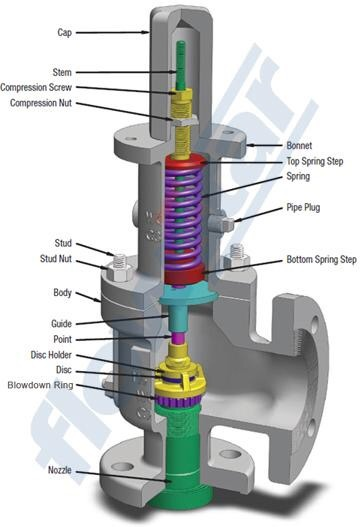
The basic spring loaded safety valve, referred to as ‘standard’ or ‘conventional’ is a simple, reliable self-acting device that provides overpressure protection.
The basic elements of the design consist of a right angle pattern valve body with the valve inlet connection, or nozzle, mounted on the pressure-containing system. The outlet connection may be screwed or flanged for connection to a piped discharge system. However, in some applications, such as compressed air systems, the safety valve will not have an outlet connection, and the fluid is vented directly to the atmosphere.
The valve inlet (or approach channel) design can be either a full-nozzle or a semi-nozzle type. A full-nozzle design has the entire ‘wetted’ inlet tract formed from one piece. The approach channel is the only part of the safety valve that is exposed to the process fluid during normal operation, other than the disc, unless the valve is discharging.
Conversely, the semi-nozzle design consists of a seating ring fitted into the body, the top of which forms the seat of the valve. The advantage of this arrangement is that the seat can easily be replaced, without replacing the whole inlet.
The disc is held against the nozzle seat (under normal operating conditions) by the spring, which is housed in an open or closed spring housing arrangement (or bonnet) mounted on top of the body. The discs used in rapid opening (pop type) safety valves are surrounded by a shroud, disc holder or huddling chamber which helps to produce the rapid opening characteristic.
The closing force on the disc is provided by a spring, typically made from carbon steel. The amount of compression on the spring is usually adjustable, using the spring adjuster, to alter the pressure at which the disc is lifted off its seat.Standards that govern the design and use of safety valves generally only define the three dimensions that relate to the discharge capacity of the safety valve, namely the flow (or bore) area, the curtain area and the discharge (or orifice) area.
Valves in which the flow area and not the curtain area determines the capacity are known as full lift valves. These valves will have a greater capacity than low lift or high lift valves.
Although the principal elements of a conventional safety valve are similar, the design details can vary considerably. In general, the DIN style valves (commonly used throughout Europe) tend to use a simpler construction with a fixed skirt (or hood) arrangement whereas the ASME style valves have a more complex design that includes one or two adjustable blowdown rings. The position of these rings can be used to fine-tune the overpressure and blowdown values of the valve.
For a given orifice area, there may be a number of different inlet and outlet connection sizes, as well as body dimensions such as centreline to face dimensions. Furthermore, many competing products, particularly of European origin have differing dimensions and capacities for the same nominal size.
An exception to this situation is found with steel ASME specification valves, which invariably follow the recommendations of the API Recommended Practice 526, where centreline to face dimensions, and orifice sizes are listed. The orifice area series are referred to by a letter. It is common for
For example, 2" x J x 3" and 3" x J x 4" are both valves which have the same size (‘J’) orifice, but they have differing inlet and outlet sizes as shown before and after the orifice letter respectively.
When the inlet static pressure rises above the set pressure of the safety valve, the disc will begin to lift off its seat. However, as soon as the spring starts to compress, the spring force will increase; this means that the pressure would have to continue to rise before any further lift can occur, and for there to be any significant flow through the valve.
The additional pressure rise required before the safety valve will discharge at its rated capacity is called the overpressure. The allowable overpressure depends on the standards being followed and the particular application. For compressible fluids, this is normally between 3% and 10%, and for liquids between 10% and 25%.
In order to achieve full opening from this small overpressure, the disc arrangement has to be specially designed to provide rapid opening. This is usually done by placing a shroud, skirt or hood around the disc. The volume contained within this shroud is known as the control or huddling chamber.
As lift begins, and fluid enters the chamber, a larger area of the shroud is exposed to the fluid pressure. Since the magnitude of the lifting force (F) is proportional to the product of the pressure (P) and the area exposed to the fluid (A); (F = P x A), the opening force is increased.
These combined effects allow the valve to achieve its designed lift within a relatively small percentage overpressure. For compressible fluids, an additional contributory factor is the rapid expansion as the fluid volume increases from a higher to a lower pressure area. This plays a major role in ensuring that the valve opens fully within the small overpressure limit. For liquids, this effect is more proportional and subsequently, the overpressure is typically greater; 25% is common.
Once normal operating conditions have been restored, the valve is required to close again, but since the larger area of the disc is still exposed to the fluid, the valve will not close until the pressure has dropped below the original set pressure. The difference between the set pressure and this reseating pressure is known as the ‘blowdown’, and it is usually specified as a percentage of the set pressure. For compressible fluids, the blowdown is usually less than 10%, and for liquids, it can be up to 20%.
The design of the shroud must be such that it offers both rapid opening and relatively small blowdown, so that as soon as a potentially hazardous situation is reached, any overpressure is relieved, but excessive quantities of the fluid are prevented from being discharged. At the same time, it is necessary to ensure that the system pressure is reduced sufficiently to prevent immediate reopening.
The blowdown rings found on most ASME type safety valves are used to make fine adjustments to the overpressure and blowdown values of the valves (see Figure 9.1.8). The lower blowdown (nozzle) ring is a common feature on many valves where the tighter overpressure and blowdown requirements require a more sophisticated designed solution. The upper blowdown ring is usually factory set and essentially takes out the manufacturing tolerances which affect the geometry of the huddling chamber.
The lower blowdown ring is also factory set to achieve the appropriate code performance requirements but under certain circumstances can be altered. When the lower blowdown ring is adjusted to its top position the huddling chamber volume is such that the valve will pop rapidly,
minimising the overpressure value but correspondingly requiring a greater blowdown before the valve re-seats. When the lower blowdown ring is adjusted to its lower position there is minimal restriction in the huddling chamber and a greater overpressure will be required before the valve is fully open but the blowdown value will be reduced.
For most countries, there are independent bodies who will examine the design and performance of a product range to confirm conformity with the relevant code or standard. This system of third party approval is very common for any safety related products and is often a customer requirement before purchase, or a requirement of their insurance company.
The actual requirements for approval will vary depending on the particular code or standard. In some cases, revalidation is necessary every few years, in others approval is indefinite as long as no significant design changes are made, in which case the approval authority must be notified, and re-approval sought. In the USA, the National Board of Boiler and Pressure Vessel Inspectors represents the US and Canadian government agencies empowered to assure adherence to code construction and repair of boilers and pressure vessels.
Standards relevant to safety valves vary quite considerably in format around the world, and many are sections within codes relevant to Boilers or Pressure Containing Vessels. Some will only outline performance requirements, tolerances and essential constructional detail, but give no guidance on dimensions, orifice sizes etc. Others will be related to installation and application.
For steam boiler applications there are very specific requirements for safety valve performance, demanded by national standards and often, insurance companies. Approval by an independent authority is often necessary, such as British Engine, TÜV or Lloyd’s Register.
Safety valves used in Europe are also subject to the standards associated with the Pressure Equipment Directive (PED). Being classified as ‘Safety accessories’, safety valves are considered as ‘Category 4’ equipment, which require the most demanding level of assessment within the PED regime. This can usually be met by the manufacturer having an ISO 9000 quality system and the safety valve design and performance certified by an officially recognised approval authority referred to as a ‘Notified Body’.

When you’re in the market for a pressure relief valve, a sales rep has probably asked you “what set pressure do you need?” This piece of information isrequiredto purchase a new pressure relief valve. You might have been able to retrieve this info from an old valve nameplate or look it up in your computer system, but what does the value mean?
Set pressure is the point at which a pressure relief valve is set to open under service conditions.It’s measured in pounds per square inch gauge (PSIG).
Set pressure sounds simple, right? Not always — there are rules and recommendations you should keep in mind when you’re determining the set pressure for pressure relief valves.
Identifying the process media, or service, of a valve is important to set pressure. If a valve has the correct set pressure but is used on the wrong application, there’s a chance the valve wouldn’t open when needed. This could cause the system or vessel to overpressure.
When the pressure in a system or vessel increases to a dangerous level, the pressure relief valve is there as the last line of defense. The valve opens when the inlet pressure exceeds the set pressure. When vessel pressure slightly exceeds the set pressure, fluid moves past the seating surface into the huddling chamber. The controlled pressure built up inside the huddling chamber will then overcome the spring force, causing the disc to lift and the valve to pop open.
After the valve opens, it will only close once the pressure has dropped a certain percentage below the set pressure. This percentage is referred to as blowdown, and will typically range anywhere from 4% to 10% depending on the applicable code.
Determining set pressure is just one thing you need to determine when you’re specifying a pressure relief or safety valve. If you need assistance finding the right-fit valve, contact us at (314) 665-1741.

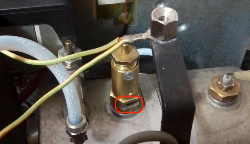
Thank you for your reply. We"re talking about the same thing, as the purpose of this part is to limit the pressure inside the boiler to a preset value. And this is done by relieving any extra pressure by pushing up the spring located inside the body of this valve.
The part on my machine is obviously adjustable, as screwing or unscrewing the upper cap adjusts the tension of the spring, therefore adjusting the operating pressure of the valve. However, this is not supposed to be done outside the factory, as proven by the anti-tamper screw.
1. Allow the boiler to get up to operating pressure (1.1-1.3), install some sort of temporary water retention container around the valve to avoid making a mess and then pull up the center pin using a chain and a ring. This will went some steam quite violently through the vents located near the base and may clean up the piston inside the valve.
2. If 1. fails to deliver results, mark the current position of the upper cap and unscrew it, paying attention to the number of turns required. Clean the little piston inside (apparently it should have some teflon cap, which is probably worn out -in which case finding a replacement is mandatory and may prove to be difficult).
The problem is that the seat inside the base piece is most likely gunked up with limescale and cleaning it while mounted on top of the boiler will be difficult.
P.S. I don"t have any means to double check the current working pressure, but the boiler also has a thermal probe designed to cut off power to the element if the boiler overheats. Since it"s not a common occurrence to see the pressurestat triggering but being overridden by the thermal probe , I guess the pressure reading of the machine"s gauge is quite accurate.
A. In a shaft design (Series RVT), a non-sticking solid PTFE shaft passes through three (3) U-cup seals which effectively isolates the liquid from the spring. An elastomer seat at the end of the shaft seals across the valve orifice.
B. In a diaphragm design of either PTFE or an elastomer the diaphragm becomes both the seal isolating the spring as well as the seal across the valve orifice.
Angle (90°) Porting Relief Valves have historically been the most popular design. Design and performance are the same. The benefit of a 90° angle pattern would be for simplifying the piping scheme by using the Relief Valve body in lieu of a 90° elbow. In-line valves can be installed anywhere in a straight piping run.
All styles are normally-closed and begin opening once the set pressure is reached. They use spring force to push down upon a shaft or diaphragm. The pressure setting is done manually by turning the adjusting bolt clockwise to raise the pressure setting, and counter-clockwise to lower it. This simply varies the compressive force of the internal spring across the valve orifice. The more it is compressed, the higher the set pressure will be.
When the inlet pressure reaches the set pressure, the force created by the inlet pressure is equal to the force exerted by the spring. Liquid then begins to trickle through the valve. As inlet pressure continues to increase, the valve opens farther, allowing more flow.
In addition to relieving excess/dangerous pressure from closed-top vessels or piping systems, these normally-closed valves provide system control benefits as shown. Depending upon the function performed, they are given different names, as in this relief valve diagram:
“Anti-Siphon Valve”– to prevent unwanted chemical siphoning through a pump; when negative pressure at a lower elevation could create a siphon and drain a tank. The valve is set to open at the desired pumping pressure, but seals tightly when a vacuum occurs downstream.
As shown in the application diagram above, this is a very versatile and widely utilized valve. Its compact size, ease of setting and re-adjustment and repeatability, all contribute to its popularity. There are Air-Loaded (aka. Dome Loaded) Relief Valves selectively available but require numerous accessory items (air regulators, filters, lubricators, etc.) for their operation.
For futher assistance with your specific application involving Relief Valves please contact our Technical Sales Dept. at (973) 256-3000 or E-mail us at info@plastomatic.com
This website is using a security service to protect itself from online attacks. The action you just performed triggered the security solution. There are several actions that could trigger this block including submitting a certain word or phrase, a SQL command or malformed data.

Safety valves are an arrangement or mechanism to release a substance from the concerned system in the event of pressure or temperature exceeding a particular preset limit. The systems in the context may be boilers, steam boilers, pressure vessels or other related systems. As per the mechanical arrangement, this one get fitted into the bigger picture (part of the bigger arrangement) called as PSV or PRV that is pressure safety or pressure relief valves.
This type of safety mechanism was largely implemented to counter the problem of accidental explosion of steam boilers. Initiated in the working of a steam digester, there were many methodologies that were then accommodated during the phase of the industrial revolution. And since then this safety mechanism has come a long way and now accommodates various other aspects.
These aspects like applications, performance criteria, ranges, nation based standards (countries like United States, European Union, Japan, South Korea provide different standards) etc. manage to differentiate or categorize this safety valve segment. So, there can be many different ways in which these safety valves get differentiated but a common range of bifurcation is as follows:
The American Society of Mechanical Engineers (ASME) I tap is a type of safety valve which opens with respect to 3% and 4% of pressure (ASME code for pressure vessel applications) while ASME VIII valve opens at 10% over pressure and closes at 7%. Lift safety valves get further classified as low-lift and full lift. The flow control valves regulate the pressure or flow of a fluid whereas a balanced valve is used to minimize the effects induced by pressure on operating characteristics of the valve in context.
A power operated valve is a type of pressure relief valve is which an external power source is also used to relieve the pressure. A proportional-relief valve gets opened in a relatively stable manner as compared to increasing pressure. There are 2 types of direct-loaded safety valves, first being diaphragms and second: bellows. diaphragms are valves which spring for the protection of effects of the liquid membrane while bellows provide an arrangement where the parts of rotating elements and sources get protected from the effects of the liquid via bellows.
In a master valve, the operation and even the initiation is controlled by the fluid which gets discharged via a pilot valve. Now coming to the bigger picture, the pressure safety valves based segment gets classified as follows:
So all in all, pressure safety valves, pressure relief valves, relief valves, pilot-operated relief valves, low pressure safety valves, vacuum pressure safety valves etc. complete the range of safety measures in boilers and related devices.
Safety valves have different discharge capacities. These capacities are based on the geometrical area of the body seat upstream and downstream of the valve. Flow diameter is the minimum geometrical diameter upstream and downstream of the body seat.
The nominal size designation refers to the inlet orifice diameter. A safety Valve"s theoretical flowing capacity is the mass flow through an orifice with the same cross-sectional area as the valve"s flow area. This capacity does not account for the flow losses caused by the valve. The actual capacity is measured, and the certified flow capacity is the actual flow capacity reduced by 10%.
A safety valve"s discharge capacity is dependent on the set pressure and position in a system. Once the set pressure is calculated, the discharge capacity must be determined. Safety valves may be oversized or undersized depending on the flow throughput and/or the valve"s set pressure.
The actual discharge capacity of a safety valve depends on the type of discharge system used. In liquid service, safety valves are generally automatic and direct-pressure actuated.
A safety valve is used to protect against overpressure in a fluid system. Its design allows for a lift in the disc, indicating that the valve is about to open. When the inlet pressure rises above the set pressure, the guide moves to the open position, and media flows to the outlet via the pilot tube. Once the inlet pressure falls below the set pressure, the main valve closes and prevents overpressure. There are five criteria for selecting a safety valve.
The first and most basic requirement of a safety valve is its ability to safely control the flow of gas. Hence, the valve must be able to control the flow of gas and water. The valve should be able to withstand the high pressures of the system. This is because the gas or steam coming from the boiler will be condensed and fill the pipe. The steam will then wet the safety valve seat.
The other major requirement for safety valves is their ability to prevent pressure buildup. They prevent overpressure conditions by allowing liquid or gas to escape. Safety valves are used in many different applications. Gas and steam lines, for example, can prevent catastrophic damage to the plant. They are also known as safety relief valves. During an emergency, a safety valve will open automatically and discharge gas or liquid pressure from a pressurized system, preventing it from reaching dangerous levels.
The discharge capacity of a safety valve is based on its orifice area, set pressure, and position in the system. A safety valve"s discharge capacity should be calculated based on the maximum flow through its inlet and outlet orifice areas. Its nominal size is often determined by manufacturer specifications.
Its discharge capacity is the maximum flow through the valve that it can relieve, based on the maximum flow through each individual flow path or combined flow path. The discharge pressure of the safety valve should be more than the operating pressure of the system. As a thumb rule, the relief pressure should be 10% above the working pressure of the system.
It is important to choose the discharge capacity of a safety valve based on the inlet and output piping sizes. Ideally, the discharge capacity should be equal to or greater than the maximum output of the system. A safety valve should also be installed vertically and into a clean fitting. While installing a valve, it is important to use a proper wrench for installation. The discharge piping should slope downward to drain any condensate.
The discharge capacity of a safety valve is measured in a few different ways. The first is the test pressure. This gauge pressure is the pressure at which the valve opens, while the second is the pressure at which it re-closes. Both are measured in a test stand under controlled conditions. A safety valve with a test pressure of 10,000 psi is rated at 10,000 psi (as per ASME PTC25.3).
The discharge capacity of a safety valve should be large enough to dissipate a large volume of pressure. A small valve may be adequate for a smaller system, but a larger one could cause an explosion. In a large-scale manufacturing plant, safety valves are critical for the safety of personnel and equipment. Choosing the right valve size for a particular system is essential to its efficiency.
Before you use a safety valve, you need to know its discharge capacity. Here are some steps you need to follow to calculate the discharge capacity of a safety valve.
To check the discharge capacity of a safety valve, the safety valve should be installed in the appropriate location. Its inlet and outlet pipework should be thoroughly cleaned before installation. It is important to avoid excessive use of PTFE tape and to ensure that the installation is solid. The safety valve should not be exposed to vibration or undue stress. When mounting a safety valve, it should be installed vertically and with the test lever at the top. The inlet connection of the safety valve should be attached to the vessel or pipeline with the shortest length of pipe. It must not be interrupted by any isolation valve. The pressure loss at the inlet of a safety valve should not exceed 3% of the set pressure.
The sizing of a safety valve depends on the amount of fluid it is required to control. The rated discharge capacity is a function of the safety valve"s orifice area, set pressure, and position in the system. Using the manufacturer"s specifications for orifice area and nominal size of the valve, the capacity of a safety valve can be determined. The discharge flow can be calculated using the maximum flow through the valve or the combined flows of several paths. When sizing a safety valve, it"s necessary to consider both its theoretical and actual discharge capacity. Ideally, the discharge capacity will be equal to the minimum area.
To determine the correct set pressure for a safety valve, consider the following criteria. It must be less than the MAAP of the system. Set pressure of 5% greater than the MAAP will result in an overpressure of 10%. If the set pressure is higher than the MAAP, the safety valve will not close. The MAAP must never exceed the set pressure. A set pressure that is too high will result in a poor shutoff after discharge. Depending on the type of valve, a backpressure variation of 10% to 15% of the set pressure cannot be handled by a conventional valve.

Curtiss-Wright"s selection of Pressure Relief Valves comes from its outstanding product brands Farris and Target Rock. We endeavor to support the whole life cycle of a facility and continuously provide custom products and technologies. Boasting a reputation for producing high quality, durable products, our collection of Pressure Relief Valves is guaranteed to provide effective and reliable pressure relief.
While some basic components and activations in relieving pressure may differ between the specific types of relief valves, each aims to be 100% effective in keeping your equipment running safely. Our current range includes numerous valve types, from flanged to spring-loaded, threaded to wireless, pilot operated, and much more.
A pressure relief valve is a type of safety valve designed to control the pressure in a vessel. It protects the system and keeps the people operating the device safely in an overpressure event or equipment failure.
A pressure relief valve is designed to withstand a maximum allowable working pressure (MAWP). Once an overpressure event occurs in the system, the pressure relief valve detects pressure beyond its design"s specified capability. The pressure relief valve would then discharge the pressurized fluid or gas to flow from an auxiliary passage out of the system.
Below is an example of one of our pilot operated pressure relief valves in action; the cutaway demonstrates when high pressure is released from the system.
Air pressure relief valves can be applied to a variety of environments and equipment. Pressure relief valves are a safety valve used to keep equipment and the operators safe too. They"re instrumental in applications where proper pressure levels are vital for correct and safe operation. Such as oil and gas, power generation like central heating systems, and multi-phase applications in refining and chemical processing.
At Curtiss-Wright, we provide a range of different pressure relief valves based on two primary operations – spring-loaded and pilot operated. Spring-loaded valves can either be conventional spring-loaded or balanced spring-loaded.
Spring-loaded valves are programmed to open and close via a spring mechanism. They open when the pressure reaches an unacceptable level to release the material inside the vessel. It closes automatically when the pressure is released, and it returns to an average operating level. Spring-loaded safety valves rely on the closing force applied by a spring onto the main seating area. They can also be controlled in numerous ways, such as a remote, control panel, and computer program.
Pilot-operated relief valves operate by combining the primary relieving device (main valve) with self-actuated auxiliary pressure relief valves, also known as the pilot control. This pilot control dictates the opening and closing of the main valve and responds to system pressure. System pressure is fed from the inlet into and through the pilot control and ultimately into the main valve"s dome. In normal operating conditions, system pressure will prevent the main valve from opening.
The valves allow media to flow from an auxiliary passage and out of the system once absolute pressure is reached, whether it is a maximum or minimum level.
When the pressure is below the maximum amount, the pressure differential is slightly positive on the piston"s dome size, which keeps the main valve in the closed position. When system pressure rises and reaches the set point, the pilot will cut off flow to the dome, causing depressurization in the piston"s dome side. The pressure differential has reversed, and the piston will rise, opening the main valve, relieving pressure.
When the process pressure decreases to a specific pressure, the pilot closes, the dome is repressurized, and the main valve closes. The main difference between spring-loaded PRVs and pilot-operated is that a pilot-operated safety valve uses pressure to keep the valve closed.
Pilot-operated relief valves are controlled by hand and are typically opened often through a wheel or similar component. The user opens the valve when the gauge signifies that the system pressure is at an unsafe level; once the valve has opened and the pressure has been released, the operator can shut it by hand again.
Increasing pressure helps to maintain the pilot"s seal. Once the setpoint has been reached, the valve opens. This reduces leakage and fugitive emissions.
At set pressure the valve snaps to full lift. This can be quite violent on large pipes with significant pressure. The pressure has to drop below the set pressure in order for the piston to reseat.
The pilot is designed to open gradually, so that less of the system fluid is lost during each relief event. The piston lifts in proportion to the overpressure.
At Curtiss-Wright we also provide solutions for pressure relief valve monitoring. Historically, pressure relief valves have been difficult or impossible to monitor. Our SmartPRV features a 2600 Series pressure relief valve accessorized with a wireless position monitor that alerts plant operators during an overpressure event, including the time and duration.
There are many causes of overpressure, but the most common ones are typically blocked discharge in the system, gas blowby, and fire. Even proper inspection and maintenance will not eliminate the occurrence of leakages. An air pressure relief valve is the only way to ensure a safe environment for the device, its surroundings, and operators.
A PRV and PSV are interchangeable, but there is a difference between the two valves. A pressure release valve gradually opens when experiencing pressure, whereas a pressure safety valve opens suddenly when the pressure hits a certain level of over pressurization. Safety valves can be used manually and are typically used for a permanent shutdown. Air pressure relief valves are used for operational requirements, and they gently release the pressure before it hits the maximum high-pressure point and circulates it back into the system.
Pressure relief valves should be subject to an annual test, one per year. The operator is responsible for carrying out the test, which should be done using an air compressor. It’s imperative to ensure pressure relief valves maintain their effectiveness over time and are checked for signs of corrosion and loss of functionality. Air pressure relief valves should also be checked before their installation, after each fire event, and regularly as decided by the operators.
Direct-acting solenoid valves have a direct connection with the opening and closing armature, whereas pilot-operated valves use of the process fluid to assist in piloting the operation of the valve.
A control valve works by varying the rate of fluid passing through the valve itself. As the valve stem moves, it alters the size of the passage and increases, decreases or holds steady the flow. The opening and closing of the valve is altered whenever the controlled process parameter does not reach the set point.
Control valves are usually at floor level or easily accessible via platforms. They are also located on the same equipment or pipeline as the measurement and downstream or flow measurements.
An industrial relief valve is designed to control or limit surges of pressure in a system, most often in fluid or compressed air system valves. It does so as a form of protection for the system and defending against instrument or equipment failure. They are usually present in clean water industries.
A PRV is often referred to as a pressure relief valve, which is also known as a PSV or pressure safety valve. They are used interchangeably throughout the industry depending on company standards.
(a) Qualifications of individual who adjusts. Safety relief valves shall be set and adjusted by a competent person who is thoroughly familiar with the construction and operation of the valve being set.
(b) Opening pressures. At least one safety relief valve shall be set to open at a pressure not exceeding the MAWP. Safety relief valves shall be set to open at pressures not exceeding 6 psi above the MAWP.
(c) Setting procedures. When setting safety relief valves, two steam gauges shall be used, one of which must be so located that it will be in full view of the persons engaged in setting such valves; and if the pressure indicated by the gauges varies more than 3 psi they shall be removed from the boiler, tested, and corrected before the safety relief valves are set. Gauges shall in all cases be tested immediately before the safety relief valves are set or any change made in the setting. When setting safety relief valves, the water level shall not be higher than
(d) Labeling of lowest set pressure. The set pressure of the lowest safety relief valve shall be indicated on a tag or label attached to the steam gauge so that it may be clearly read while observing the steam gauge.

The power supply to the electrical control system shall be from a two-wire branch circuit that has a grounded conductor, or from an isolation transformer with a two-wire secondary. Where an isolation transformer is provided, one conductor of the secondary winding shall be grounded. Control voltage shall not exceed 150 volts nominal, line to line. Control and limit devices shall interrupt the ungrounded side of the circuit. A means of manually disconnecting the control circuit shall be provided and controls shall be arranged so that when deenergized, the burner shall be inoperative. Such disconnecting means shall be capable of being locked in the off position and shall be provided with ready access.
A pressure safety valve actuated by inlet static pressure and characterized by rapid opening or rapid popping action. This safety valve is tight shut-off and is for safety only. Meets ASME SEC. VIII (Not a Fulflo valve)
A spring loaded pressure relief valve, actuated by the static pressure upstream of the valve. The valve opens normally in proportion to the increase in pressure over the set pressure. (Fulflo)
A pressure relief valve characterized by rapid opening or pop-action in direct proportion to the pressure increase, depending on the application. (Fulflo)
The pressure existing at the outlet of a pressure relief valve, due to the pressure in the discharge system. The pressure can be constant or variable. It is the sum of the superimposed and build-up pressure.
The pressure existing at the outlet of the relief device at the time the device is required to operate. It is a result of pressure in the discharge system coming from another source. This pressure may be constant or variable.
Fulflo was established in 1912 and is celebrating its 100th anniversary. Located in Blanchester, OH, Fulflo was incorporated in 1933 under its present name and trademark. Patents for the original guided piston, direct acting relief valve were obtained in 1935, coinciding with the onset of fluid power systems. The need for providing large flows without excessive bulk was met by the pilot-valve-control relief valve which was patented in 1943.
Fulflo parts and valves are used in oil and gas refineries, are essential to the military, including ships and aircraft carriers, and amusement roller coaster rides.


 8613371530291