
how to calculate cdtp in safety valve supplier
Built-up back pressure is the backpressure generated due to pressure losses at the outlet of an open relief valve when it is discharging. This pressure depends on the pressure of the vent header downstream to the relief valve and the relieving flowrate which is being discharged. The built-up backpressure is the pressure in the vent header plus pressure drop in the line from relief valve to vent header, when the valve is discharging at full capacity.
For certain relief valve designs, the backpressure on the valve acts as a closing force and can affect the opening pressure for the valve. ‘Conventional’ valves are highly susceptible to this effect and hence not used in applications where high backpressure is expected. ‘Balanced Bellows’ and ‘Pilot Operated’ relief valves relatively shielded from effects of high backpressure.
For some relief valves (especially conventional type relief valves), the opening of the valve is affected by backpressure seen by the valve. If the backpressure seen by such relief valves is higher than atmospheric, then it has to be designed to open at a lower differential pressure value than the relief valve set pressure minus atmospheric pressure. However when the relief valve is tested before installation, it only sees atmospheric pressure as backpressure. Hence to open this relief valve at same differential pressure value, the set point pressure for opening the valve has to be lower than original design set point pressure. This set point value is known as cold differential test pressure (CDTP).
For pilot operated and balanced bellows type relief valves, effect of backpressure on valve opening characteristics is very low and hence CDTP is the same as the original design set point pressure value.

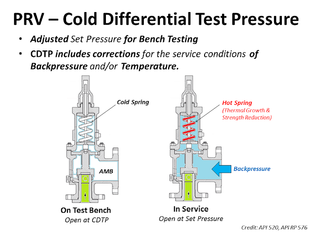
The conditions at which PRV is set to operate on a test stand could be different from the actual service conditions under which a PRV is required to open in the plant.
As we had discussed the backpressure that relief valve faces in a closed system would not be present during testing in the shop and this needs to be compensated for conventional relief valves.
However as discussed above the parameter of Temperature correction factor would still be applicable to Bellows and pilot-operated relief valve if the PRV temperature is significantly different from that of ambient temperature.
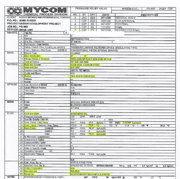
Project Scenario : A Relief valve of Dresser 1900 Series (Conventional relief valve) valve is required to open at 800 Psig where the service temperature is 400°F and backpressure is 100 Psig.
Further for Convetional Valve API-521 paragraph 4.2.3.3 A convetional PRV Operating with a constant superimposed back pressure normally required a correction factor to compensate for the back pressure. In this case the required set pressure minus superimposed back pressure is equal to CDTP. This change account for the addtional closing force exerted on the valve disk by back pressure.
Now, we have to add this pressure for back pressure consideration or valve is tested based on CDTP, But if we tested based on CDTP than this is less that the set pressure as CDTP is Set Pressure - Superimposed back pressure.
(100Mbs) Over 2000 Questions and Answers. Full API document, codes, questions on each applicable Code/Section (1-2 months) prior to participate in Prometric examination. Full Training presentations for self learning. Bonus: API 510, 571 Flash Cards, PSV notes – excel files.
The Cold Differential Test Pressure (CDTP)of thePressure Relief Valve (PRV) is a set pressure that is adjusted to be used for the PRV (Bench Testing). Because in actual use conditions, the PRV may be affected by the Backpressure. And the operating temperature. Therefore, when testing at room temperature and without backpressure, it is necessary to adjust the set pressure to compensate for these factors. In other words, the shop test pressure = CDTP.
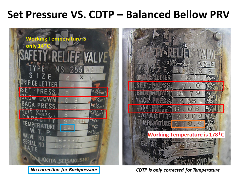
An example of aCold Differential Test Pressure (CDTP)with abackpressure (superimposed)effect. In this case, CDTP is equal to Set Pressure minus Backpressure.
An example of aCold Differential Test Pressure (CDTP)with different temperature compensations for use and testing. And an example ofCDTP that has been adjusted to compensate for both Backpressure (Superimposed) and temperatureeffects.
Test Stand or Test Bench is a set of equipment used for Pressure Relief Valve (PRV) in Pop Test (Set Pressure Test), Blowdown and Seat Tightness Test (Leakage Test)
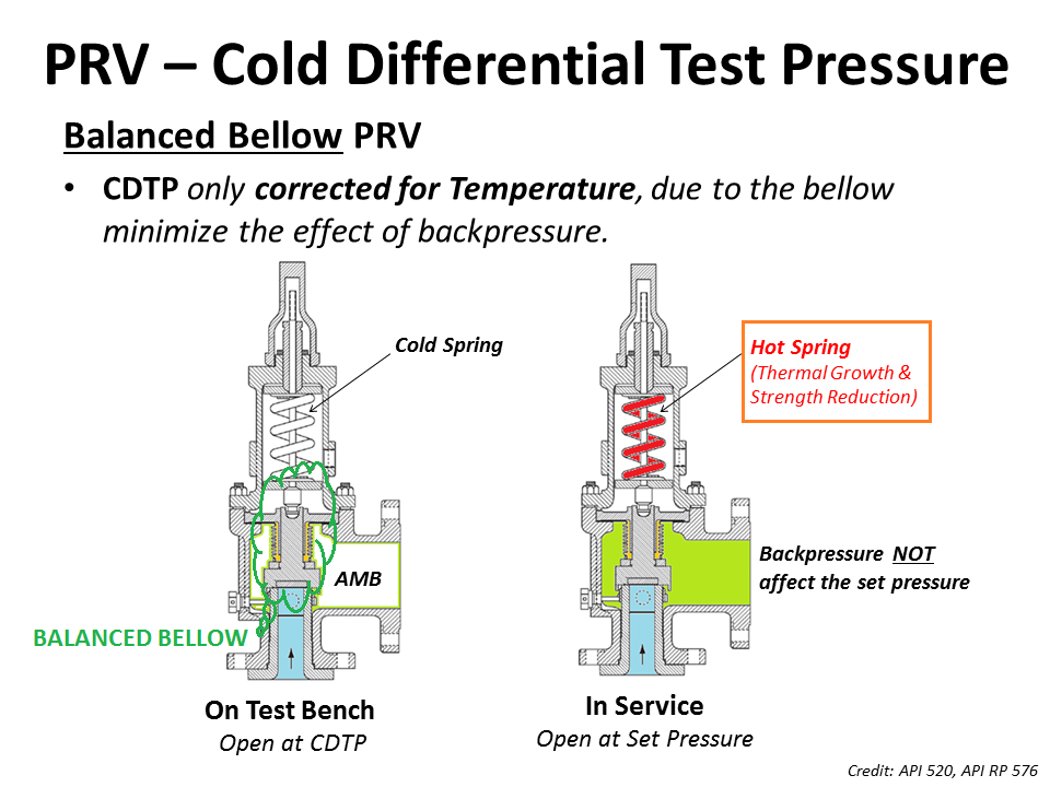
As for theBalanced Bellow Pressure Relief Valve, which has a bellowfor reducing the impact of theBackpressure, the Cold Differential Test Pressure (CDTP) of the Balanced Bellow Type PRV will compensate only for the impact of different temperatures between the Shop Test and In-service.
The National Board strives to keep information in the hands of website users. Provided here are more than 70 Technical Articles previously published in the National Board BULLETINand/or from the proceedings of past General Meetings.
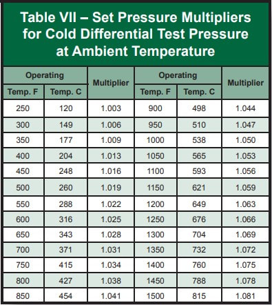
NATIONAL BOARD tells how to calculate the CDTP for a PRD taking into account a temperature differential and a back pressure, CDTP is not more than the difference of the SET PRESSURE minus the superpositions exerted by the effect of the temperature and the back pressure of a valve of conventional design (without bellows). By the way, the temperature correction is given by a multiplying factor that will depend on the quality of the internals of each valve and this is supplied by the manufacturer"s brand. For example DRESSER has its own tables of multiplying factors
www.controlglobal.com is using a security service for protection against online attacks. An action has triggered the service and blocked your request.
Please try again in a few minutes. If the issue persist, please contact the site owner for further assistance. Reference ID IP Address Date and Time 49aa4de84ffe7587c78dee4984bc4222 63.210.148.230 01/26/2023 01:18 PM UTC

Did you know, under certain circumstances, you need to verify if the Cold Differential Test Pressure (CDTP) is properly compensated for the superimposed backpressure from the flare header?
Have you come across a conventional pressure relief valve relieving to a flare header? Did you know that, under certain circumstances, you need to verify if the Cold Differential Test Pressure (CDTP) is properly compensated for the superimposed backpressure from the flare header?
API 520 Part I, Ninth Edition, Section 5.3.2.1 says, "Superimposed backpressure at the outlet of a conventional spring-loaded PRV acts to hold the valve disc closed with a force additive to the spring force. The actual spring setting can be reduced by an amount equal to the superimposed backpressure to compensate for this."
It further goes on to say in Sections 5.3.2.2 & 5.3.2.3, "Balanced spring-loaded or pilot-operated PRVs should be considered if the superimposed backpressure is variable. However, if the amount of variable superimposed backpressure is small, a conventional valve could be used provided:
For example, conventional valves are often used when the outlet is piped into a relief header without compensating the set pressures for the superimposed backpressure caused by other relieving devices. This approach can be used provided the allowable accumulation is not exceeded during the release.

When selecting spring loaded safety valves, an accurate knowledge and consideration of the specific operating conditions are vital to ensure that these devices work reliably. As optimal resource use becomes an increasingly relevant criterion, plant owners focus particular attention on components that can be depended on absolutely – even at their physical limits.
In the design of a safety valve, the existence of a backpressure must be considered in addition to the usual parameters for dimensioning. In this present report, the function of a safety valve is intended to be shown when a constant superimposed backpressure is present in the discharge and thus acts against the direction of opening of the safety valve.
A spring loaded safety valve is a valve which allows a defined amount of fluid to be discharged automatically – unaided by any form of energy other than the medium itself – in order to prevent a predetermined safe pressure from being exceeded. It is designed in such a way that it closes as soon as normal conditions are restored, so that no more fluid exits [2, p. 4]. As the final protective device in the technical system, it plays a special role and must be depended on to work absolutely reliably. Careful design and sizing by the systems engineer as well as expert execution of the entire installation are essential for proper functioning. As far as the safety valve itself is concerned, it is important that the spring(s) and disc (closure component) can perform their work (lift) undisturbed. If this is not the case, in other words if the required lift is restricted, impeded or blocked, delayed actuation, flutter and reduced performance could be the outcome – in short, operation outside the limits allowed by the regulations. The safety and reliability of the installation as a whole would be jeopardised. All safety valves approved under European or American regulations are subject to strict standards and component monitoring procedures. The safety valves manufactured by ARI-Armaturen are approved, for example, to DIN EN ISO 4126 [5] and ASME VIII Div. 1 [7].
In other words, the valve opens if the pressure and hence the force underneath the disc in the pressure vessel is greater than the force which presses the disc against the seat (nozzle). A basic distinction is made here between two different types of actuation, namely sudden (rapid opening) and almost continuous (but not necessarily linear opening) [2, p. 4].
Whereas the operational behaviour of spring loaded safety valves with a built-up backpres-sure has already been the object of a detailed study in [1], this paper examines their operational behaviour with a preset, constant superimposed backpressure and a cold differential test pressure (CDTP) setting (Figure 1). Plant planners and owners are particularly interested in answers to the following two questions:
What effect does a constant superimposed backpressure have on the safety valve’s functionality (opening pressure difference, closing pressure difference), performance and leakproofness and to what extent does a cold differential test pressure setting influence the valve’s functional characteristic?
In the context of safety valves, we differentiate between built-up backpressure and superimposed backpressure. Amongst other things, the existence of backpressure is conditional on the use of a metal bellow. The built-up backpressure is the excess pressure in the outlet pipe of the safety valve which is built up during the blow-off phase (opening) and is therefore variable. The superimposed backpressure is the excess pressure which is already present in the outlet pipe of the safety valve before the blow-off phase begins. It can be either constant or variable (Figure 2).
This additional force must be taken into account when setting the compression spring, which requires correspondingly less preload [6, p. 17]. The safety valve will otherwise be actuated at too high a pressure, namely at the sum of equation (3).
The procedure described in section background is the norm when sizing and setting American safety valves to API/ASME [6, p. 25]; it is referred to as the „CDTP setting“:
According to the European regulatory framework provided by DIN EN ISO 4126 [2, p. 5], the CDTP may include a correction for backpres-sure and temperature. Extensive measurements to determine this have been carried out on an air dynamometer at ARI-Armaturen (refer to section results).
The backpressure can be compensated by installing a metal bellows (Figure 3). The optimal effect is achieved if the mean bellows diameter corresponds as closely as possible to the mean seat diameter of the safety valve. A bellows is always required if the superimposed backpressure FBPsuperimposed is variable because a variable backpressure will otherwise cause the set pressure to change constantly.
The operational behaviour must be assessed using the parameters described in the recognised standards [2, 3]. The backpressure ratio, which determines whether critical or subcritical operating conditions apply, is crucial here. Critical operation means that if the pressure behind the valve seat drops further, the mass flow no longer increases [3, p. 7]. Under subcritical flow conditions, therefore, the term must be multiplied by the correction factor Kb in order to calculate the theoretical mass flow. According to [3, p. 8 and 23], Kb can be either calculated or read off, it has a direct influence on the determination of the coefficient of discharge Kd (or Kdr) [3, p. 7ff].
The safety valve has been adjusted to the stated pressure (Definition: Initial Audible). Then the constant backpressure was increased and accounted for as a percentage of each explains the measured values. To reduce the time for rebuild on an adjustment of the valve (clamping bolt) and thus the CDTP correction has been omitted. Additionally, it was kept almost nearly constant through the use of an automatic control valve in the discharge line of the backpressure to the set value. The influence of built-up backpressure was negligible. The results are accordingly plotted in section results (extract 5 bar), based on equation (3) and the set pressure should correspond to the sum of Fspringforce + FBPsuperimposed. Three measurements were performed for each setting; the mean value in each case was taken as a basis for the results shown in figure 5 to 8.
The safety valve responds within the allowed limits, thus despite the presence of constant superimposed backpressure and a setting according to (3) correctly, the general function characteristic of the response is not adversely affected. Despite the constant superimposed backpressure, the valve reaches its full stroke. In the version without metal bellows, the opening pressure difference increases linearly to the backpressure ratio (Figure 6), but is within the specified range, with metal bellows it is almost constant despite increasing backpressure ratio (Figure 8). A constant backpressure and the resulting adjustment according to (4) affects the working behaviour of the safety valve in particular to the effect that the blowdown changed (it decreases linearly to the backpressure ratio (Figure 8)). This means there is a risk that the safety valve with increasing backpressure ratio or a higher opening pressure after the response no longer closes reliably and has a permanent, „creeping“ leakage. In the design and sizing of safety valves with constant backpressure of the concrete application and the operating conditions are therefore always taken into account. For this purpose, the respective manufacturer should be contacted in particular to take into account the operating limits and changing operating parameters in the selection and interpretation.


 8613371530291