
how to calculate cdtp in safety valve in stock
Further for Convetional Valve API-521 paragraph 4.2.3.3 A convetional PRV Operating with a constant superimposed back pressure normally required a correction factor to compensate for the back pressure. In this case the required set pressure minus superimposed back pressure is equal to CDTP. This change account for the addtional closing force exerted on the valve disk by back pressure.
Now, we have to add this pressure for back pressure consideration or valve is tested based on CDTP, But if we tested based on CDTP than this is less that the set pressure as CDTP is Set Pressure - Superimposed back pressure.
(100Mbs) Over 2000 Questions and Answers. Full API document, codes, questions on each applicable Code/Section (1-2 months) prior to participate in Prometric examination. Full Training presentations for self learning. Bonus: API 510, 571 Flash Cards, PSV notes – excel files.
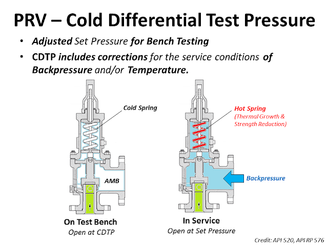
The Cold Differential Test Pressure (CDTP)of thePressure Relief Valve (PRV) is a set pressure that is adjusted to be used for the PRV (Bench Testing). Because in actual use conditions, the PRV may be affected by the Backpressure. And the operating temperature. Therefore, when testing at room temperature and without backpressure, it is necessary to adjust the set pressure to compensate for these factors. In other words, the shop test pressure = CDTP.
An example of aCold Differential Test Pressure (CDTP)with abackpressure (superimposed)effect. In this case, CDTP is equal to Set Pressure minus Backpressure.
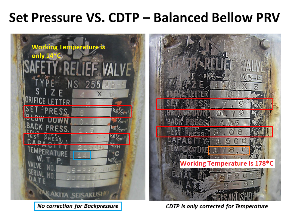
An example of aCold Differential Test Pressure (CDTP)with different temperature compensations for use and testing. And an example ofCDTP that has been adjusted to compensate for both Backpressure (Superimposed) and temperatureeffects.
Test Stand or Test Bench is a set of equipment used for Pressure Relief Valve (PRV) in Pop Test (Set Pressure Test), Blowdown and Seat Tightness Test (Leakage Test)
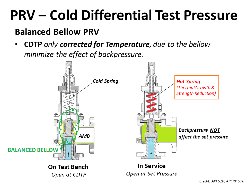
As for theBalanced Bellow Pressure Relief Valve, which has a bellowfor reducing the impact of theBackpressure, the Cold Differential Test Pressure (CDTP) of the Balanced Bellow Type PRV will compensate only for the impact of different temperatures between the Shop Test and In-service.
Built-up back pressure is the backpressure generated due to pressure losses at the outlet of an open relief valve when it is discharging. This pressure depends on the pressure of the vent header downstream to the relief valve and the relieving flowrate which is being discharged. The built-up backpressure is the pressure in the vent header plus pressure drop in the line from relief valve to vent header, when the valve is discharging at full capacity.
For certain relief valve designs, the backpressure on the valve acts as a closing force and can affect the opening pressure for the valve. ‘Conventional’ valves are highly susceptible to this effect and hence not used in applications where high backpressure is expected. ‘Balanced Bellows’ and ‘Pilot Operated’ relief valves relatively shielded from effects of high backpressure.
For some relief valves (especially conventional type relief valves), the opening of the valve is affected by backpressure seen by the valve. If the backpressure seen by such relief valves is higher than atmospheric, then it has to be designed to open at a lower differential pressure value than the relief valve set pressure minus atmospheric pressure. However when the relief valve is tested before installation, it only sees atmospheric pressure as backpressure. Hence to open this relief valve at same differential pressure value, the set point pressure for opening the valve has to be lower than original design set point pressure. This set point value is known as cold differential test pressure (CDTP).
For pilot operated and balanced bellows type relief valves, effect of backpressure on valve opening characteristics is very low and hence CDTP is the same as the original design set point pressure value.
Did you know, under certain circumstances, you need to verify if the Cold Differential Test Pressure (CDTP) is properly compensated for the superimposed backpressure from the flare header?
Have you come across a conventional pressure relief valve relieving to a flare header? Did you know that, under certain circumstances, you need to verify if the Cold Differential Test Pressure (CDTP) is properly compensated for the superimposed backpressure from the flare header?
API 520 Part I, Ninth Edition, Section 5.3.2.1 says, "Superimposed backpressure at the outlet of a conventional spring-loaded PRV acts to hold the valve disc closed with a force additive to the spring force. The actual spring setting can be reduced by an amount equal to the superimposed backpressure to compensate for this."
It further goes on to say in Sections 5.3.2.2 & 5.3.2.3, "Balanced spring-loaded or pilot-operated PRVs should be considered if the superimposed backpressure is variable. However, if the amount of variable superimposed backpressure is small, a conventional valve could be used provided:
For example, conventional valves are often used when the outlet is piped into a relief header without compensating the set pressures for the superimposed backpressure caused by other relieving devices. This approach can be used provided the allowable accumulation is not exceeded during the release.

The conditions at which PRV is set to operate on a test stand could be different from the actual service conditions under which a PRV is required to open in the plant.
As we had discussed the backpressure that relief valve faces in a closed system would not be present during testing in the shop and this needs to be compensated for conventional relief valves.
However as discussed above the parameter of Temperature correction factor would still be applicable to Bellows and pilot-operated relief valve if the PRV temperature is significantly different from that of ambient temperature.
Project Scenario : A Relief valve of Dresser 1900 Series (Conventional relief valve) valve is required to open at 800 Psig where the service temperature is 400°F and backpressure is 100 Psig.

Pressure at which a pressure-relief valve is adjusted to open on the test stand. NOTE The cold differential test pressure includes corrections for the service conditions of back pressure or temperature or both.

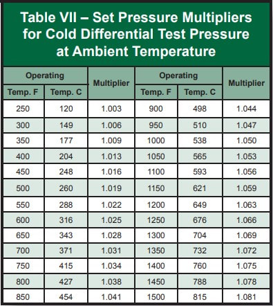
NATIONAL BOARD tells how to calculate the CDTP for a PRD taking into account a temperature differential and a back pressure, CDTP is not more than the difference of the SET PRESSURE minus the superpositions exerted by the effect of the temperature and the back pressure of a valve of conventional design (without bellows). By the way, the temperature correction is given by a multiplying factor that will depend on the quality of the internals of each valve and this is supplied by the manufacturer"s brand. For example DRESSER has its own tables of multiplying factors
www.controlglobal.com is using a security service for protection against online attacks. An action has triggered the service and blocked your request.
Please try again in a few minutes. If the issue persist, please contact the site owner for further assistance. Reference ID IP Address Date and Time 49aa4de84ffe7587c78dee4984bc4222 63.210.148.230 01/26/2023 01:17 PM UTC

Proper repair of a Pressure Relief Valve starts with knowing the PRV Manufacturer and Model Number. All Pressure Relief Valves are similar, but being aware of the differences is the first step to being a qualified PRV Technician. Identification and interpretation of Nameplate Data is the basis for a proper repair.
The Manufactureris the PRV Technician"s source for information and replacement parts. Both are vital to a proper "VR" Repair. The Manufacturer or his authorized Assembler can provide the correct Maintenance Manual for Critical Dimensions and Repair Procedures as well as Original Manufacturer"s Parts for replacement.
The Model Number may be extremely long. However, each character is relevant to proper repair. It is important to determine that the PRV is the correct configuration for the application. When a PRV for Liquid service is placed in Air/Gas service, there is a high probability that the spring is the incorrect range for the service and the PRV may exhibit long blowdown when required to open due to a pressure excursion. Conversely, an Air/Gas Service PRV installed in Liquid service may have a spring that is several ranges too high for a Liquid application. The result can be inadequate lift (travel of the disc in the opening direction) during an overpressure event. This could result in reduced capacity thereby causing failure to properly protect the system. One character in the PRV Type or Model Number could make the difference between success and failure of a pressurized system.
The Model Number informs the Repair Technician of the PRV Series. This indicates suitability for the application and indicates which Maintenance Manual will be needed. Further, the Model Number typically indicates the Orifice Size of the PRV. The orifice size drives the selection of the Critical Dimensions to be measured and recorded during Inspection. Included in the Model Number may be a character that indicates the presence of a Bellows or an O-Ring Seat. Cap and Lever Designs may also be indicated in the Model Number, along with Materials (Internals & Body/Bonnet). Typically, the Model Number indicates the Inlet Pressure and Temperature Range of the PRV.
The Inlet Size, Pressure Rating and Connection (Flanged or Threaded, Male or Female) are vital for proper testing of the PRV. The PRV Technician must be able to select the proper Test Fixture for mounting the PRV on the Test Bench.
Set Pressure is necessary for selection of the proper Test Gauge and Test Bench Pressure Rating. Set Pressure and ASME Certification Mark (or Supplanted Code Stamping) lets the PRV Technician calculate the allowable ASME Code Set Pressure Tolerance.
CDTP(Cold Differential Test Pressure) may be stamped on PRVs certified to ASME Section VIII service. CDTP compensates for Elevated Temperature and/or Back Pressure. CDTP is an item of Nameplate Data that is much misunderstood. Simply put, the use of a CDTP means that the PRV Technician does not have to recreate "In-Service" conditions at the Test Bench. Elevated system temperature and/or Back Pressure can be accounted for during testing by application of the CDTP.
Capacity is important because the Units (SCFM, PPH or GPM) indicate the Test Fluid. PRVs must be tested on the appropriate fluid as indicated by the Original Nameplate Capacity.
The Year Builtor alternatively a Serial Number provides traceability to the ASME Code Edition used for construction of the PRV being repaired. Serial Numbers are not required. Rather they are permitted provided they can be traced to the year built. Serial Numbers may provide other information as well. Some Serial Numbers may indicate specific Critical Inspection Criteria or Application.
The ASME Certification Mark with the appropriate Designator or the Supplanted ASME Stamp, indicates the standard to which the PRV was built. This indicates Performance Requirements such as Set Pressure Tolerance, Seat Tightness and Pressure Testing testing requirements, as well as Material Requirements regarding Disc, Nozzle, Spring and Adjacent Sliding Surfaces (Guide & Disc Holder).
The NB Mark is not required Nameplate Data. ASME requires the PRV be capacity certified, but does not require an NB Stamping. The National Board introduced the current stylized Logo in 2001. Prior to that the letters NB were stamped on PRV Nameplates. This NB Mark indicates the PRV Design is capacity certified. This means there is a record at the National Board that can be accessed for critical information about the PRV such as Definition of Set Pressure, Adjustable or Fixed Blowdown Design and Bore Diameter. VR Holders are required to verify Nameplate Data during a repair. Verification of the PRV Capacity may require information that is available in NB-18, the Redbook, such asFlow Area, Lift and Slope or Coefficient. If the design is obsolete, the information can be obtained by contacting the National Board.
There is a wealth of information available on a PRV Nameplate and it needs to be investigated. An experienced PRV Technician knows that proper repair depends on Nameplate Data Interpretation.

This article is about Testing, Calibration, Inspection and POP UP test of PRVs Pressure Relief Valves and PSVs Pressure Safety Valves and International Codes and standards used for it. How to make Pressure Relief Valve Calibration Certificate and what are testing requirements for PRV and PSV. Here we explained complete steps for calibration. Question asked many times for Frequency for Pressure Relief valve as per ASME Standard.
The Scope of this procedure details the visual examination of pressure relief valve, adjustment of set pressure (pop up) / seat tightness (if required). This procedure defines steps to perform testing & inspection of Safety & Pressure Relief Valves subject to the requirements.
To improve PRVs performance by assuring that pressure relief devices will open at the specified set pressure within the tolerances set by the applicable code. To Ensure RVs remain in good physical condition and comply with all requirements of this procedure for external condition.
He shall implement HSE requirements for the job and shall study, analyze and schedule all construction activities with his department to include manpower and equipment line up as well as other possible resources required for the successful implementation of the construction work activities. He shall study all aspects of work procedure as per Technical Scope of Work.
He shall be directly reporting to Construction Manager and responsible for the implementation and control of all activities as per JGC/DEC Technical Scope of Work and latest approved for construction drawings. He shall also designate a responsible staff that shall be in charge for execution of work to ensure that schedule, plans and allocations shall be followed and avoid unnecessary delays and obstructions.
Handle and transport RV’s carefully. Maintain RV at vertical position at all times. Using the instructions provided in the procedure, make initial visual inspection of the RV inlet and outlet for corrosion, clogging, indications of leakage, mechanical damage, wear, body damage, external corrosion, etc. Using an approved IN-PLACE testing procedure, per SAEP-319. Using an approved test stand (per SAEP-1132), perform the initial pop and leak tests per SAEP-319, perform all applicable tests, in shop or in-place, per SAEP-1133. Leak test PRV bellows and closed bonnet, where applicable, using minimum acceptance criteria in SAEP-319. Affix metal tag and seal properly per SAEP-318 after the completion of test. Maintain a history file comprises of PRV related correspondence.
He shall be responsible for inspection and monitoring of the work and ensure that the work is performed and properly documented in accordance with Project requirements.
He shall be responsible for monitoring safely aspects and ensuring that the testing activity is done in accordance with JGC/DEC Safety Standard Procedure. He shall discuss with the workers the characteristics of related materials and status of work area giving reminders as an additional point to work safely.
For a single device, the set pressure shall be no higher than the maximum allowable working pressure (MAWP) marked on the protected pressure-retaining item or system.
Bellows valves shall be checked to ensure the bonnet vent is open or piped to a safe location. The vent shall not be plugged since this will cause the valve set pressure to be high if the bellows
Inspect inlet piping and ensure it meets the requirements of the original Code of construction. Check that the inlet pipe size is not smaller than the device inlet size.
Inspect discharge piping and ensure it meets the original code of construction. Check that the discharge pipe size is not smaller than the device outlet size.
Check that inlet and discharge piping are not placing excessive stress on the valve body which can lead to distortion of the valve body and leakage or malfunction.
Check the condition and adequacy of piping supports. Discharge piping should be supported independent of the valve itself. Check for possible hazards to personnel from the valve discharge or discharge pipe.
Check that there are no intervening isolation valves between the pressure source and the valve inlet or between the valve outlet and its point of discharge. (Isolation valves may be permitted in some pressure vessel service. Isolation valves are not permitted for power boilers, heating boilers, or water heaters.)
Testing facilities shall be submitted to SAUDI ARAMCO for approval prior to use. Inspection of these facilities shall be done on a separate activity.
Pressure gauge range should be about twice the test pressure. However, in any case it shall not be lower than 1.5 times and not higher than 4 times the test pressure.
On the test bench, Seat Leakage Test can be performed by increasing the pressure on the valve to 90% of the CDTP and observing the discharge side of the valve for evidence of leakage.
For a valve with set pressure greater than 50 psi, the leakage rate in bubbles per minute shall be determined with test pressure at the valve inlet held at 90 % of the set pressure.
For a valve with set pressure greater than 50 psi, the leakage rate in bubbles per minute shall be determined with test pressure at the valve inlet held at 90 % of the set pressure.
Tag and seal the RV when the Inspection & Testing is complete. The seal shall be applied immediately upon final setting. The seal shall be a wire lock that must be broken to alter the pressure setting.
When the machine is used by someone who is not trained, when improper use is made on the machine. The consequences of improper operation of the machine, in particular the negligence of the safety regulations are:
The personnel must not keep long hair, must not wear loose and / or free-flowing clothes or jewelry including rings. There is a risk of injury as one could example get clutched, caught, entangled or pulled in.
For Oversize Valves: Both side of the valves is fitted with Blind Flange of relevant rating and required pressure to be applied from main unit and it’s not required any separate manifold or relief valve.
No. of Valves more than one: At the time of 4 or 5 valves to be fitted with required bolt, nut, gasket at one time and both end of the valves is fitted with Blind Flange of relevant rating and required pressure to be applied from main unit and it’s not required any separate manifold or relief valve.
For Control & Shut off valves: The valve is clamped from the inlet on the test port and the outlet of the valves is fitted with Blind flange of relevant rating and it’s not required any separate manifold or relief valve.
For Oversize Valves: Both side of the valves is fitted with Blind Flange of relevant rating and required pressure to be applied from main unit and it’s not required any separate manifold or relief valve.
No. of Valves more than one: At the time of 4 or 5 valves to be fitted with required bolt, nut, gasket at one time and both end of the valves is fitted with Blind Flange of relevant rating and required pressure to be applied from main unit and it’s not required any separate manifold or relief valve.
1 Purpose ......................................................................................................... 12 Scope ............................................................................................................. 13 References .................................................................................................... 14 Introduction ................................................................................................... 15 What is CDTP? .............................................................................................. 26 What is CDTP-correction?............................................................................ 27 Which influences on safety valves are covered with the setting at CDTP ? 28 How is the CDTP-correction calculated? .................................................... 39 How does LESER set the safety valves depending on different service conditionwith temperature and back pressure?? ........................................................... 610 How is the influence of balanced bellows? ............................................... 1011 How does an open/closed bonnet influences the CDTP? ......................... 1212 How does the spring material influences the CDTP? ................................ 13
protected13 How does the medium influences the CDTP? ............................................ 1314 In which documents you will find the CDTP- value? ................................. 1415 EXAMPLE ...................................................................................................... 1516 Original confirmation of German TV Nord ................................................ 1717 CDTP for POSV ............................................................................................. 2018 How is the CDTP-correction calculated? .................................................... 21
4 IntroductionAccording to international standards like ASME VIII and ISO 4126-1 and 4126-4 theservice condition are to be considered for setting at ambient temperarture.
disclosure cat.: II proofread: Bi published date: 10/7/11 effect. date: 01.07.11author: Cal released by: Stn replaces: 001-69 status: publishedresp. depart.: M date of release: 16.06.2011 revision No.: 0doc. type: LLS change rep. No.: 765A retention period: 10y. LESER Deutschland Standard LDeS 1001.69 CDTP Cold differential test pressure Page 2/23
- DIN EN ISO 4126-1 Edition 2004, Chapter 3.2.5 - ASME Sec. VIII, Div. 1, Edition 2010, UG 136 (d) 4 - API 520-1 8. Edition 2008, Chapter 3.4.1 - ASME PTC 25 - 2008 Chapter 2.7
Auszug aus ASME Sec. VIII, Div. 1, UG 136 (d) 4:When a valve is adjusted to correct for service conditions of superimposed back pressure, temperature, or the differentialin popping pressure between steam and air, the actual test pressure (cold differential test pressure) shall be marked onthe valve per 129
protectedAuszug aus DIN EN ISO 4126-1 Kapitel 3.2.5:statischer Druck auf der Eintrittsseite, bei dem ein Sicherheitsventil auf dem Prfstand zu ffnen beginnt.ANMERKUNG Dieser Druck schliet Korrekturen fr Betriebsbedingungen, z. B. Gegendruck und/oder Temperatur, ein.
Auszug aus API 520 Kapitel 3.13:Cold differential test pressureThe pressure at which a pressure relief valve is adjusted to open on the test stand. The cold differential test pressureincludes corrections for the service conditions of backpressure or temperature or both.
Auszug aus API 520 Kapitel 4.2.3:The actual service conditions under which a pressure relief valve is required to open, may be different form theconditions at which the pressure relief valve is set to operate on a test stand. To compensate for this effect, a CDTP isspecified for adjusting the set pressure of the valve on the test stand. The CDTP may include a correction for actualservice conditions of back pressure and/or temperature.
Auszug aus ASME PTC 25-2008 Kapitel 2.7:the inlet static pressure at which a pressure relief valve is adjusted to open on the test stand. This test pressure includescorrections for service conditions of superimposed back pressure and/ or temperature.
6 What is CDTP-correction?The CDTP-correction is the correction of set pressure at test bench condition to achievethe correct set pressure at service condition.
7 Which influences on safety valves are covered with the setting at CDTP ?The set pressure on test bench deviating from service condition is influence by: - temperature - superimposed back pressure
disclosure cat.: II proofread: Bi published date: 10/7/11 effect. date: 01.07.11author: Cal released by: Stn replaces: 001-69 status: publishedresp. depart.: M date of release: 16.06.2011 revision No.: 0doc. type: LLS change rep. No.: 765A retention period: 10y. LESER Deutschland Standard LDeS 1001.69 CDTP Cold differential test pressure Page 3/23
8 How is the CDTP-correction calculated?The CDTP-correction is provided by the manufacturer. LESER has done measurementson steam test laboratory at high temperature service conditions. These measurementshave been monitored and ploted as curve which was approved by German TV Nord.In case of superimposed back pressure and temperature the corrected set pressure iscalculated with formula. This formula is valid for conventional or balanced bellows design.The term ( pset pa ) considers influences of superimposed backpressure.The factor kT covers influences of temperature.
protected calculationBellows pa = 0 pa = 0 Not valid for calculationTable 1: backpressure according to different safety valve design
pset: set pressure at service conditions [psig or barg]pa: superimposed back pressure, constant or variable [psig or barg]. If variable and conventional design, the max. superimposed back pressure should be used. If balanced bellows design is used pa is set to 0 bar or 0 psig.kT: correction factor for CDTP [-], this is depending on valve design/conventional design/balanced bellows design/open or closed bonnetT: temperature in [C]
disclosure cat.: II proofread: Bi published date: 10/7/11 effect. date: 01.07.11author: Cal released by: Stn replaces: 001-69 status: publishedresp. depart.: M date of release: 16.06.2011 revision No.: 0doc. type: LLS change rep. No.: 765A retention period: 10y. LESER Deutschland Standard LDeS 1001.69 CDTP Cold differential test pressure Page 4/23
disclosure cat.: II proofread: Bi published date: 10/7/11 effect. date: 01.07.11author: Cal released by: Stn replaces: 001-69 status: publishedresp. depart.: M date of release: 16.06.2011 revision No.: 0doc. type: LLS change rep. No.: 765A retention period: 10y. LESER Deutschland Standard LDeS 1001.69 CDTP Cold differential test pressure Page 5/23
pcdtp: cold differential test pressure [psig or barg]pset: set pressure at service conditions [psig or barg]pa: superimposed back pressure, constant (pa is equal paf) [psig or barg]kT : correction factor for CDTP , temperature influence [-]kaf: correction factor for type 459 / 462, deviating effective area influence [-]
protected or Inconel spring or Inconel spring conventional conventional with or without with or without bellows bellows550 1022 Limitation at 427C 1,049 1,049 Limitation at 350C500 932 (only with balanced 1,032 1,032 (only with balanced450 842 bellows) 1,021 1,021 bellows)400 752 1,049 1,013 1,013350 662 1,032 1,049 1,007 1,007300 572 1,021 1,032250 482 1,013 1,021 1,000 1,000200 392 1,007 1,013150 302 1,000 1,007100 21250 1220 32-50 -58 No influence of service condition on CDTP,-100 -148 correction factor: 1,000-150 -238-200 -328-250 -418Table 3: correction factor kT depending ond safety valve design
disclosure cat.: II proofread: Bi published date: 10/7/11 effect. date: 01.07.11author: Cal released by: Stn replaces: 001-69 status: publishedresp. depart.: M date of release: 16.06.2011 revision No.: 0doc. type: LLS change rep. No.: 765A retention period: 10y. LESER Deutschland Standard LDeS 1001.69 CDTP Cold differential test pressure Page 6/23
protected 9,0 1,025 0,934 10,0 1,029 0,927 12,0 1,038 0,915 14,0 1,048 0,904 16,0 1,059 0,893 18,0 1,070 0,882Note: Types 459/462 with do = 13mm is not influenced by correction factor k af. It is in all case = 1.correctionfactor kT depending ond safety valve design
9 How does LESER set the safety valves depending on different service condition with temperature and back pressure??LESER has made steam tests on LESER test laboratory. These measurements have beenmonitored, evaluated and processed into a correction curve. This curve was approved byGerman TV Nord to be a adequate practible procedure to correct set pressure to colddifferential test pressure concerning deviation of service conditions. The originalconfirmation of TV Nord and a englisch translation is attached in chapter 9.Please note, that for gas service the setting is defined as first audible discharge. For fullopening of valve pls. add another 10%.
disclosure cat.: II proofread: Bi published date: 10/7/11 effect. date: 01.07.11author: Cal released by: Stn replaces: 001-69 status: publishedresp. depart.: M date of release: 16.06.2011 revision No.: 0doc. type: LLS change rep. No.: 765A retention period: 10y. LESER Deutschland Standard LDeS 1001.69 CDTP Cold differential test pressure Page 7/23
Correction factor kT for conventional design, closed bonnet, to correct adjusting on cold air for service conditions of high temperature - cold differential test pressure -
downward setpressure (-3%) of allowable 1,040 tolarance (3) according to EN ISO 4126-1 2003-09
figure 1: correction factor kT for closed bonnet conventional designNote 1: LESER set safety valves in the range of 0 3% set pressure tolerance.Note 2: The CDTP is not the popping point. It is to LESER definition the set pressure with definition audible discharge for gases/steam and first steady stream for liquids. The opening pressure is 10 % higher than CDTP.
disclosure cat.: II proofread: Bi published date: 10/7/11 effect. date: 01.07.11author: Cal released by: Stn replaces: 001-69 status: publishedresp. depart.: M date of release: 16.06.2011 revision No.: 0doc. type: LLS change rep. No.: 765A retention period: 10y. LESER Deutschland Standard LDeS 1001.69 CDTP Cold differential test pressure Page 8/23
Correction factor kT for conventional design open bonnet to correct adjusting on cold air for service conditions of high temperature - cold differential test pressure -
upward setpressure (+3%) of 1,100 allowable tolerances (3%) according to EN ISO 4126-1 2003-09
downward setpressure (-3%) of allowable tolarance (3) 1,040 according to EN ISO 4126-1 2003-09
figure 2: correction factor kT for open bonnet conventional designNote 1: LESER set safety valves in the range of 0 3% set pressure tolerance.Note 2: The CDTP is not the popping point. It is to LESER definition the set pressure with definition audible discharge for gases/steam and first steady stream for liquids. The opening pressure is 10 % higher than CDTP.
disclosure cat.: II proofread: Bi published date: 10/7/11 effect. date: 01.07.11author: Cal released by: Stn replaces: 001-69 status: publishedresp. depart.: M date of release: 16.06.2011 revision No.: 0doc. type: LLS change rep. No.: 765A retention period: 10y. LESER Deutschland Standard LDeS 1001.69 CDTP Cold differential test pressure Page 9/23
Correction factor kT, stainless steel bellows design, open or closed bonnet, or Inconel spring with or without stainless steel bellows to correct adjusting on cold air - cold differential test pressure -
upward setpressure (+3%) of allowed tolarances (3%) 1,1000 according to EN ISO 4126-1 2003- 09
downward setpressure (-3%) of allowed tolarances (3%) according 1,0400 to EN ISO 4126-1 2003-09
figure 3: correction factor kT for open or closed bonnet balanced bellows designNote 1: LESER set safety valves in the range of 0 3% set pressure tolerance.Note 2: The CDTP is not the popping point. It is according to LESER definition the set pressure with definition audible discharge for gases/steam and first steady stream for liquids. The pening pressure is 10 % higher than CDTP.
disclosure cat.: II proofread: Bi published date: 10/7/11 effect. date: 01.07.11author: Cal released by: Stn replaces: 001-69 status: publishedresp. depart.: M date of release: 16.06.2011 revision No.: 0doc. type: LLS change rep. No.: 765A retention period: 10y. LESER Deutschland Standard LDeS 1001.69 CDTP Cold differential test pressure Page 10/23
10 How is the influence of balanced bellows?10.1 How is the influence of balanced bellows in general for safety valve?The stainless steel bellows protects the upper area of safety valve against temperatureand compensates backpressure. The medium could not be in contact with the spring. Thisavoids changes of mechanical properties of spring material and influences on the setting.This effect is valid until limits of spring material.
10.2 How is the influence of balanced bellows in case of type 459 / 462 safety valves?For these two types the different discharge diameter do= 9, 13 and 17,5 mm haveinfluence to the correction of CDTP. This is based on the design of balanced bellows. Thesame stainless steel bellows is implemented in all three dos. The effective area of do =13mm design is equal to the balancing area of stainless steel bellows. A correction fordiffering effective areas (do = 9 mm and do = 17,5 mm) of seat area and balancing areahave to be considered with the additional correction factor kaf .Please refer to LDeS 1037.07 for detailed information.
disclosure cat.: II proofread: Bi published date: 10/7/11 effect. date: 01.07.11author: Cal released by: Stn replaces: 001-69 status: publishedresp. depart.: M date of release: 16.06.2011 revision No.: 0doc. type: LLS change rep. No.: 765A retention period: 10y. LESER Deutschland Standard LDeS 1001.69 CDTP Cold differential test pressure Page 11/23
disclosure cat.: II proofread: Bi published date: 10/7/11 effect. date: 01.07.11author: Cal released by: Stn replaces: 001-69 status: publishedresp. depart.: M date of release: 16.06.2011 revision No.: 0doc. type: LLS change rep. No.: 765A retention period: 10y. LESER Deutschland Standard LDeS 1001.69 CDTP Cold differential test pressure Page 12/23
Open design is recommended for application which are not harmfull for environment.Closed design is recommended for application with higher safety aspects. This has to bepreselected by customer.
The open bonnet design allows higher temperature of medium because of cooling effectwith free circulation of air. The temperature increase in comparison to closed bonnetdesign is smaller. The correction factor is listed in table 1.
disclosure cat.: II proofread: Bi published date: 10/7/11 effect. date: 01.07.11author: Cal released by: Stn replaces: 001-69 status: publishedresp. depart.: M date of release: 16.06.2011 revision No.: 0doc. type: LLS change rep. No.: 765A retention period: 10y. LESER Deutschland Standard LDeS 1001.69 CDTP Cold differential test pressure Page 13/23
12 How does the spring material influences the CDTP?The spring material limits the maximum temperature at spring. These limits aredocumented by spring purchaser or in LDeS 1001.52
Spring DIN designation ASME Maximum Temperaturematerial designation medium range, temperature temperature measured at springCarbon 1.1200 / Sort SH - 200C (392F) -30C - 100 C (-22F - 212F)Creep 1.8159 / 51CrV4 ASTM A322 550C -60C - 220resistant 1.7102 / 54SiCr6 Grade 6150 (1022F) C
protected (-76F - 428F)Stainless 1.4310 / X10CrNi18-8 ASTM A313 550C -196C - 280 Csteel Grade 302 (1022F) (-321F - 536F)Inconel 2.4669 / ASTM B 637- 600C -200C - 500 C NiCr15Fe7TiAl 98 (1112F) (-328F - 932F)Hastelloy C4 2.4610 / ASTM B 574- 550C Max. 450C NiMo16Cr16Ti 99 (1022F) (842F)Tungsten 1.2605 / X35CrWMoV5 EN ISO 4957 550C Max. 500CBH12 (12/1999) (1022F) (932F)table 4: material and temperature limits
If these limits are exceeded the spring characteristics are no more valid. The influence onrelaxation is stated in DIN EN 13906-1 or DIN 2089 (old not valid version).
The effect on CDTP-correction is covered with the stated correction factor in chapter 3.The spring material has no significant effect on the test results.
disclosure cat.: II proofread: Bi published date: 10/7/11 effect. date: 01.07.11author: Cal released by: Stn replaces: 001-69 status: publishedresp. depart.: M date of release: 16.06.2011 revision No.: 0doc. type: LLS change rep. No.: 765A retention period: 10y. LESER Deutschland Standard LDeS 1001.69 CDTP Cold differential test pressure Page 14/23
disclosure cat.: II proofread: Bi published date: 10/7/11 effect. date: 01.07.11author: Cal released by: Stn replaces: 001-69 status: publishedresp. depart.: M date of release: 16.06.2011 revision No.: 0doc. type: LLS change rep. No.: 765A retention period: 10y. LESER Deutschland Standard LDeS 1001.69 CDTP Cold differential test pressure Page 15/23
protected15 EXAMPLE15.1 Example: Temperature influenceDesign: Type 441, open bonnetService condition: pset = 10barg (145 psig), pa = 0barg, t = 320C ( 608F), Steam
disclosure cat.: II proofread: Bi published date: 10/7/11 effect. date: 01.07.11author: Cal released by: Stn replaces: 001-69 status: publishedresp. depart.: M date of release: 16.06.2011 revision No.: 0doc. type: LLS change rep. No.: 765A retention period: 10y. LESER Deutschland Standard LDeS 1001.69 CDTP Cold differential test pressure Page 16/23
15.2 Example: Temperature and constant backpressure influenceDesign: Type 459 do = 9mm, closed bonnet, balanced bellowsService condition: pset = 50barg (725 psig), pa = 5barg (72,5 psig), t = 400C ( 752F), Air
15.3 Example: Temperature and variable backpressure influenceDesign: Type 441, closed bonnet,Service condition: pset = 10barg (145 psig), pa = 0 1,5 barg, t = 320C ( 608F), air
disclosure cat.: II proofread: Bi published date: 10/7/11 effect. date: 01.07.11author: Cal released by: Stn replaces: 001-69 status: publishedresp. depart.: M date of release: 16.06.2011 revision No.: 0doc. type: LLS change rep. No.: 765A retention period: 10y. LESER Deutschland Standard LDeS 1001.69 CDTP Cold differential test pressure Page 17/23
disclosure cat.: II proofread: Bi published date: 10/7/11 effect. date: 01.07.11author: Cal released by: Stn replaces: 001-69 status: publishedresp. depart.: M date of release: 16.06.2011 revision No.: 0doc. type: LLS change rep. No.: 765A retention period: 10y. LESER Deutschland Standard LDeS 1001.69 CDTP Cold differential test pressure Page 18/23
disclosure cat.: II proofread: Bi published date: 10/7/11 effect. date: 01.07.11author: Cal released by: Stn replaces: 001-69 status: publishedresp. depart.: M date of release: 16.06.2011 revision No.: 0doc. type: LLS change rep. No.: 765A retention period: 10y. LESER Deutschland Standard LDeS 1001.69 CDTP Cold differential test pressure Page 19/23
disclosure cat.: II proofread: Bi published date: 10/7/11 effect. date: 01.07.11author: Cal released by: Stn replaces: 001-69 status: publishedresp. depart.: M date of release: 16.06.2011 revision No.: 0doc. type: LLS change rep. No.: 765A retention period: 10y. LESER Deutschland Standard LDeS 1001.69 CDTP Cold differential test pressure Page 20/23
Which influences on safety valves are covered with the setting at CDTP ?The set pressure on test bench deviating from service condition is influence by: - Temperature -Basically effects at the setting by: - set pressure tolerance - medium
The CDTP covers only influences of temperature. The superimposed back pressure doesnot affect the set pressure, because it is completely balanced design
disclosure cat.: II proofread: Bi published date: 10/7/11 effect. date: 01.07.11author: Cal released by: Stn replaces: 001-69 status: publishedresp. depart.: M date of release: 16.06.2011 revision No.: 0doc. type: LLS change rep. No.: 765A retention period: 10y. LESER Deutschland Standard LDeS 1001.69 CDTP Cold differential test pressure Page 21/23
protected180 356 1,0473150 302 1,0385100 212 1,0238 50 122 No influence 20 68 No influence-20 -4 0,9885-40 -40 0,9826table 5: Correction factor kT for LESER POSV
disclosure cat.: II proofread: Bi published date: 10/7/11 effect. date: 01.07.11author: Cal released by: Stn replaces: 001-69 status: publishedresp. depart.: M date of release: 16.06.2011 revision No.: 0doc. type: LLS change rep. No.: 765A retention period: 10y. LESER Deutschland Standard LDeS 1001.69 CDTP Cold differential test pressure Page 22/23
How the design of pilot control has influence on the CDTP?The pressure chambers in the Pop Action Pilot are sealed with soft sealing discs. Abovetemperatures of 100C the effective area of o-ring geometrie is influence. The result is adeviation of set pressure.
protectedThe Modulate Action Pilot design is based on several soft sealings to tighten the pressurechambers. If temperature is lower than -20C or higher than 100C the effective area of o-ring geometrie is influence. The result is a deviation of set pressure.
disclosure cat.: II proofread: Bi published date: 10/7/11 effect. date: 01.07.11author: Cal released by: Stn replaces: 001-69 status: publishedresp. depart.: M date of release: 16.06.2011 revision No.: 0doc. type: LLS change rep. No.: 765A retention period: 10y. LESER Deutschland Standard LDeS 1001.69 CDTP Cold differential test pressure Page 23/23


 8613371530291