
how to set safety valve pressure made in china
This website is using a security service to protect itself from online attacks. The action you just performed triggered the security solution. There are several actions that could trigger this block including submitting a certain word or phrase, a SQL command or malformed data.

This website is using a security service to protect itself from online attacks. The action you just performed triggered the security solution. There are several actions that could trigger this block including submitting a certain word or phrase, a SQL command or malformed data.

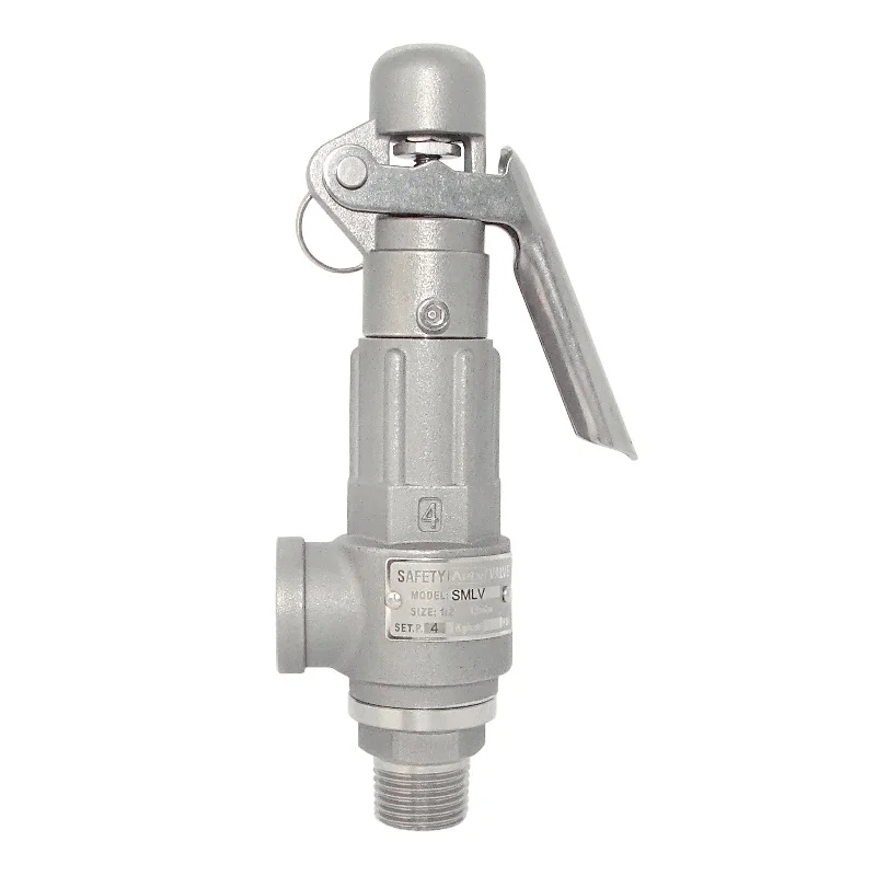
◎With sanitary design and completely material of stainless steel, the valves is the best choice for protection of equipments in diary, food, beverage, pharmaceutical and fine chemical industries.
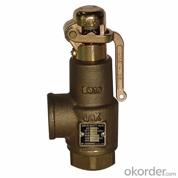
Manual fast row safety valve features: you can open the valve manually, the spot cleaning (used together with the pump channel) can allow the fluid to pass through
◎When the pressure in the pipes is exceed the specific pressure, the valve will open automatically to make the liquid pass over,so that pressure in the pipeline is reduced.
Because of different of drive source, SSV can dividedinto Hydraulic safety valve and pneumatic valve ; With thermal and high voltage explosion-proof device ; Actuators and prepare two parts of the valve, standard interface, easy replacement and maintenance .
This valve is used for power plant boilers, pressure containers, pressure and temperature reducing device and other facilities. It serves to prevent the pressure exceeding the highest allowable pres-sure value and ensure the safety of the device when working.
(1)The pressure of the disc is balanced through the lever and heavy hammer and the valve is ensured seal by moving the for ton of heavy hammer and changing the weight of heavy hammer to reach the required set pressure.
(3)At the top of valve is equipped an electromagnet to open and another to close the valve. The actions of the mechanism and the electric appliance are separate and will not affect each other.
(2)Impulse safety valve shall be installed vertically and the lever shall be kept level. The clearance from the lever to both sides of guide fork shall be even.
(4)A long distance between the leading pipe of the impulse safety valve and the inlet pipe of the main safety valve shall be kept. And the distance between the electric contact pressure meter and the inlet pipe of the main safety valve shall be no less than 5 times of the diameter of the inlet pipe, for feat that the validity of the mater and the impulse safety valve may be affected by the steam releasing process of the main safety valve.
This valve is used for power plant boilers, pressure containers, pressure and temperature reducing device and other facilities. It serves to present the pressure exceeding the highest allowable pres-sure value and ensure the safety of the device when working.
1,When the medium pressure rises to the set pressure, the in-pulse safety valve opens, and the medium in the impulse pipe enters into the piston chamber of the main safety valve from impulse pipe, forcing the piston to descend, and then the valve automatically open-s; when the impulse safety valve closes, the disc will slash automatically close.
2,The main safety valve shall be fastened upon the gallows, which sustains the back-seat force produced in the steam discharging process of the main safety valve.
3,The exhaust pipe shall contain a special gallows to prevent the force of its weight directly applying on the main safety valve. The connecting Lange At the lowest point of the exhaust pipe, water drainage shall be taken into consideration to avoid producing water hammer while discharging set between the main safety valve and exhaust pipe shall eliminate any extra stress.

Feature: 1.Prime,High Quality 2.Standards:NPT,BSP,ISO,DIN 3.Material:ss304,316,316L 4.Certificates:ISO9001:2008, CE 5.Brand Name: FD-LOK 6.Place of Origin: Zhejiang, China (Mainland) Details: 1.Set pressures:50 to 6000 psig @ 70°F ( 0.34 to 41.4 Mpa @ 21°C ) 2.Maximum outlet pressure:1500 psig ( 103 bar ) 3.Working temperatures: -10°F to 300°F ( -23°C to 148°C ) 4.Many options for various end connections 5.Liquid or gas service 6.Adjustable bonnet cap,and adjustable set pressure 7.Balance stem design to eliminate the effect of system back pressure 8. 7 color-coded springs avaliable for a wide range of set pressure 9.Lock wired secure cap to maintain set pressure 10.Many options for various seal materials 11.Label identifies the set pressure range 12.Manual override handle available to open the valve without changing the set pressure when lower than 1500 psig Our product is high quality,ensure safe,trouble-free performance. Our Capacity: 1)Date of foundation:2002 2)Annual Revenue:Above $9 million 3)About QC: Excellence, quality first is our philosophy 4)Sales Market: Europe,North America,Southeast Asia and Brazil 5)Main Products: Compression Tube Fittings,Pipe Fittings, Needle Valves, Instrument Ball Valves, 2&3&5 way Valve Manifolds, Check Vlaves, Gate Valves, Block&Bleed Valve, Sample Cylinders, Relief Valves, Syphons, Globe Valves, Plug Valves, Tube
As soon as mankind was able to boil water to create steam, the necessity of the safety device became evident. As long as 2000 years ago, the Chinese were using cauldrons with hinged lids to allow (relatively) safer production of steam. At the beginning of the 14th century, chemists used conical plugs and later, compressed springs to act as safety devices on pressurised vessels.
Early in the 19th century, boiler explosions on ships and locomotives frequently resulted from faulty safety devices, which led to the development of the first safety relief valves.
In 1848, Charles Retchie invented the accumulation chamber, which increases the compression surface within the safety valve allowing it to open rapidly within a narrow overpressure margin.
Today, most steam users are compelled by local health and safety regulations to ensure that their plant and processes incorporate safety devices and precautions, which ensure that dangerous conditions are prevented.
The principle type of device used to prevent overpressure in plant is the safety or safety relief valve. The safety valve operates by releasing a volume of fluid from within the plant when a predetermined maximum pressure is reached, thereby reducing the excess pressure in a safe manner. As the safety valve may be the only remaining device to prevent catastrophic failure under overpressure conditions, it is important that any such device is capable of operating at all times and under all possible conditions.
Safety valves should be installed wherever the maximum allowable working pressure (MAWP) of a system or pressure-containing vessel is likely to be exceeded. In steam systems, safety valves are typically used for boiler overpressure protection and other applications such as downstream of pressure reducing controls. Although their primary role is for safety, safety valves are also used in process operations to prevent product damage due to excess pressure. Pressure excess can be generated in a number of different situations, including:
The terms ‘safety valve’ and ‘safety relief valve’ are generic terms to describe many varieties of pressure relief devices that are designed to prevent excessive internal fluid pressure build-up. A wide range of different valves is available for many different applications and performance criteria.
In most national standards, specific definitions are given for the terms associated with safety and safety relief valves. There are several notable differences between the terminology used in the USA and Europe. One of the most important differences is that a valve referred to as a ‘safety valve’ in Europe is referred to as a ‘safety relief valve’ or ‘pressure relief valve’ in the USA. In addition, the term ‘safety valve’ in the USA generally refers specifically to the full-lift type of safety valve used in Europe.
Pressure relief valve- A spring-loaded pressure relief valve which is designed to open to relieve excess pressure and to reclose and prevent the further flow of fluid after normal conditions have been restored. It is characterised by a rapid-opening ‘pop’ action or by opening in a manner generally proportional to the increase in pressure over the opening pressure. It may be used for either compressible or incompressible fluids, depending on design, adjustment, or application.
Safety valves are primarily used with compressible gases and in particular for steam and air services. However, they can also be used for process type applications where they may be needed to protect the plant or to prevent spoilage of the product being processed.
Relief valve - A pressure relief device actuated by inlet static pressure having a gradual lift generally proportional to the increase in pressure over opening pressure.
Relief valves are commonly used in liquid systems, especially for lower capacities and thermal expansion duty. They can also be used on pumped systems as pressure overspill devices.
Safety relief valve - A pressure relief valve characterised by rapid opening or pop action, or by opening in proportion to the increase in pressure over the opening pressure, depending on the application, and which may be used either for liquid or compressible fluid.
In general, the safety relief valve will perform as a safety valve when used in a compressible gas system, but it will open in proportion to the overpressure when used in liquid systems, as would a relief valve.
Safety valve- A valve which automatically, without the assistance of any energy other than that of the fluid concerned, discharges a quantity of the fluid so as to prevent a predetermined safe pressure being exceeded, and which is designed to re-close and prevent further flow of fluid after normal pressure conditions of service have been restored.
Huibo is the most professional safety valve manufacturer and supplier in China. Our factory offers the best quality customized safety valve made in China with competitive price. Welcome to contact us for OEM service.
We"re well-known as one of the leading safety valve manufacturers and suppliers in China for our customized products and OEM service. Please feel free to buy quality safety valve made in China here from our factory.

There are various safety valves available to meet various applications and performance criteria demanded by various industries. Furthermore, national standards determine many types of varied safety valves.
Standard ASME I and ASME VIII standards for boiler applications and vessels and ASME / ANSI PTC 25.3 standards for safety valves and relief valves provide the following definition. These standards set performance characteristics and define various types of safety valves used:
ASME I valve - A safety relief valve conforming to the requirements of Section I of the ASME pressure vessel code for boiler applications which will open within 3% overpressure and close within 4%. It will usually feature two blowdown rings and is identified by a National Board ‘V’ stamp.
ASME VIII valve - A safety relief valve conforming to the requirements of Section VIII of the ASME pressure vessel code for pressure vessel applications which will open within 10% overpressure and close within 7%. Identified by a National Board ‘UV’ stamp.
Full bore safety valve - A safety valve having no protrusions in the bore, and wherein the valve lifts to an extent sufficient for the minimum area at any section, at or below the seat, to become the controlling orifice.
Conventional safety relief valve - The spring housing is vented to the discharge side, hence operational characteristics are directly affected by changes in the backpressure to the valve.
Balanced safety relief valve - A balanced valve incorporates a means of minimizing the effect of backpressure on the operational characteristics of the valve.
Pilot operated pressure relief valve - The major relieving device is combined with, and is controlled by, a self-actuated auxiliary pressure relief device.
Power-actuated safety relief valve - A pressure relief valve in which the major pressure-relieving device is combined with, and controlled by, a device requiring an external source of energy.
Standard safety valve - A valve which, following the opening, reaches the degree of lift necessary for the mass flowrate to be discharged within a pressure rise of not more than 10%. (The valve is characterized by a pop-type action and is sometimes known as high lift).
Full lift (Vollhub) safety valve - A safety valve which, after commencement of lift, opens rapidly within a 5% pressure rise up to the full lift as limited by the design. The amount of lift up to the rapid opening (proportional range) shall not be more than 20%.
Directly loaded safety valve - A safety valve in which the opening force underneath the valve disc is opposed by a closing force such as a spring or a weight.
Proportional safety valve - A safety valve that opens more or less steadily in relation to the increase in pressure. Sudden opening within a 10% lift range will not occur without a pressure increase. Following opening within a pressure of not more than 10%, these safety valves achieve the lift necessary for the mass flow to be discharged.
Diaphragm safety valve - A directly loaded safety valve wherein linear moving and rotating elements and springs are protected against the effects of the fluid by a diaphragm
Bellows safety valve - A directly loaded safety valve wherein sliding and (partially or fully) rotating elements and springs are protected against the effects of the fluids by a bellows. The bellows may be of such a design that it compensates for influences of backpressure.
Controlled safety valve- Consists of the main valve and a control device. It also includes direct acting safety valves with supplementary loading in which, until the set pressure is reached, an additional force increases the closing force.
Safety valve - A safety valve which automatically, without the assistance of any energy other than that of the fluid concerned, discharges a quantity of the fluid so as to prevent a predetermined safe pressure from being exceeded, and which is designed to re-close and prevent further flow of fluid after normal pressure conditions of service have been restored. Note; the valve can be characterized either by pop action (rapid opening) or by opening in proportion (not necessarily linear) to the increase in pressure over the set pressure.
Directly loaded safety valve - A safety valve in which the loading due to the fluid pressure underneath the valve disc is opposed only by a direct mechanical loading device such as weight, lever, and weight, or a spring.
Assisted safety valve - A safety valve which by means of a powered assistance mechanism, may additionally be lifted at a pressure lower than the set pressure and will, even in the event of a failure of the assistance mechanism, comply with all the requirements for safety valves given in the standard.
Supplementary loaded safety valve - A safety valve that has, until the pressure at the inlet to the safety valve reaches the set pressure, an additional force, which increases the sealing force.
Notes; This additional strength (additional burden), which can be provided through foreign resources, is reliably released when the pressure on the safety valve inlet reaches the specified pressure. The amount of additional loading is very regulated that if the additional loading is not released, the safety valve will reach its certified discharge capacity at a pressure which is no greater than 1.1 times the maximum pressure that is permitted to be protected.
Pilot operated safety valve - A safety valve, the operation of which is initiated and controlled by the fluid discharged from a pilot valve, which is itself, a directly loaded safety valve subject to the requirement of the standard.
The common characteristic shared between the definitions of conventional safety valves in the different standards, is that their operational characteristics are affected by any backpressure in the discharge system. It is important to note that the total backpressure is generated from two components; superimposed backpressure and the built-up backpressure:
Subsequently, in a conventional safety valve, only the superimposed backpressure will affect the opening characteristic and set value, but the combined backpressure will alter the blowdown characteristic and re-seat value.
Once the valve starts to open, the effects of built-up backpressure also have to be taken into account. For a conventional safety valve with the spring housing vented to the discharge side of the valve.
Therefore, if the back pressure is greater than the overpressure, the valve will tend to close, reducing the flow. This can lead to instability within the system and can result in flutter or chatter of the valve.
In general, if conventional safety valves are used in applications, where there is excessive built-up backpressure, they will not perform as expected. According to the API 520 Recommended Practice Guidelines:
A conventional pressure relief valve should typically not be used when the built-up backpressure is greater than 10% of the set pressure at 10% overpressure. A higher maximum allowable built-up backpressure may be used for overpressure greater than 10%.
The European Standard EN ISO 4126, however, states that the built-up backpressure should be limited to 10% of the set pressure when the valve is discharging at the certified capacity.
For the majority of steam applications, the back pressure can be maintained within these limits by carefully sizing any discharge pipes. This will be discussed in Module 9.4. If, however, it is not feasible to reduce the backpressure, then it may be necessary to use a balanced safety valve.
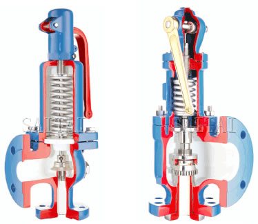
Balanced safety valves are those that incorporate a means of eliminating the effects of backpressure. There are two basic designs that can be used to achieve this:
The bellows arrangement prevents back pressure acting on the upper side of the disc within the area of the bellows. The disc area extending beyond the bellows and the opposing disc area are equal, and so the forces acting on the disc are balanced, and the backpressure has little effect on the valve opening pressure.
Bellows failure is an important concern when using a bellows balanced safety valve, as this may affect the set pressure and capacity of the valve. It is important, therefore, that there is some mechanism for detecting any uncharacteristic fluid flow through the bellows vents. In addition, some bellows balanced safety valves include an auxiliary piston that is used to overcome the effects of backpressure in the case of bellows failure. This type of safety valve is usually only used on critical applications in the oil and petrochemical industries.
In addition to reducing the effects of backpressure, the bellows also serve to isolate the spindle guide and the spring from the process fluid, this is important when the fluid is corrosive.
Since balanced pressure relief valves are typically more expensive than their unbalanced counterparts, they are commonly only used where high-pressure manifolds are unavoidable, or in critical applications where a very precise set pressure or blowdown is required.
This type of safety valve uses the flowing medium itself, through a pilot valve, to apply the closing force on the safety valve disc. The pilot valve is itself a small safety valve.
The diaphragm type is typically only available for low-pressure applications and it produces a proportional type action, characteristic of relief valves used in liquid systems. They are therefore of little use in steam systems, consequently, they will not be considered in this text.
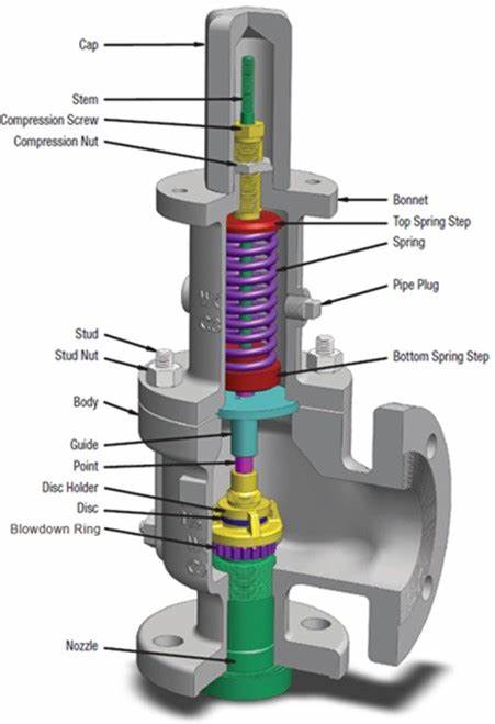
The piston-type valve consists of the main valve, which uses a piston-shaped closing device (or obturator), and an external pilot valve. Below photo shows a diagram of a typical piston type, pilot-operated safety valve.
The piston and seating arrangement incorporated in the main valve is designed so that the bottom area of the piston, exposed to the inlet fluid, is less than the area of the top of the piston. As both ends of the piston are exposed to the fluid at the same pressure, this means that under normal system operating conditions, the closing force, resulting from the larger top area, is greater than the inlet force. The resultant downward force therefore holds the piston firmly on its seat.
If the inlet pressure were to rise, the net closing force on the piston also increases, ensuring that a tight shut-off is continually maintained. However, when the inlet pressure reaches the set pressure, the pilot valve will pop open to release the fluid pressure above the piston. With much less fluid pressure acting on the upper surface of the piston, the inlet pressure generates a net upwards force and the piston will leave its seat. This causes the main valve to pop open, allowing the process fluid to be discharged.
When the inlet pressure has been sufficiently reduced, the pilot valve will reclose, preventing the further release of fluid from the top of the piston, thereby re-establishing the net downward force, and causing the piston to reseat.
Pilot operated safety valves offer good overpressure and blowdown performance (a blowdown of 2% is attainable). For this reason, they are used where a narrow margin is required between the set pressure and the system operating pressure. Pilot operated valves are also available in much larger sizes, making them the preferred type of safety valve for larger capacities.
One of the main concerns with pilot operated safety valves is that the small bore, pilot connecting pipes are susceptible to blockage by foreign matter, or due to the collection of condensate in these pipes. This can lead to the failure of the valve, either in the open or closed position, depending on where the blockage occurs.
The terms full lift, high lift and low lift refer to the amount of travel the disc undergoes as it moves from its closed position to the position required to produce the certified discharge capacity, and how this affects the discharge capacity of the valve.
A full lift safety valve is one in which the disc lifts sufficiently, so that the curtain area no longer influences the discharge area. The discharge area, and therefore the capacity of the valve are subsequently determined by the bore area. This occurs when the disc lifts a distance of at least a quarter of the bore diameter. A full lift conventional safety valve is often the best choice for general steam applications.
The disc of a high lift safety valve lifts a distance of at least 1/12th of the bore diameter. This means that the curtain area, and ultimately the position of the disc, determines the discharge area. The discharge capacities of high lift valves tend to be significantly lower than those of full lift valves, and for a given discharge capacity, it is usually possible to select a full lift valve that has a nominal size several times smaller than a corresponding high lift valve, which usually incurs cost advantages.Furthermore, high lift valves tend to be used on compressible fluids where their action is more proportional.
In low lift valves, the disc only lifts a distance of 1/24th of the bore diameter. The discharge area is determined entirely by the position of the disc, and since the disc only lifts a small amount, the capacities tend to be much lower than those of full or high lift valves.
Except when safety valves are discharging, the only parts that are wetted by the process fluid are the inlet tract (nozzle) and the disc. Since safety valves operate infrequently under normal conditions, all other components can be manufactured from standard materials for most applications. There are however several exceptions, in which case, special materials have to be used, these include:
Cast steel - Commonly used on higher pressure valves (up to 40 bar g). Process type valves are usually made from a cast steel body with an austenitic full nozzle type construction.
For all safety valves, it is important that moving parts, particularly the spindle and guides are made from materials that will not easily degrade or corrode. As seats and discs are constantly in contact with the process fluid, they must be able to resist the effects of erosion and corrosion.
The spring is a critical element of the safety valve and must provide reliable performance within the required parameters. Standard safety valves will typically use carbon steel for moderate temperatures. Tungsten steel is used for higher temperature, non-corrosive applications, and stainless steel is used for corrosive or clean steam duty. For sour gas and high temperature applications, often special materials such as monel, hastelloy and ‘inconel’ are used.
A key option is the type of seating material used. Metal-to-metal seats, commonly made from stainless steel, are normally used for high temperature applications such as steam. Alternatively, resilient discs can be fixed to either or both of the seating surfaces where tighter shut-off is required, typically for gas or liquid applications. These inserts can be made from a number of different materials, but Viton, nitrile or EPDM are the most common. Soft seal inserts are not generally recommended for steam use.
Standard safety valves are generally fitted with an easing lever, which enables the valve to be lifted manually in order to ensure that it is operational at pressures in excess of 75% of set pressure. This is usually done as part of routine safety checks, or during maintenance to prevent seizing. The fitting of a lever is usually a requirement of national standards and insurance companies for steam and hot water applications. For example, the ASME Boiler and Pressure Vessel Code states that pressure relief valves must be fitted with a lever if they are to be used on air, water over 60°C, and steam.
A standard or open lever is the simplest type of lever available. It is typically used on applications where a small amount of leakage of the fluid to the atmosphere is acceptable, such as on steam and air systems, (see Figure 9.2.5 (a)).
Where it is not acceptable for the media to escape, a packed lever must be used. This uses a packed gland seal to ensure that the fluid is contained within the cap, (see Figure 9.2.5 (b)).
For service where a lever is not required, a cap can be used to simply protect the adjustment screw. If used in conjunction with a gasket, it can be used to prevent emissions to the atmosphere, (see Figure 9.2.6).
A test gag (Figure 9.2.7) may be used to prevent the valve from opening at the set pressure during hydraulic testing when commissioning a system. Once tested, the gag screw is removed and replaced with a short blanking plug before the valve is placed in service.
The amount of fluid depends on the particular design of the safety valve. If the emission of this fluid into the atmosphere is acceptable, the spring housing may be vented to the atmosphere – an open bonnet. This is usually advantageous when the safety valve is used on high-temperature fluids or for boiler applications as, otherwise, high temperatures can relax the spring, altering the set pressure of the valve. However, using an open bonnet exposes the valve spring and internals to environmental conditions, which can lead to damage and corrosion of the spring.
When the fluid must be completely contained by the safety valve (and the discharge system), it is necessary to use a closed bonnet, which is not vented to the atmosphere. This type of spring enclosure is almost universally used for small screwed valves and, it is becoming increasingly common on many valve ranges since, particularly on steam, discharge of the fluid could be hazardous to personnel.
Some safety valves, most commonly those used for water applications, incorporate a flexible diaphragm or bellows to isolate the safety valve spring and upper chamber from the process fluid, (see Figure 9.2.9).
An elastomer bellows or diaphragm is commonly used in hot water or heating applications, whereas a stainless steel one would be used on process applications employing hazardous fluids.

Solenoid directional valves and cartridges with inductive sensors to monitor the spool/poppet position, certified to Machine Directive 2006/42/EC. Pressure relief valves certified to PED 2014/68/EU.

Valves for industrial applicationsIn order to prevent the uncontrolled rise in pressure in pressure vessels or pressurized pipelines, a safety valve is inserted. The safety valve is designed so that it opens at a given maximum pressure, thereby relieving the line or the container. Safety valves find their use in almost all areas of the pressure vessel and pipeline construction. In cryogenics as a spring-loaded safety valve for example.

Pressure relief valves (safety relief valves) are designed to open at a preset pressure and discharge fluid until pressure drops to acceptable levels. The development of the safety relief valve has an interesting history.
Denis Papin is credited by many sources as the originator of the first pressure relief valve (circa 1679) to prevent overpressure of his steam powered “digester”. His pressure relief design consisted of a weight suspended on a lever arm. When the force of the steam pressure acting on the valve exceeded the force of the weight acting through the lever arm the valve opened. Designs requiring a higher relief pressure setting required a longer lever arm and/or larger weights. This simple system worked however more space was needed and it coud be easily tampered with leading to a possible overpressure and explosion. Another disadvantage was premature opening of the valve if the device was subjected to bouncing movement.
Direct-acting deadweight pressure relief valves: Later to avoid the disadvantages of the lever arrangement, direct-acting deadweight pressure relief valves were installed on early steam locomotives. In this design, weights were applied directly to the top of the valve mechanism. To keep the size of the weights in a reasonable range, the valve size was often undersized resulting in a smaller vent opening than required. Often an explosion would occur as the steam pressure rose faster than the vent could release excess pressure. Bouncing movements also prematurely released pressure.
Direct acting spring valves: Timothy Hackworth is believed to be the first to use direct acting spring valves (circa 1828) on his locomotive engine called the Royal George. Timothy utilized an accordion arrangement of leaf springs, which would later be replaced with coil springs, to apply force to the valve. The spring force could be fine tuned by adjusting the nuts retaining the leaf springs.
Refinements to the direct acting spring relief valve design continued in subsequent years in response to the widespread use of steam boilers to provide heat and to power locomotives, river boats, and pumps. Steam boilers are less common today but the safety relief valve continues to be a critical component, in systems with pressure vessels, to protect against damage or catastrophic failure.
Each application has its own unique requirements but before we get into the selection process, let’s have a look at the operating principles of a typical direct acting pressure relief valve.
In operation, the pressure relief valve remains normally closed until pressures upstream reaches the desired set pressure. The valve will crack open when the set pressure is reached, and continue to open further, allowing more flow as over pressure increases. When upstream pressure falls a few psi below the set pressure, the valve will close again.
Most commonly, pressure relief valves employ a spring loaded “poppet” valve as a valve element. The poppet includes an elastomeric seal or, in some high pressure designs a thermoplastic seal, which is configured to make a seal on a valve seat. In operation, the spring and upstream pressure apply opposing forces on the valve. When the force of the upstream pressure exerts a greater force than the spring force, then the poppet moves away from the valve seat which allows fluid to pass through the outlet port. As the upstream pressure drops below the set point the valve then closes.
Piston style designs are often used when higher relief pressures are required, when ruggedness is a concern or when the relief pressure does not have to be held to a tight tolerance. Piston designs tend to be more sluggish, compared to diaphragm designs due to friction from the piston seal. In low pressure applications, or when high accuracy is required, the diaphragm style is preferred. Diaphragm relief valves employ a thin disc shaped element which is used to sense pressure changes. They are usually made of an elastomer, however, thin convoluted metal is used in special applications. Diaphragms essentially eliminate the friction inherent with piston style designs. Additionally, for a particular relief valve size, it is often possible to provide a greater sensing area with a diaphragm design than would be feasible with a piston style design.
The reference force element is usually a mechanical spring. This spring exerts a force on the sensing element and acts to close the valve. Many pressure relief valves are designed with an adjustment which allows the user to adjust the relief pressure set-point by changing the force exerted by the reference spring.
What is the maximum flow rate that the application requires? How much does the flow rate vary? Porting configuration and effective orifices are also important considerations.
The chemical properties of the fluid should be considered before determining the best materials for your application. Each fluid will have its own unique characteristics so care must be taken to select the appropriate body and seal materials that will come in contact with the fluid. The parts of the pressure relief valve in contact with the fluid are known as the “wetted” components. If the fluid is flammable or hazardous in nature the pressure relief valve must be capable of discharging it safely.
In many high technology applications space is limited and weight is a factor. Some manufactures specialize in miniature components and should be consulted. Material selection, particularly the relief valve body components, will impact weight. Also carefully consider the port (thread) sizes, adjustment styles, and mounting options as these will influence size and weight.
In many high technology applications space is limited and weight is a factor. Some manufactures specialize in miniature components and should be consulted. Material selection, particularly the relief valve body components, will impact weight. Also carefully consider the port (thread) sizes, adjustment styles, and mounting options as these will influence size and weight.
A wide range of materials are available to handle various fluids and operating environments. Common pressure relief valve component materials include brass, plastic, and aluminum. Various grades of stainless steel (such as 303, 304, and 316) are available too. Springs used inside the relief valve are typically made of music wire (carbon steel) or stainless steel.
Brass is suited to most common applications and is usually economical. Aluminum is often specified when weight is a consideration. Plastic is considered when low cost is of primarily concern or a throw away item is required. Stainless Steels are often chosen for use with corrosive fluids, when cleanliness of the fluid is a consideration or when the operating temperatures will be high.
Equally important is the compatibility of the seal material with the fluid and with the operating temperature range. Buna-N is a typical seal material. Optional seals are offered by some manufacturers and these include: Fluorocarbon, EPDM, Silicone, and Perfluoroelastomer.
The materials selected for the pressure relief valve not only need to be compatible with the fluid but also must be able to function properly at the expected operating temperature. The primary concern is whether or not the elastomer chosen will function properly throughout the expected temperature range. Additionally, the operating temperature may affect flow capacity and/or the spring rate in extreme applications.
Beswick Engineering manufactures four styles of pressure relief valves to best suit your application. The RVD and RVD8 are diaphragm based pressure relief valves which are suited to lower relief pressures. The RV2 and BPR valves are piston based designs.

Pressure Relief Valves are designed to protect chemical feed systems from over pressure damage caused by defective equipment or a blockage in the chemical feed line. Robust construction ensures reliability in the rigorous service of municipal and industrial applications. When the preset pressure is exceeded the diaphragm is forced up and the chemical flows out the relief port, back to the chemical tank or to the suction side of the pump. The valves are preset at 50 psi, however they are field adjustable from 10-150 psi, via the adjustment screw. The relief valve should be set approximately 15 psi higher than the system pressure with installation made as close as possible to the pump without any valves or accessories between the pressure relief valve and the pump.Reliable


 8613371530291