
how to set safety valve pressure quotation

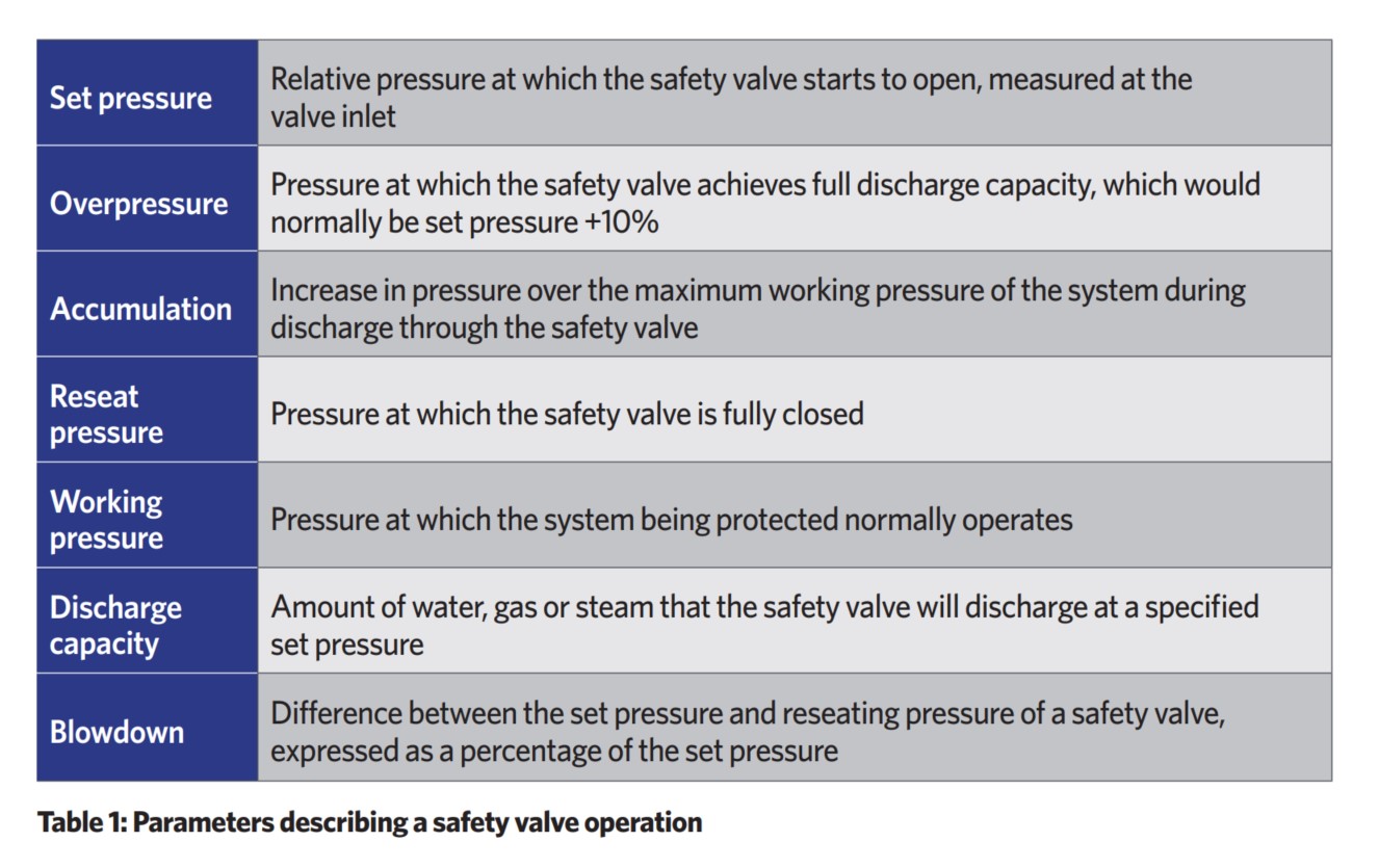
The principal type of device used to prevent overpressure in plants is the safety or safety relief valve. The safety valve operates by releasing a volume of fluid from within the plant when a predetermined maximum pressure is reached, thereby reducing the excess pressure in a safe manner.
1. Before the safety valve leaves the factory, we should adjust its opening pressure to reach the set value user specifies. If a user specifies the working pressure level of the spring, then we should adjust it according to the lower limit of the pressure level.
2. Before the safety valve is installed on the protected equipment, users must re-adjust it at the installation site to ensure the set pressure value of the safety valve meets the requirements.
3. In the range of the working pressure level of the spring specified by the nameplate, by turning the adjustment stem to change the compression amount of the spring, we can adjust the opening pressure.
5. To ensure the accuracy of opening pressure value, make sure the medium conditions, such as medium types and temperatures, are as close as possible to the actual operating conditions. When the medium type changes, especially when the dielectric aggregation is different (for example, from the liquid phase to the gas phase), the opening pressure often changes. When the operating temperature rises, the opening pressure is generally reduced. When it’s adjusted at room temperature and used for high temperature, the set pressure value at room temperature should be slightly higher than the required opening pressure value. How high the temperature should be has something to do with the valve structure and material selection, so it should be based on the manufacturer’s instructions.
6. The conventional safety valve is used to fix the additional backpressure. When adjusting opening pressure after the testing (at this time, the backpressure is atmospheric pressure), the set value should be required opening pressure minus additional backpressure.
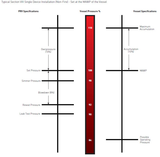
By adding the 0.1 bar shut-off margin, the safety valve set pressure has to be 10% greater than 6.4 bar. For this example, this means that the safety valve’s set pressure has to be: The set pressure would therefore be chosen as 7.11 bar, provided that this does not exceed the MAWP of the protected system.
Thank you for reading our article and we hope it can help you better understand the adjustment of the opening pressure of the safety valve. If you want to learn more about safety valves, we would like to advise you to visit Adamant Valve homepage for more information.

In order to ensure that the maximum allowable accumulation pressure of any system or apparatus protected by a safety valve is never exceeded, careful consideration of the safety valve’s position in the system has to be made. As there is such a wide range of applications, there is no absolute rule as to where the valve should be positioned and therefore, every application needs to be treated separately.
A common steam application for a safety valve is to protect process equipment supplied from a pressure reducing station. Two possible arrangements are shown in Figure 9.3.3.
The safety valve can be fitted within the pressure reducing station itself, that is, before the downstream stop valve, as in Figure 9.3.3 (a), or further downstream, nearer the apparatus as in Figure 9.3.3 (b). Fitting the safety valve before the downstream stop valve has the following advantages:
• The safety valve can be tested in-line by shutting down the downstream stop valve without the chance of downstream apparatus being over pressurised, should the safety valve fail under test.
• When setting the PRV under no-load conditions, the operation of the safety valve can be observed, as this condition is most likely to cause ‘simmer’. If this should occur, the PRV pressure can be adjusted to below the safety valve reseat pressure.
Indeed, a separate safety valve may have to be fitted on the inlet to each downstream piece of apparatus, when the PRV supplies several such pieces of apparatus.
• If supplying one piece of apparatus, which has a MAWP pressure less than the PRV supply pressure, the apparatus must be fitted with a safety valve, preferably close-coupled to its steam inlet connection.
• If a PRV is supplying more than one apparatus and the MAWP of any item is less than the PRV supply pressure, either the PRV station must be fitted with a safety valve set at the lowest possible MAWP of the connected apparatus, or each item of affected apparatus must be fitted with a safety valve.
• The safety valve must be located so that the pressure cannot accumulate in the apparatus viaanother route, for example, from a separate steam line or a bypass line.
It could be argued that every installation deserves special consideration when it comes to safety, but the following applications and situations are a little unusual and worth considering:
• Fire - Any pressure vessel should be protected from overpressure in the event of fire. Although a safety valve mounted for operational protection may also offer protection under fire conditions,such cases require special consideration, which is beyond the scope of this text.
• Exothermic applications - These must be fitted with a safety valve close-coupled to the apparatus steam inlet or the body direct. No alternative applies.
• Safety valves used as warning devices - Sometimes, safety valves are fitted to systems as warning devices. They are not required to relieve fault loads but to warn of pressures increasing above normal working pressures for operational reasons only. In these instances, safety valves are set at the warning pressure and only need to be of minimum size. If there is any danger of systems fitted with such a safety valve exceeding their maximum allowable working pressure, they must be protected by additional safety valves in the usual way.
In order to illustrate the importance of the positioning of a safety valve, consider an automatic pump trap (see Block 14) used to remove condensate from a heating vessel. The automatic pump trap (APT), incorporates a mechanical type pump, which uses the motive force of steam to pump the condensate through the return system. The position of the safety valve will depend on the MAWP of the APT and its required motive inlet pressure.
This arrangement is suitable if the pump-trap motive pressure is less than 1.6 bar g (safety valve set pressure of 2 bar g less 0.3 bar blowdown and a 0.1 bar shut-off margin). Since the MAWP of both the APT and the vessel are greater than the safety valve set pressure, a single safety valve would provide suitable protection for the system.
However, if the pump-trap motive pressure had to be greater than 1.6 bar g, the APT supply would have to be taken from the high pressure side of the PRV, and reduced to a more appropriate pressure, but still less than the 4.5 bar g MAWP of the APT. The arrangement shown in Figure 9.3.5 would be suitable in this situation.
Here, two separate PRV stations are used each with its own safety valve. If the APT internals failed and steam at 4 bar g passed through the APT and into the vessel, safety valve ‘A’ would relieve this pressure and protect the vessel. Safety valve ‘B’ would not lift as the pressure in the APT is still acceptable and below its set pressure.
It should be noted that safety valve ‘A’ is positioned on the downstream side of the temperature control valve; this is done for both safety and operational reasons:
Operation - There is less chance of safety valve ‘A’ simmering during operation in this position,as the pressure is typically lower after the control valve than before it.
Also, note that if the MAWP of the pump-trap were greater than the pressure upstream of PRV ‘A’, it would be permissible to omit safety valve ‘B’ from the system, but safety valve ‘A’ must be sized to take into account the total fault flow through PRV ‘B’ as well as through PRV ‘A’.
A pharmaceutical factory has twelve jacketed pans on the same production floor, all rated with the same MAWP. Where would the safety valve be positioned?
One solution would be to install a safety valve on the inlet to each pan (Figure 9.3.6). In this instance, each safety valve would have to be sized to pass the entire load, in case the PRV failed open whilst the other eleven pans were shut down.
If additional apparatus with a lower MAWP than the pans (for example, a shell and tube heat exchanger) were to be included in the system, it would be necessary to fit an additional safety valve. This safety valve would be set to an appropriate lower set pressure and sized to pass the fault flow through the temperature control valve (see Figure 9.3.8).

Safety is of the utmost importance when dealing with pressure relief valves. The valve is designed to limit system pressure, and it is critical that they remain in working order to prevent an explosion. Explosions have caused far too much damage in companies over the years, and though pressurized tanks and vessels are equipped with pressure relief vales to enhance safety, they can fail and result in disaster.
That’s also why knowing the correct way to test the valves is important. Ongoing maintenance and periodic testing of pressurized tanks and vessels and their pressure relief valves keeps them in working order and keep employees and their work environments safe. Pressure relief valves must be in good condition in order to automatically lower tank and vessel pressure; working valves open slowly when the pressure gets high enough to exceed the pressure threshold and then closes slowly until the unit reaches the low, safe threshold. To ensure the pressure relief valve is in good working condition, employees must follow best practices for testing them including:
If you consider testing pressure relief valves a maintenance task, you’ll be more likely to carry out regular testing and ensure the safety of your organization and the longevity of your
It’s important to note, however, that the American Society of Mechanical Engineers (ASME) and National Board Inspection Code (NBIC), as well as state and local jurisdictions, may set requirements for testing frequency. Companies are responsible for checking with these organizations to become familiar with the testing requirements. Consider the following NBIC recommendations on the frequency for testing relief valves:
High-pressure steam boilers greater than 15 psi and less than 400 psi – perform manual check every six months and pressure test annually to verify nameplate set pressure
High-pressure steam boilers 400 psi and greater – pressure test to verify nameplate set pressure every three years or as determined by operating experience as verified by testing history
High-temperature hot water boilers (greater than 160 psi and/or 250 degrees Fahrenheit) – pressure test annually to verify nameplate set pressure. For safety reasons, removal and testing on a test bench is recommended
When testing the pressure relief valve, raise and lower the test lever several times. The lever will come away from the brass stem and allow hot water to come out of the end of the drainpipe. The water should flow through the pipe, and then you should turn down the pressure to stop the leak, replace the lever, and then increase the pressure.
One of the most common problems you can address with regular testing is the buildup of mineral salt, rust, and corrosion. When buildup occurs, the valve will become non-operational; the result can be an explosion. Regular testing helps you discover these issues sooner so you can combat them and keep your boiler and valve functioning properly. If no water flows through the pipe, or if there is a trickle instead of a rush of water, look for debris that is preventing the valve from seating properly. You may be able to operate the test lever a few times to correct the issue. You will need to replace the valve if this test fails.
When testing relief valves, keep in mind that they have two basic functions. First, they will pop off when the pressure exceeds its safety threshold. The valve will pop off and open to exhaust the excess pressure until the tank’s pressure decreases to reach the set minimum pressure. After this blowdown process occurs, the valve should reset and automatically close. One important testing safety measure is to use a pressure indicator with a full-scale range higher than the pop-off pressure.
Thus, you need to be aware of the pop-off pressure point of whatever tank or vessel you test. You always should remain within the pressure limits of the test stand and ensure the test stand is assembled properly and proof pressure tested. Then, take steps to ensure the escaping pressure from the valve is directed away from the operator and that everyone involved in the test uses safety shields and wears safety eye protection.
After discharge – Because pressure relief valves are designed to open automatically to relieve pressure in your system and then close, they may be able to open and close multiple times during normal operation and testing. However, when a valve opens, debris may get into the valve seat and prevent the valve from closing properly. After discharge, check the valve for leakage. If the leakage exceeds the original settings, you need to repair the valve.
According to local jurisdictional requirements – Regulations are in place for various locations and industries that stipulate how long valves may operate before needing to be repair or replaced. State inspectors may require valves to be disassembled, inspected, repaired, and tested every five years, for instance. If you have smaller valves and applications, you can test the valve by lifting the test lever. However, you should do this approximately once a year. It’s important to note that ASME UG136A Section 3 requires valves to have a minimum of 75% operating pressure versus the set pressure of the valve for hand lifting to be performed for these types of tests.
Depending on their service and application– The service and application of a valve affect its lifespan. Valves used for clean service like steam typically last at least 20 years if they are not operated too close to the set point and are part of a preventive maintenance program. Conversely, valves used for services such as acid service, those that are operated too close to the set point, and those exposed to dirt or debris need to be replaced more often.
Pressure relief valves serve a critical role in protecting organizations and employees from explosions. Knowing how and when to test and repair or replace them is essential.
Boiler explosions have been responsible for widespread damage to companies throughout the years, and that’s why today’s boilers are equipped with safety valves and/or relief valves. Boiler safety valves are designed to prevent excess pressure, which is usually responsible for those devastating explosions. That said, to ensure that boiler safety valves are working properly and providing adequate protection, they must meet regulatory specifications and require ongoing maintenance and periodic testing. Without these precautions, malfunctioning safety valves may fail, resulting in potentially disastrous consequences.
Boiler safety valves are activated by upstream pressure. If the pressure exceeds a defined threshold, the valve activates and automatically releases pressure. Typically used for gas or vapor service, boiler safety valves pop fully open once a pressure threshold is reached and remain open until the boiler pressure reaches a pre-defined, safe lower pressure.
Boiler relief valves serve the same purpose – automatically lowering boiler pressure – but they function a bit differently than safety valves. A relief valve doesn’t open fully when pressure exceeds a defined threshold; instead, it opens gradually when the pressure threshold is exceeded and closes gradually until the lower, safe threshold is reached. Boiler relief valves are typically used for liquid service.
There are also devices known as “safety relief valves” which have the characteristics of both types discussed above. Safety relief valves can be used for either liquid or gas or vapor service.
Nameplates must be fastened securely and permanently to the safety valve and remain readable throughout the lifespan of the valve, so durability is key.
The National Board of Boiler and Pressure Vessel Inspectors offers guidance and recommendations on boiler and pressure vessel safety rules and regulations. However, most individual states set forth their own rules and regulations, and while they may be similar across states, it’s important to ensure that your boiler safety valves meet all state and local regulatory requirements.
The National Board published NB-131, Recommended Boiler and Pressure Vessel Safety Legislation, and NB-132, Recommended Administrative Boiler and Pressure Vessel Safety Rules and Regulationsin order to provide guidance and encourage the development of crucial safety laws in jurisdictions that currently have no laws in place for the “proper construction, installation, inspection, operation, maintenance, alterations, and repairs” necessary to protect workers and the public from dangerous boiler and pressure vessel explosions that may occur without these safeguards in place.
The documents are meant to be used as a guide for developing local laws and regulations and also may be used to update a jurisdiction’s existing requirements. As such, they’re intended to be modifiable to meet any jurisdiction’s local conditions.
The American Society of Mechanical Engineers (ASME) governs the code that establishes guidelines and requirements for safety valves. Note that it’s up to plant personnel to familiarize themselves with the requirements and understand which parts of the code apply to specific parts of the plant’s steam systems.
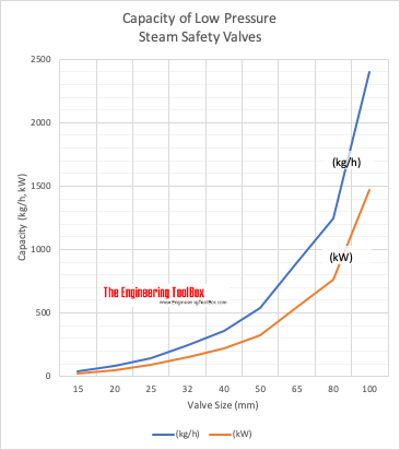
High steam capacity requirements, physical or economic constraints may make the use of a single safety valve impossible. In these cases, using multiple safety valves on the same system is considered an acceptable practice, provided that proper sizing and installation requirements are met – including an appropriately sized vent pipe that accounts for the total steam venting capacity of all valves when open at the same time.
The lowest rating (MAWP or maximum allowable working pressure) should always be used among all safety devices within a system, including boilers, pressure vessels, and equipment piping systems, to determine the safety valve set pressure.
General guidance on proper installation may seem like common sense to experienced installers and inspectors. A few of the most important guidelines and best practices include:
Avoid isolating safety valves from the system, such as by installing intervening shut-off valves located between the steam component or system and the inlet.
Contact the valve supplier immediately for any safety valve with a broken wire seal, as this indicates that the valve is unsafe for use. Safety valves are sealed and certified in order to prevent tampering that can prevent proper function.
Avoid attaching vent discharge piping directly to a safety valve, which may place unnecessary weight and additional stress on the valve, altering the set pressure.
This website is using a security service to protect itself from online attacks. The action you just performed triggered the security solution. There are several actions that could trigger this block including submitting a certain word or phrase, a SQL command or malformed data.
This website is using a security service to protect itself from online attacks. The action you just performed triggered the security solution. There are several actions that could trigger this block including submitting a certain word or phrase, a SQL command or malformed data.

Pressure valves regulatethe flow of gas through a pipeline by opening or closing in response to changes in the pressure of the gas, air, water, or steam flowing through the pipe. Pressure valves are commonly used on natural gas systems, propane systems, and other types of gas systems.
A pressure valve regulates the flow of gas through pipelines by opening or closing in accordance with changes in the pressure of gas flowing through the pipe, thereby maintaining a constant pressure within the pipeline.
Pressure valves work by using a spring-loaded diaphragm or electrical actuator to open or close the valve in the pipeline. As the pressure inside the pipeline rises, the diaphragm moves away from the valve seat, allowing more gas to pass through. Conversely, as the pressure falls, the diaphragms move toward the valve seat, restricting the flow of gas.
Testing a pressure valve should be done before installing it into a system. If there are leaks in the pipe, the valve will not work properly. To test a pressure valve, use a leak detector to check for leaks in the pipe. Then, turn off the main supply line and connect a gauge to the valve. Turn the valve on slowly until the pressure reaches the desired level. Once the pressure has reached the desired level, turn the valve off and wait for the pressure to drop back down to normal levels.
Pressure valve control is used in many applications, but they’re mainly found in all pneumatic and hydraulic systems. Pressure valve control has a wide range of functions that can be used to maintain a set pressure level in a part of a control loop or to keep system pressures below a desired limit.
There are many different types of pressure valve control in the industry, such as pressure relief valves, pressure reducing valves, pressure safety valves, counterbalance valves, unloading valves, and sequencing valves. Most of these pressure valves are typically closed valves, but pressure reducing valves are commonly open valves. It’s important for most of these valves to have restrictions so that the required pressure control can be achieved.
The flow must be consistent at all times in certain applications. Injuries or deaths can be caused by variations in the flow of gases. That’s why pressure control valves are so important in the processing loop.
Pressure relief valves are used to keep the pneumatic and hydraulic systems under the desired pressure value. Based on the different installation positions, pressure relief valves have different functions as below. The downstream pressure should be reduced to a constant level whenever it goes over a threshold.
A pressure relief valve is usually made of three parts: a ball/diaphragm, a spring-loaded mechanism, and a valve nozzle. A spring-loaded mechanism is placed in the valve’s housing, which is used to close the orifice. The pressure relief valve’s spring-loaded mechanism can be adjusted to change the pressure on the spring mechanism. If you want to increase the set pressure limit, just simply increase the pressure on the valve spring-load mechanism directly. If you want to decrease the set pressure limit, only decrease the pressure on the spring-load mechanism directly. A relief valve set-pressure can be specified by the manufacturer if there is no adjustability. When the set pressure is reached, the pressure overcomes the spring pressure and pushes the ball or diaphragm back opening the orifice and releasing the excess pressure. Depending on the media, it is either released into the atmosphere or discharged into it. It is possible to return to a tank or pumping circuit with compressed air.
There are two types of PRVs used in industry, one is the direct-acting pressure reducing valves, and the other type is pilot operated pressure reducing valves. The pressure reducing valves use globe type or angle type valve bodies. Most of the time, the main type of valve used in water systems is the direct acting valve, which consists of a globe-type body with a spring-loaded, heat-resistant diaphragm connected to the outlet of the valve that acts upon a spring. This spring holds a pre-set tension on the PRVs seat that’s installed with a pressure equalizing mechanism for precise water pressure control.
Pressure reducing valves are widely used in water conditions, such as in buildings, industrial plants, water treatment plants, homes, and so on. It will automatically reduce the water pressure from the main supply, in case to lower the water pressure to the destination and more sensible pressure for equipment.
Sequence valves are widely used in hydraulic systems, and are a type of pressure valve. Sequence valves are similar to pressure relief valves, but are used to control a set of pressure-related operating sequences. The main function of a sequence valve is to divert the flow in a predetermined sequence, and its construction is very similar to a pressure relief valve, which is a pressure actuated valve, usually a closed valve.
The sequence valve works on the principle that the valve plug will be moved when the main system pressure exceeds the spring setting. As a result, the outlet of the sequence valve will remain closed until the upstream pressure rises to a predetermined value, and then the valve will open, allowing air to transfer from the inlet to the outlet. Sequence valves are primarily used to force two actuators to operate in sequence. One nice feature of the sequence valve is that the valve has a separate drain connection to the spring chamber, under normal operating conditions, high pressures may occur at the output port. When the pressure rises above its limit, the pressure sequence valve will allow flow to occur in another part of the system. The pressure sequence valve is installed in a pneumatic control and its switching operation requires a specific pressure.
Counterbalance valves are used to handle loads that are over-limited and to safely suspend loads, these valves commonly work with hydraulic cylinders. This type of valve can also be used with hydraulic motors and is then commonly referred to as a brake valve. Both counterbalance valves and pilot-operated check valves can be used to lock the fluid in the cylinder to prevent drift. However, pilot-operated check valves cannot control over-running loads. A counterbalance valve should be used when uncontrolled motion may occur with an overrunning load.
The pressure safety valve is one of the most critical automatic safety devices in a pressure system, and in many cases is the last line of defense for safety. The important function of a pressure safety valve is overpressure protection, so ensure that the pressure safety valve can operate properly in any situation. Pressure safety valves are mainly used in pressurized vessels or equipment to protect the environment, property safety, and life safety in the event of an overpressure event. A pressure safety valve opens and releases excess pressure in a vessel or equipment, and closes again when normal conditions are restored and prevents the further release of fluid.
The Department of Labor does not endorse, takes no responsibility for, and exercises no control over the linked organization or its views, or contents, nor does it vouch for the accuracy or accessibility of the information contained on the destination server. The Department of Labor also cannot authorize the use of copyrighted materials contained in linked Web sites. Users must request such authorization from the sponsor of the linked Web site. Thank you for visiting our site. Please click the button below to continue.

Email us a photo of the part you need. We’ll ID it for you and get you a quote. If necessary, we will cross reference what you need with another manufacturer for a perfect substitution.
Our system monitors all inventory in our 100,000-sq. ft. warehouse. This technology allows our salespeople to give you real-time information on availability, price and delivery. No waiting. No factory delays.
Pressure relief valves are designed to protect equipment from overpressure. The valve should be handled with care, not subject to heavy shock loads, and protected to prevent dirt from getting inside. Failure to do so could result in property damage or serious injury to personnel.
Mount the valve in a vertical position so that the valve body is self-draining. If a body drain port is provided, make sure it is open when required by the ASME code. Do not plug any bonnet vent openings. The inlet piping should be as short as possible, with no elbows, and equal to or greater than the size of the pressure relief valve inlet connection. This will help limit the inlet pressure drop to 3% or less when the valve is relieving.
When discharge piping is connected to valve outlet, make sure it is self-draining when a body drain port is not used. The valve should not be connected to any discharge pipe that contains pressure before the valve opens or to any pipe where the pressure build-up is greater than 10% of the set pressure when the valve is open and relieving. Discharge piping other than a short tailpipe must be supported by something other than the valve. For steam service, a drip pan elbow or flexible connection between the valve and the pipe should be used to prevent excessive pipe stress, due to thermal expansion, from being imposed on the valve body.
For threaded valves, apply a small amount of pipe thread sealing compound to external threads only. Do not put any sealing compound on the first thread or any internal threads. To do so may cause the sealing compound to enter the valve and cause seat leakage. Use wrench flats provided to tighten the valve to the connecting pipe. Do not use the valve body or bonnet and do not over-tighten. To do so may cause valve leakage.
Maintain a system operating pressure at least 5 psig or 10% below the set pressure of the valve – whichever is greater. Operating too close to the valve set pressure will cause seat leakage and will shorten the time between valve maintenance.
Do not use the safety valve as a control valve to regulate system operating pressure. Excessive operation will cause the seat to leak and will require more frequent valve maintenance.
ASME Code-stamped valves equipped with lift levers are designed to be operated only when the system pressure is 75% of the set pressure or greater. When hand operating the valve, hold it open long enough to purge any foreign matter from the seat area. If a cable or wire is attached to the lift lever for remote actuation, make sure the direction of pull is the same as it would be if the lever were pulled directly by hand.
Maintenance should be performed on a regular basis. We recommend an initial inspection interval of 12 months. Depending on the service conditions and the condition of the valve, the suggested inspection interval may decrease or increase.
This website is using a security service to protect itself from online attacks. The action you just performed triggered the security solution. There are several actions that could trigger this block including submitting a certain word or phrase, a SQL command or malformed data.

Use these valves for emergency relief where pressures must be relieved quickly to reduce damage that could result from overpressure in a system. Where the overpressure needs to be controlled more gradually ,such as in back pressure or pump bypass applications use our
Although the valve is typically installed in the position illustrated, it can operate in any position or orientation, vertical horizontal, etc as long as it can be easily accessed for making adjustments.
These valves do not carry the Canadian CRN or ASME approval stamp and should not be applied where this requirement must be met. However, the valves generally meet or exceed ASME design criteria with wall thicknesses that are much heavier than the minimums required. For an additional charge, valves can be ordered with material certs and with a certified hydro-test certificate and other tests to meet special documentation and acceptance requirements.
Avoid locating the valve where freezing can occur, and if unavoidable, take precautions to insulate or heat wrap valve and piping to keep from freezing.

Acceptance: The quotation is for the purchase and sale of the products and/or services identified on the quotation and is our offer to the purchaser.The quotation will become a binding contract on the terms and conditions set forth herein when the purchaser places an order with us based upon the quotation, whether in writing or verbally, or accepts any shipment of the products and/or services. The quotation is not an acceptance or confirmation of any other terms. This quotation will be governed by these terms and conditions and in the event of any inconsistency between these terms and conditions and the purchaser"s order, these terms and conditions will prevail. Acceptance of the quotation must be made on its exact terms and conditions, and any additional or different terms and conditions proposed by the purchaser are hereby objected to and rejected unless otherwise stated.
Quotations and Orders: All quotations, purchase orders and sales contracts are subject to the following conditions of sale; (1) written sales quotations are void after (30) thirty days following the date of issuance; (2) typographical and clerical errors are subject to correction by us ; (3) all purchase orders are received subject to approval and acceptance at our corporate headquarters in Linden, New Jersey ; and (4) any assignment of this quotation or any right hereunder by the purchaser without our written consent will be null and void.
Shipment: All products and/or services covered by the quotation are sold F.O.B. either our plant in Linden, NJ or the manufacturer"s plant for the parts and/or valves required, unless otherwise indicated. The risk of loss or damage in transit will be upon the purchaser. The products will be prepared for shipment in a manner prescribed by us or the manufacturer and shipped by any public carrier which we deem satisfactory, unless the purchaser provides other specific shipping instructions when placing orders. Any date provided by us for completion of work or for shipment is intended as an estimate only and is not to be deemed a term of the quotation. Shipping charges shall be pre-paid and billed at the time of shipment.
Warranties and Limitations: We warrant only that our products will conform to their description herein and that at the time of sale our products will be free from defects on workmanship and material. The name and reputation of Certified Valve Repair stands prudently behind every valve or piece of equipment we recondition. We are valve repair specialists, if at any time, in any way, a valve or piece of equipment that we have repaired fails to provide complete satisfaction, please bring the matter to our attention. Every repaired valve, pump, instrument, or equipment when used in accordance with the manufacturer and our recommendations is guaranteed to be free from defective workmanship and material. We will repair or replace without charge, F.O.B. our plant any repaired unit which our own examination proves to be defective within a period stated by our firm at the time of delivery. We assume no responsibility for incidental damage or expense. Authorization is required before returned articles will be accepted.
Rejection: The purchaser"s claim of a right to reject allegedly incorrect or defective products must be submitted to us in writing within (10) ten days following receipt of such products. We will then have the option of inspecting such products at the purchaser"s plant or our own before allowing or rejecting the purchaser"s claim. Material may not be returned to us without first obtaining written permission in the form of (RGA) or Return Goods Authorization. All products returned to us must be shipped with transportation charges prepaid. Defects that do not impair satisfactory service cannot be the basis for rejection by the purchaser.
Cancellation: Acceptances and orders are not subject to cancellation, change, reduction in amount, suspension or deferral of delivery and/or services, except with our written consent and upon terms including cancellation charges, which fully indemnify and protect us against loss (including profits).
Taxes: Any sales, use/excise taxes and applicable state and local taxes, required to be collected by Certified shall be added to quoted prices and billed at time of invoicing, unless the purchaser provides us with a tax exemption certificate acceptable to the relevant taxing authorities.
Payment Terms: To a purchaser with a good credit rating, cash payment will be due within (30) days after the date of invoice. Invoices will be dated as of the date of shipment, or at our option the date services begin or are completed. Invoicing will commence biweekly or on completion of project, whichever comes first. We reserve the right to charge interest at the rate of 1.5% per month (18% per annum) on the balance of any overdue account. We also reserve the right to negotiate special payment terms on any order. In the event that at any time we have sound reason to question the purchaser"s ability or willingness to comply with the payment terms set forth herein, or in the event of the purchaser"s insolvency or bankruptcy, we may, in addition to our other rights under applicable law, (1) cancel any order outstanding and receive reimbursement for reasonable and proper cancellation charges, (2) require payment in advance or upon delivery, (3) defer late shipments, or (4) ship on any other terms satisfactory to us.
Indemnification: In the event the products and/or services described herein are used by the purchaser in a manner causing the infringement of any copyright, patent, trademark, registered design or similar proprietary right belonging to a third party, the purchaser will hold harmless and indemnify us as to any and all damages and costs for which we may become liable as a result of being charged with contributing to or inducing such infringement, provided that such infringements is not caused solely by the construction of said product or service provided without regard to the manner in which it is used.
Waivers and Remedies: Our failure to insist upon strict performance of any provision of the quotation or to take advantage of any of our rights hereunder shall not be construed as a waiver of any such provision or the relinquishment of any such right. Our rights and remedies hereunder shall be cumulative and in addition to every other right or remedy provided for herein or by law. If any provision of this quotation is found to be illegible or otherwise unenforceable by any court or other judicial or administrative body, the other provisions of the quotation shall not be affected thereby and will remain in full force and effect.
Actions: Any action for breach of the quotation, unless otherwise limited herein, must be brought to our attention within one year after the cause of action has a occurred.

This website is using a security service to protect itself from online attacks. The action you just performed triggered the security solution. There are several actions that could trigger this block including submitting a certain word or phrase, a SQL command or malformed data.
This relief valve can be used as a primary pressure control device or secondary (safety) pressure relief device. Many systems also use two relief valves, one set as the primary pressure control and the other set as a secondary relief. When used as a secondary pressure relief device, it is typically set approximately 200 PSI above the system pressure and provides additional protection for the pump and high-pressure system.
Blacoh engineers solved the problem of valve chatter with a better design. Most back pressure valves are based on a pressure relief design where the valve is normally closed. When a set pressure point is reached, the valve opens quickly with maximum flow to relieve pressure. This action doesn’t work well for back pressure valves that need to flow continuously to hold pressure upstream. When the valve opens quickly, pressure upstream drops rapidly and the valve slams closed. The sudden stop in flow causes a pressure spike that forces the valve open again. In a back pressure valve application, this cycle occurs many times per second, creating a loud, chattering valve with inferior performance and a shorter service life. Blacoh’s patented valves with flow stabilization technology meter flow when the valve opens to minimize the pressure drop that initiates this cycle. The result is a valve that doesn’t chatter, performs better and lasts longer.


 8613371530291