
improved high lift safety valve manufacturer
.jpg)
There is a wide range of safety valves available to meet the many different applications and performance criteria demanded by different industries. Furthermore, national standards define many varying types of safety valve.
The ASME standard I and ASME standard VIII for boiler and pressure vessel applications and the ASME/ANSI PTC 25.3 standard for safety valves and relief valves provide the following definition. These standards set performance characteristics as well as defining the different types of safety valves that are used:
ASME I valve - A safety relief valve conforming to the requirements of Section I of the ASME pressure vessel code for boiler applications which will open within 3% overpressure and close within 4%. It will usually feature two blowdown rings, and is identified by a National Board ‘V’ stamp.
ASME VIII valve- A safety relief valve conforming to the requirements of Section VIII of the ASME pressure vessel code for pressure vessel applications which will open within 10% overpressure and close within 7%. Identified by a National Board ‘UV’ stamp.
Full bore safety valve - A safety valve having no protrusions in the bore, and wherein the valve lifts to an extent sufficient for the minimum area at any section, at or below the seat, to become the controlling orifice.
Conventional safety relief valve -The spring housing is vented to the discharge side, hence operational characteristics are directly affected by changes in the backpressure to the valve.
Balanced safety relief valve -A balanced valve incorporates a means of minimising the effect of backpressure on the operational characteristics of the valve.
Pilot operated pressure relief valve -The major relieving device is combined with, and is controlled by, a self-actuated auxiliary pressure relief device.
Power-actuated safety relief valve - A pressure relief valve in which the major pressure relieving device is combined with, and controlled by, a device requiring an external source of energy.
Standard safety valve - A valve which, following opening, reaches the degree of lift necessary for the mass flowrate to be discharged within a pressure rise of not more than 10%. (The valve is characterised by a pop type action and is sometimes known as high lift).
Full lift (Vollhub) safety valve -A safety valve which, after commencement of lift, opens rapidly within a 5% pressure rise up to the full lift as limited by the design. The amount of lift up to the rapid opening (proportional range) shall not be more than 20%.
Direct loaded safety valve -A safety valve in which the opening force underneath the valve disc is opposed by a closing force such as a spring or a weight.
Proportional safety valve - A safety valve which opens more or less steadily in relation to the increase in pressure. Sudden opening within a 10% lift range will not occur without pressure increase. Following opening within a pressure of not more than 10%, these safety valves achieve the lift necessary for the mass flow to be discharged.
Diaphragm safety valve -A direct loaded safety valve wherein linear moving and rotating elements and springs are protected against the effects of the fluid by a diaphragm
Bellows safety valve - A direct loaded safety valve wherein sliding and (partially or fully) rotating elements and springs are protected against the effects of the fluids by a bellows. The bellows may be of such a design that it compensates for influences of backpressure.
Controlled safety valve - Consists of a main valve and a control device. It also includes direct acting safety valves with supplementary loading in which, until the set pressure is reached, an additional force increases the closing force.
Safety valve - A safety valve which automatically, without the assistance of any energy other than that of the fluid concerned, discharges a quantity of the fluid so as to prevent a predetermined safe pressure being exceeded, and which is designed to re-close and prevent further flow of fluid after normal pressure conditions of service have been restored. Note; the valve can be characterised either by pop action (rapid opening) or by opening in proportion (not necessarily linear) to the increase in pressure over the set pressure.
Direct loaded safety valve -A safety valve in which the loading due to the fluid pressure underneath the valve disc is opposed only by a direct mechanical loading device such as a weight, lever and weight, or a spring.
Assisted safety valve -A safety valve which by means of a powered assistance mechanism, may additionally be lifted at a pressure lower than the set pressure and will, even in the event of a failure of the assistance mechanism, comply with all the requirements for safety valves given in the standard.
Supplementary loaded safety valve - A safety valve that has, until the pressure at the inlet to the safety valve reaches the set pressure, an additional force, which increases the sealing force.
Note; this additional force (supplementary load), which may be provided by means of an extraneous power source, is reliably released when the pressure at the inlet of the safety valve reaches the set pressure. The amount of supplementary loading is so arranged that if such supplementary loading is not released, the safety valve will attain its certified discharge capacity at a pressure not greater than 1.1 times the maximum allowable pressure of the equipment to be protected.
Pilot operated safety valve -A safety valve, the operation of which is initiated and controlled by the fluid discharged from a pilot valve, which is itself, a direct loaded safety valve subject to the requirement of the standard.
The common characteristic shared between the definitions of conventional safety valves in the different standards, is that their operational characteristics are affected by any backpressure in the discharge system. It is important to note that the total backpressure is generated from two components; superimposed backpressure and the built-up backpressure:
Subsequently, in a conventional safety valve, only the superimposed backpressure will affect the opening characteristic and set value, but the combined backpressure will alter the blowdown characteristic and re-seat value.
The ASME/ANSI standard makes the further classification that conventional valves have a spring housing that is vented to the discharge side of the valve. If the spring housing is vented to the atmosphere, any superimposed backpressure will still affect the operational characteristics. Thiscan be seen from Figure 9.2.1, which shows schematic diagrams of valves whose spring housings are vented to the discharge side of the valve and to the atmosphere.
By considering the forces acting on the disc (with area AD), it can be seen that the required opening force (equivalent to the product of inlet pressure (PV) and the nozzle area (AN)) is the sum of the spring force (FS) and the force due to the backpressure (PB) acting on the top and bottom of the disc. In the case of a spring housing vented to the discharge side of the valve (an ASME conventional safety relief valve, see Figure 9.2.1 (a)), the required opening force is:
In both cases, if a significant superimposed backpressure exists, its effects on the set pressure need to be considered when designing a safety valve system.
Once the valve starts to open, the effects of built-up backpressure also have to be taken into account. For a conventional safety valve with the spring housing vented to the discharge side of the valve, see Figure 9.2.1 (a), the effect of built-up backpressure can be determined by considering Equation 9.2.1 and by noting that once the valve starts to open, the inlet pressure is the sum of the set pressure, PS, and the overpressure, PO.
Balanced safety valves are those that incorporate a means of eliminating the effects of backpressure. There are two basic designs that can be used to achieve this:
Although there are several variations of the piston valve, they generally consist of a piston type disc whose movement is constrained by a vented guide. The area of the top face of the piston, AP, and the nozzle seat area, AN, are designed to be equal. This means that the effective area of both the top and bottom surfaces of the disc exposed to the backpressure are equal, and therefore any additional forces are balanced. In addition, the spring bonnet is vented such that the top face of the piston is subjected to atmospheric pressure, as shown in Figure 9.2.2.
The bellows arrangement prevents backpressure acting on the upper side of the disc within the area of the bellows. The disc area extending beyond the bellows and the opposing disc area are equal, and so the forces acting on the disc are balanced, and the backpressure has little effect on the valve opening pressure.
Bellows failure is an important concern when using a bellows balanced safety valve, as this may affect the set pressure and capacity of the valve. It is important, therefore, that there is some mechanism for detecting any uncharacteristic fluid flow through the bellows vents. In addition, some bellows balanced safety valves include an auxiliary piston that is used to overcome the effects of backpressure in the case of bellows failure. This type of safety valve is usually only used on critical applications in the oil and petrochemical industries.
Since balanced pressure relief valves are typically more expensive than their unbalanced counterparts, they are commonly only used where high pressure manifolds are unavoidable, or in critical applications where a very precise set pressure or blowdown is required.
This type of safety valve uses the flowing medium itself, through a pilot valve, to apply the closing force on the safety valve disc. The pilot valve is itself a small safety valve.
The diaphragm type is typically only available for low pressure applications and it produces a proportional type action, characteristic of relief valves used in liquid systems. They are therefore of little use in steam systems, consequently, they will not be considered in this text.
The piston type valve consists of a main valve, which uses a piston shaped closing device (or obturator), and an external pilot valve. Figure 9.2.4 shows a diagram of a typical piston type, pilot operated safety valve.
The piston and seating arrangement incorporated in the main valve is designed so that the bottom area of the piston, exposed to the inlet fluid, is less than the area of the top of the piston. As both ends of the piston are exposed to the fluid at the same pressure, this means that under normal system operating conditions, the closing force, resulting from the larger top area, is greater than the inlet force. The resultant downward force therefore holds the piston firmly on its seat.
If the inlet pressure were to rise, the net closing force on the piston also increases, ensuring that a tight shut-off is continually maintained. However, when the inlet pressure reaches the set pressure, the pilot valve will pop open to release the fluid pressure above the piston. With much less fluid pressure acting on the upper surface of the piston, the inlet pressure generates a net upwards force and the piston will leave its seat. This causes the main valve to pop open, allowing the process fluid to be discharged.
When the inlet pressure has been sufficiently reduced, the pilot valve will reclose, preventing the further release of fluid from the top of the piston, thereby re-establishing the net downward force, and causing the piston to reseat.
Pilot operated safety valves offer good overpressure and blowdown performance (a blowdown of 2% is attainable). For this reason, they are used where a narrow margin is required between the set pressure and the system operating pressure. Pilot operated valves are also available in much larger sizes, making them the preferred type of safety valve for larger capacities.
One of the main concerns with pilot operated safety valves is that the small bore, pilot connecting pipes are susceptible to blockage by foreign matter, or due to the collection of condensate in these pipes. This can lead to the failure of the valve, either in the open or closed position, depending on where the blockage occurs.
The terms full lift, high lift and low lift refer to the amount of travel the disc undergoes as it moves from its closed position to the position required to produce the certified discharge capacity, and how this affects the discharge capacity of the valve.
A full lift safety valve is one in which the disc lifts sufficiently, so that the curtain area no longer influences the discharge area. The discharge area, and therefore the capacity of the valve are subsequently determined by the bore area. This occurs when the disc lifts a distance of at least a quarter of the bore diameter. A full lift conventional safety valve is often the best choice for general steam applications.
The disc of a high lift safety valve lifts a distance of at least 1/12th of the bore diameter. This means that the curtain area, and ultimately the position of the disc, determines the discharge area. The discharge capacities of high lift valves tend to be significantly lower than those of full lift valves, and for a given discharge capacity, it is usually possible to select a full lift valve that has a nominal size several times smaller than a corresponding high lift valve, which usually incurs cost advantages.Furthermore, high lift valves tend to be used on compressible fluids where their action is more proportional.
In low lift valves, the disc only lifts a distance of 1/24th of the bore diameter. The discharge area is determined entirely by the position of the disc, and since the disc only lifts a small amount, the capacities tend to be much lower than those of full or high lift valves.
Except when safety valves are discharging, the only parts that are wetted by the process fluid are the inlet tract (nozzle) and the disc. Since safety valves operate infrequently under normal conditions, all other components can be manufactured from standard materials for most applications. There are however several exceptions, in which case, special materials have to be used, these include:
Cast steel -Commonly used on higher pressure valves (up to 40 bar g). Process type valves are usually made from a cast steel body with an austenitic full nozzle type construction.
For all safety valves, it is important that moving parts, particularly the spindle and guides are made from materials that will not easily degrade or corrode. As seats and discs are constantly in contact with the process fluid, they must be able to resist the effects of erosion and corrosion.
The spring is a critical element of the safety valve and must provide reliable performance within the required parameters. Standard safety valves will typically use carbon steel for moderate temperatures. Tungsten steel is used for higher temperature, non-corrosive applications, and stainless steel is used for corrosive or clean steam duty. For sour gas and high temperature applications, often special materials such as monel, hastelloy and ‘inconel’ are used.
A key option is the type of seating material used. Metal-to-metal seats, commonly made from stainless steel, are normally used for high temperature applications such as steam. Alternatively, resilient discs can be fixed to either or both of the seating surfaces where tighter shut-off is required, typically for gas or liquid applications. These inserts can be made from a number of different materials, but Viton, nitrile or EPDM are the most common. Soft seal inserts are not generally recommended for steam use.
Standard safety valves are generally fitted with an easing lever, which enables the valve to be lifted manually in order to ensure that it is operational at pressures in excess of 75% of set pressure. This is usually done as part of routine safety checks, or during maintenance to prevent seizing. The fitting of a lever is usually a requirement of national standards and insurance companies for steam and hot water applications. For example, the ASME Boiler and Pressure Vessel Code states that pressure relief valves must be fitted with a lever if they are to be used on air, water over 60°C, and steam.
A test gag (Figure 9.2.7) may be used to prevent the valve from opening at the set pressure during hydraulic testing when commissioning a system. Once tested, the gag screw is removed and replaced with a short blanking plug before the valve is placed in service.
The amount of fluid depends on the particular design of safety valve. If emission of this fluid into the atmosphere is acceptable, the spring housing may be vented to the atmosphere – an open bonnet. This is usually advantageous when the safety valve is used on high temperature fluids or for boiler applications as, otherwise, high temperatures can relax the spring, altering the set pressure of the valve. However, using an open bonnet exposes the valve spring and internals to environmental conditions, which can lead to damage and corrosion of the spring.
When the fluid must be completely contained by the safety valve (and the discharge system), it is necessary to use a closed bonnet, which is not vented to the atmosphere. This type of spring enclosure is almost universally used for small screwed valves and, it is becoming increasingly common on many valve ranges since, particularly on steam, discharge of the fluid could be hazardous to personnel.
Some safety valves, most commonly those used for water applications, incorporate a flexible diaphragm or bellows to isolate the safety valve spring and upper chamber from the process fluid, (see Figure 9.2.9).
... -start valve with Series MX2 air treatment units without the need for additional connection interfaces. The soft-start valve is positioned upstream of the safety valves, ...
Two hands safety valve, which allows a safety use of two hands pneumatic controls (for example two push-button 3/2 N.C. to a certain distance) excluding false signals in case of push-button ...
The SI2 safety valve prevents the allowed operating pressure from being exceeded by more than 10%. If, after opening, the adjusted response pressure falls ...
... stainless steel full-lift clean service safety valve designed to AD Merkblatt A2 and TRD 421 standards and suitable for pure steam, vapour and inert gases.
Insert style flow control valves are comprised of a precision orifice in parallel with a check valve, combined into a single component. Each is designed for easy installation into metal housings using ...
Press-in style flow control valves are comprised of a precision flow orifice in parallel with a check valve, combined into a single component. Each part is designed for easy installation into plastic ...
If you have been searching for a safety release valve that you can use to reduce short-term pressure surges successfully and diminish the effects of gas leaks, this is the product for you. With a pe of ...
... have been type tested as well. These pressure regulators have safety valves which will slam shut in the event of emergencies, such as the gas reaching too high a pressure level. The valve ...
This product has hydraulically actuated class A gas safety valves to EN 161 used for automatic shut-off. It shuts off when unstimulated for gas and air, or even biologically produced methane. It has AISi ...
The S 104 Safety Shut Off valve is mainly used to avoid any damage to components as well as to avoid too high or too low pressure in the gas train. This could cause high financial losses and/or injured ...
The S50 Safety Shut Off valve is mainly used to avoid any damage to components as well as to avoid too high or too low pressure in the gas train. This could cause high financial losses and/or injured ...
The S100 Safety Shut Off valve is mainly used to avoid any damage to components as well as to avoid too high or too low pressure in the gas train. This could cause high financial losses and/or injured ...
... Pressure Safety Valve + Rupture Disk is protected and may be utilized autonomously as essential security gadgets or in conjunction. There are 3 possible combinations. The first combinations ...
Excavator pipe-rupture valves prevent uncontrolled cylinder movement in the event that a pipe or hose bursts. The ESV valve fulfills all of the requirements of the ISO 8643 and EN 474-5 standards for ...
Material: Body- CF8M; Valve Seat- CF8M Métal Seat, PTFE Soft Seat available Orifice Size: fc"(15mm), 3/4M(20mm), l"(25mm), l1/4,’(32mm)I ltë”(40mm), ...
The Safety valves from ATOS are designed to guarantee protection for application on various devices, especially those that monitor spool position. They are also recommended for hydraulic ...
Taylor Valve Technology® is a manufacturer leader in high-quality industrial valves. We deliver safety relief, high-pressure relief, and back pressure relief valves. Our wide array of choke and control valves and pilot-operated valve products are second to none. Products are designed for demanding industrial needs, meeting quality API and ASME Code requirements. High-demand oil & gas industry, chemical plants, power generators, and the processing industry depend on our valves for consistency and durability. Get effective flow control of liquid, steam, and gas. Valves ship from the Taylor Valve Technology, Inc. United States facility. Delivering worldwide, you can depend on quick turnaround times.

Safety valves are an arrangement or mechanism to release a substance from the concerned system in the event of pressure or temperature exceeding a particular preset limit. The systems in the context may be boilers, steam boilers, pressure vessels or other related systems. As per the mechanical arrangement, this one get fitted into the bigger picture (part of the bigger arrangement) called as PSV or PRV that is pressure safety or pressure relief valves.
This type of safety mechanism was largely implemented to counter the problem of accidental explosion of steam boilers. Initiated in the working of a steam digester, there were many methodologies that were then accommodated during the phase of the industrial revolution. And since then this safety mechanism has come a long way and now accommodates various other aspects.
These aspects like applications, performance criteria, ranges, nation based standards (countries like United States, European Union, Japan, South Korea provide different standards) etc. manage to differentiate or categorize this safety valve segment. So, there can be many different ways in which these safety valves get differentiated but a common range of bifurcation is as follows:
The American Society of Mechanical Engineers (ASME) I tap is a type of safety valve which opens with respect to 3% and 4% of pressure (ASME code for pressure vessel applications) while ASME VIII valve opens at 10% over pressure and closes at 7%. Lift safety valves get further classified as low-lift and full lift. The flow control valves regulate the pressure or flow of a fluid whereas a balanced valve is used to minimize the effects induced by pressure on operating characteristics of the valve in context.
A power operated valve is a type of pressure relief valve is which an external power source is also used to relieve the pressure. A proportional-relief valve gets opened in a relatively stable manner as compared to increasing pressure. There are 2 types of direct-loaded safety valves, first being diaphragms and second: bellows. diaphragms are valves which spring for the protection of effects of the liquid membrane while bellows provide an arrangement where the parts of rotating elements and sources get protected from the effects of the liquid via bellows.
In a master valve, the operation and even the initiation is controlled by the fluid which gets discharged via a pilot valve. Now coming to the bigger picture, the pressure safety valves based segment gets classified as follows:
So all in all, pressure safety valves, pressure relief valves, relief valves, pilot-operated relief valves, low pressure safety valves, vacuum pressure safety valves etc. complete the range of safety measures in boilers and related devices.
Safety valves have different discharge capacities. These capacities are based on the geometrical area of the body seat upstream and downstream of the valve. Flow diameter is the minimum geometrical diameter upstream and downstream of the body seat.
The nominal size designation refers to the inlet orifice diameter. A safety Valve"s theoretical flowing capacity is the mass flow through an orifice with the same cross-sectional area as the valve"s flow area. This capacity does not account for the flow losses caused by the valve. The actual capacity is measured, and the certified flow capacity is the actual flow capacity reduced by 10%.
A safety valve"s discharge capacity is dependent on the set pressure and position in a system. Once the set pressure is calculated, the discharge capacity must be determined. Safety valves may be oversized or undersized depending on the flow throughput and/or the valve"s set pressure.
The actual discharge capacity of a safety valve depends on the type of discharge system used. In liquid service, safety valves are generally automatic and direct-pressure actuated.
A safety valve is used to protect against overpressure in a fluid system. Its design allows for a lift in the disc, indicating that the valve is about to open. When the inlet pressure rises above the set pressure, the guide moves to the open position, and media flows to the outlet via the pilot tube. Once the inlet pressure falls below the set pressure, the main valve closes and prevents overpressure. There are five criteria for selecting a safety valve.
The first and most basic requirement of a safety valve is its ability to safely control the flow of gas. Hence, the valve must be able to control the flow of gas and water. The valve should be able to withstand the high pressures of the system. This is because the gas or steam coming from the boiler will be condensed and fill the pipe. The steam will then wet the safety valve seat.
The other major requirement for safety valves is their ability to prevent pressure buildup. They prevent overpressure conditions by allowing liquid or gas to escape. Safety valves are used in many different applications. Gas and steam lines, for example, can prevent catastrophic damage to the plant. They are also known as safety relief valves. During an emergency, a safety valve will open automatically and discharge gas or liquid pressure from a pressurized system, preventing it from reaching dangerous levels.
The discharge capacity of a safety valve is based on its orifice area, set pressure, and position in the system. A safety valve"s discharge capacity should be calculated based on the maximum flow through its inlet and outlet orifice areas. Its nominal size is often determined by manufacturer specifications.
Its discharge capacity is the maximum flow through the valve that it can relieve, based on the maximum flow through each individual flow path or combined flow path. The discharge pressure of the safety valve should be more than the operating pressure of the system. As a thumb rule, the relief pressure should be 10% above the working pressure of the system.
It is important to choose the discharge capacity of a safety valve based on the inlet and output piping sizes. Ideally, the discharge capacity should be equal to or greater than the maximum output of the system. A safety valve should also be installed vertically and into a clean fitting. While installing a valve, it is important to use a proper wrench for installation. The discharge piping should slope downward to drain any condensate.
The discharge capacity of a safety valve is measured in a few different ways. The first is the test pressure. This gauge pressure is the pressure at which the valve opens, while the second is the pressure at which it re-closes. Both are measured in a test stand under controlled conditions. A safety valve with a test pressure of 10,000 psi is rated at 10,000 psi (as per ASME PTC25.3).
The discharge capacity of a safety valve should be large enough to dissipate a large volume of pressure. A small valve may be adequate for a smaller system, but a larger one could cause an explosion. In a large-scale manufacturing plant, safety valves are critical for the safety of personnel and equipment. Choosing the right valve size for a particular system is essential to its efficiency.
Before you use a safety valve, you need to know its discharge capacity. Here are some steps you need to follow to calculate the discharge capacity of a safety valve.
To check the discharge capacity of a safety valve, the safety valve should be installed in the appropriate location. Its inlet and outlet pipework should be thoroughly cleaned before installation. It is important to avoid excessive use of PTFE tape and to ensure that the installation is solid. The safety valve should not be exposed to vibration or undue stress. When mounting a safety valve, it should be installed vertically and with the test lever at the top. The inlet connection of the safety valve should be attached to the vessel or pipeline with the shortest length of pipe. It must not be interrupted by any isolation valve. The pressure loss at the inlet of a safety valve should not exceed 3% of the set pressure.
The sizing of a safety valve depends on the amount of fluid it is required to control. The rated discharge capacity is a function of the safety valve"s orifice area, set pressure, and position in the system. Using the manufacturer"s specifications for orifice area and nominal size of the valve, the capacity of a safety valve can be determined. The discharge flow can be calculated using the maximum flow through the valve or the combined flows of several paths. When sizing a safety valve, it"s necessary to consider both its theoretical and actual discharge capacity. Ideally, the discharge capacity will be equal to the minimum area.
To determine the correct set pressure for a safety valve, consider the following criteria. It must be less than the MAAP of the system. Set pressure of 5% greater than the MAAP will result in an overpressure of 10%. If the set pressure is higher than the MAAP, the safety valve will not close. The MAAP must never exceed the set pressure. A set pressure that is too high will result in a poor shutoff after discharge. Depending on the type of valve, a backpressure variation of 10% to 15% of the set pressure cannot be handled by a conventional valve.
Fluidyne Boiler Full Lift Full Flow Safety Relief Valve is a high performance valve designed and developed for steam and water service. It can also be used for most other applications like gases and vapors, saturated steam, superheated steam. Fluidyne Safety Relief Valve is designed for steam service. The valves are designed as per API 520, API 526 and meets the requirements of ASME Sec VIII-Division I. Fluidyne Boiler Safety Valves are offered with IBR Certification in Form III-C. The valves have a full nozzle or half nozzle and guided at the guide of the valve body, increasing the eficiency of the valve assembly. Specially designed disc holder ensures full lift within 5% to 10% overpressure or increase of pressure above the set pressure value. Blow down of a maximum of 5% to 10% is achieved in this design. Lapping of valve seat to optical flatness ensures leak tightness at seat. Full lift of valve disc ensures that the certified flow of the safety valve is discharged. Spring made of chrome vanadium steel is precisely selected and assembled so that the valve operates precisely and a good leak tightness is achieved at high temperatures with great repeatability.
The Nabic 500 safety valve is an extremely versatile valve, suitable for use on hot water, steam or air. Although designed primarily or use on un-vented hotLearn More
6/14 · Full Bore Safety Valve. These valves are generally mounted on boilers with pressure more than 21 bar (approximate). A lot of issues arise when it comes to spring loaded valves like the feathering effect caused due to the uneven closure of the valve at extreme conditions. Moreover, distortion of spring is another major concern.Learn More
Manufacturer of Safety And Relief Valves - Cast Iron Double Post Safety Valve, Full-Lift Safety Valve, Angle Safety Valve and Hi-Lift Safety Valve offeredLearn More
IntroductionMORE +. Since foundation, we have been provided various items of special valves to the shipyards, marine equipment enterprises, industry plants and construction companies through constant development of new products and introduction of innovation in the high quality management systemLearn More
HOME YNV VALVES SAFETY RELIEF VALVE Full Bore Safety Relief Valve YNV FSV-3F VAN AN TOÀN YNV, MODEL FSV-3F FSV-3F VAN AN TOAN FSV-3F Specifications Type Working Fluid Setting Pressure Working Temperature Materials Connection Body & Bonnet Trim Lever Steam, Air 22~23 MAX. 250˚C Cast Steel Stainless Steel JIS Flanged ANIS Flanged No Lever Water,Learn More
Check "high-lift safety valve" translations into French. Look through examples of high-lift safety valve translation in sentences, listen to pronunciation and learn grammar.Learn More
NETA Bronze Spring Loaded High Lift Safety Valve; POP Type; Open Discharge; Screwed Male Inlet BSP Taper Threads; Test Pressure. Max. Working Pressure : 250 PSIG Max. Working Temperature : 220°C Test Pressure : 500 PSIG Hyd. Certification. IBR Test Certificate in FORM III-C duly signed by the Director of Boilers, Punjab is provided.Learn More
Home Saefty Relief Valve High Lift Type Safety GSV-3S/4S Specifications Type Working Fluid Setting Pressure Working Temperature Materials Connection Body Bonnet Trim GSV-3SLearn More
NABIC Fig 500 High Lift Safety Relief Valve. 0.34 to 12.5 Barg (4.93 to 181 Psig). Nabic Fig 500F Flanged High Lift Safety Valve - Flowstar (UK) LimitedLearn More
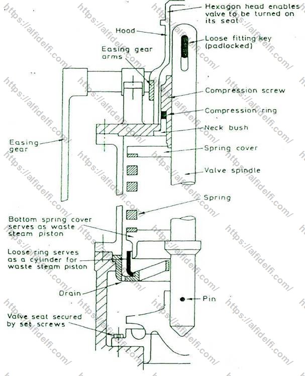
The improved high-lift safety valve has a modified arrangement around the lower spring carrier, as shown in Figure above. The lower spring carrier is arrangedLearn More
The Fig 500 High Lift Safety Valve has been designed primarily for use on unvented hot water heating systems, where a high capacity, emergency steam relief capability is required. High capacity and resilient PTFE seating, also make the Fig 500 ideal for steam, air and inert gas applications. A PTFE to Viton seating design is also available whereLearn More
The sketch shown is improve high lift safety valve . The are usually mounted 2 Nos. on a single chest. Valve , seat , spindle , compression screw and bush are made of non-corroded metalLearn More
The NABIC 500 is designed primarily for use on unvented hot water heating systems, where a high capacity, emergency steam. relief capability is required.Learn More
Description. Cast Steel Double Spring High Lift Safety Valve Cast Steel Body, Nickel Alloy Seats, Stainless steel Valve Head, Bronze Valve Head holders,Learn More
Global High Lift Safety Valve Market Sales, 2017-2022, 2023-2028, (K Units) Global top five High Lift Safety Valve companies in (%) The global High Lift Safety Valve market was valued at million in and is projected to reach US$ million by 2028, at a CAGR of % during the forecast period.Learn More
High Capacity • Full Lift • Side Discharge • Lifting Lever Size & Connections 15mm (1/2″) to 65mm (2 1/2″) BSP/NPT Duty Air • Oil • Inert Gasses • Steam • Water Materials Bronze Body • PTFE Seat Seal (Viton option) Set Pressure Range 0.69 to 12.5 bar (dependent on size) Temperature -20°C to 195°C Compliance & ApprovalsLearn More
The mode of operation is as follows: After the valve disk has been lifted, its entire area is acted upon. The resulting force lifts the valve disk. The leadership of the piston-like, valve plate 14Learn More
Bronze High Lift Safety Relief Valve – with Test Lever. SKU: V1500 Category: Pressure Relief Valves & Safety Relief Valves. Screwed BSPP, PTFE Seat,Learn More
The Nabic Fig 500SS High Lift Safety Valve offers the properties of a stainless steel valve, but without the expense. It is ideal for situations where the service fluid / media used necessitate stainless steel, but the working environment does not. The valve can be supplied either as a sealed dome or with a test lever.Learn More
Product : "SANT" Cast Iron Double Post High Lift Safety Valve Body Material cum Standard : Cast Iron IBR 86 to 93 Gr.A Description : Spring Loaded Hi Lift Type of Seat : Renewable seat Type of Disc : Renewable disc Trim : SS AISI-410 / Monel End Details : Inlet Flange to BS:10 Table F, Outlet Flange to BS:10 Table D.Learn More
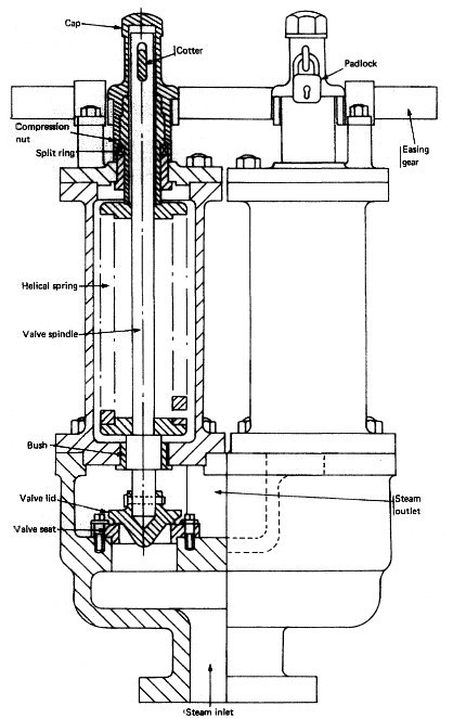
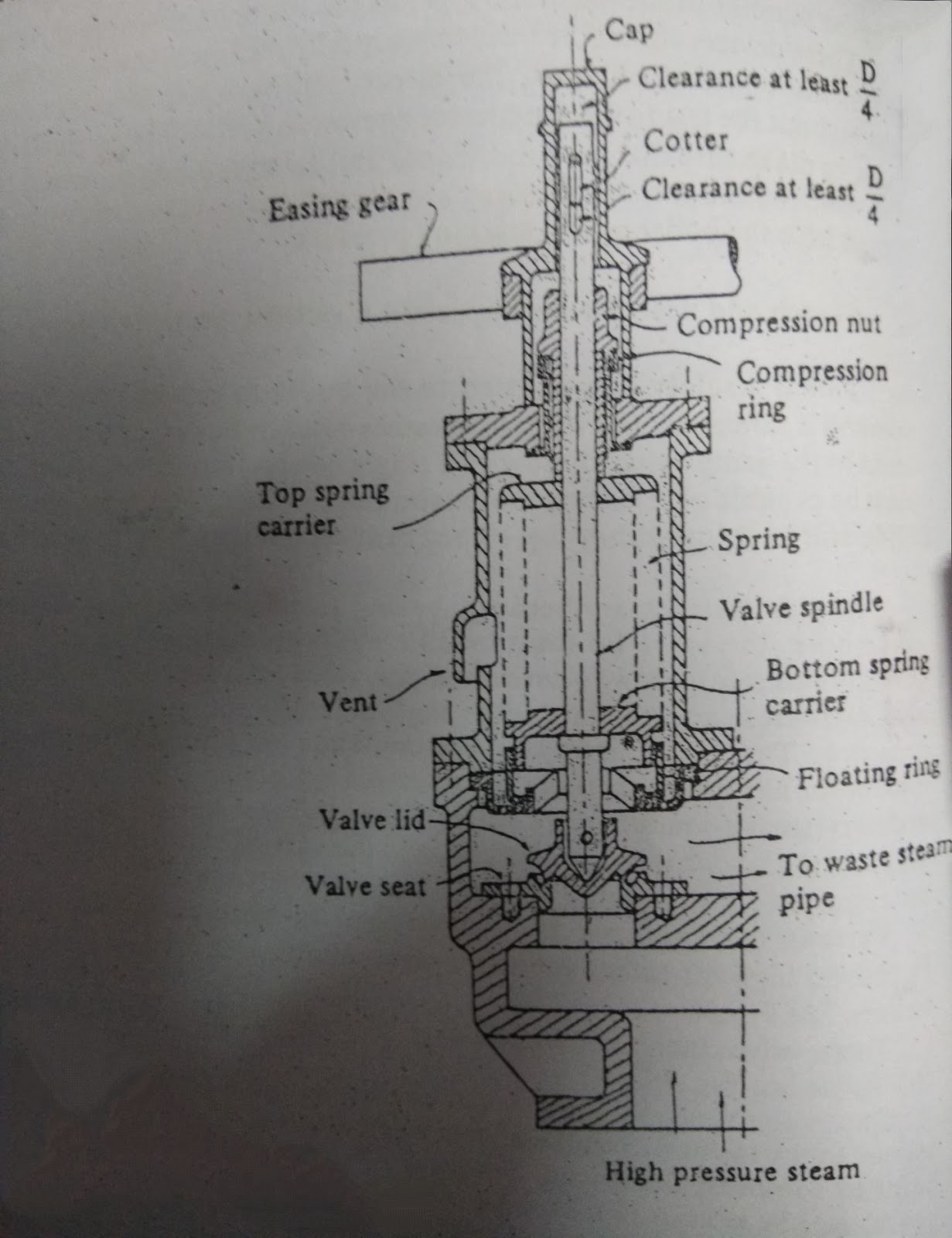
Improved high lift safety valve. It is a spring-loaded valve. Spring that produces the load is fitted under the cover with a compression nut so that any degree of compression can be given to suitLearn More
The NABIC 500 is designed primarily for use on unvented hot water heating systems, where a high capacity, emergency steam relief capability is required.Learn More
safety valve lift safety lift valve Prior art date 1940-09-12 Application number DK179541A Other languages Danish (da) Inventor Gustav Friedrich Gerdts Original Assignee Gustav Friedrich Gerdts Priority date (The priority date is an assumption and is not a legal conclusion.Learn More
The NABIC 500ST High Lift Safety Valve has been designed for applications where the properties of stainless steel are required for the service fluid beingLearn More
Typically used to safeguard boilers, vessels and pipework from the risks of higher than desired pressures protecting valuable resources and avoiding costlyLearn More
Using the maximum effective lift as ideal, typical lifts for each type of valve are: Ordinary Safety valve = D/24 High Lift Safety valve = D/16 Improved High Lift Safety valve = D/12 Full Lift Safety valve = D/5 Full Bore Relay Safety valve = D/4 Ordinary Safety Valve It has lipped valve lid to increase the lift to D/24.Learn More
High Pressure Low Lift Safety Valve. A41Y Type Low Lift Safety Valves are used for the equipment and pipeline of the air, N2, H2 Mixed gas, water and other medium with working temperature less than 200℃. Stainless Steel Trim Types are used for the equipment and pipeline of the quality with corrosive medium with working temperature less thanLearn More
F16K17/08 — Safety valves; Equalising valves, e.g. pressure relief valves opening on surplus pressure on one side; closing on insufficient pressure on one side spring-loaded with special arrangements for providing a large discharge passageLearn More
The pressure setting of the superheater safety valve should be less that the designed pressure of the boiler, i.e. less than that of the steam drum safety valve, to ensure flow of steam through the superheater under blow off conditions. The pressure setting of one steam drum safety valve should be same as the design pressure of the boiler. The pressure setting of another safety valve should be 2-3 % more than the designed pressure of the boiler.
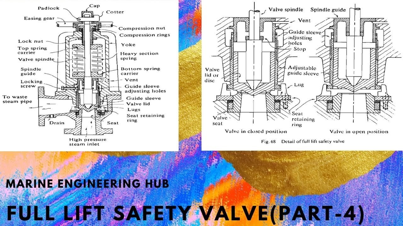
A lip is placed around the valve seat so that when the valve lid lifts, escaping steam is trapped in the annular space around the valve face, the resultant build–up of pressure acting upon the greater valve lid area causes the valve to lift sharply. This arrangement gives another advantage to close the valve cleanly and sharply with very little blow down effect.
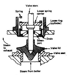
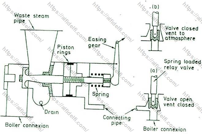
The improved high lift safety valve makes use of waste steam pressure to increase the valve lift; this is done by allowing the pressure to act upon the lower spring carrier which fits within a floating ring so forming in effect a piston. The pressure acts upon this piston causing it to move up, helping to compress the spring and so increasing the valve lift.
A cap is then fitted over the compression nut and the top of the valve spindle, a cotter is passed through and padlocked to prevent tampering by unauthorized person.
15. Valve Area (As) greater than (A) due to specific volume of steam increases with increases of temperature at constant pressure and more escape area is required to avoid accumulation of pressure.
To check the proper working condition of the boiler safety valve we carry out the “Hand trying out the Boiler Safety valve” at regular intervals. The safety valve is provided with the easing gear which manually lifts the safety valve and releases the excess pressure in the boiler. When the easing gear is pulled, the valve will be opened by hand to a full lift of ¼ D to release the boiler pressure. Before carrying out the process the boiler safety valve has to be drained.
Draining of the boiler safety valve is necessary as to prevent any build-up of water in the pipe line causing head of water to form over the valve lid so increasing the blow off pressure. So at regular intervals the boiler safety valve should be drained.
The waste steam pipe of the boiler safety valve should be well secured so that no load of the pipe is on the safety valve, which can be the cause of additional stress on the valve.
If it is found that the boiler safety relief valve is not lifting at the designed lifting pressure, manual pressure setting of the boiler safety valve has to be done for the proper and safe operation of the boiler. The adjustment can be carried out on this type of valve to give the desired discharge and blow down characteristic.
Slowly raise the boiler pressure and blow off the safety valves manually few times for thermal expansion and to reduce the thermal stress on the valves.
Raise the boiler steam pressure 2-3 % more than the designed pressure of the boiler, then stop firing and unscrew the first valve slowly, when it blows off at 2-3 % more than the designed pressure then note this opening and closing pressure of the valve and finally gag it.
Raise the boiler pressure at the designed pressure of the boiler and unscrew the 2nd valve, when it blows off at designed pressure then note this opening pressure and check the closing pressure also. Recheck the setting pressure and gag the valve.

The answer is that for boilers with a superheater on valve is mounted on the drum and the other on the superheater outlet. The superheater valve opens first to ensure that there is a flow of steam through it otherwise it would very rapidly overheat and fail. For boilers without a superheater they are mounted on drum wand would have the same pressure of as near as possible. You might give slightly different lift and blowdown settings to introduced a degree of control of water loss in slight overload conditions.
A safety valve is a valve that acts as a fail-safe. An example of safety valve is a pressure relief valve (PRV), which automatically releases a substance from a boiler, pressure vessel, or other system, when the pressure or temperature exceeds preset limits. Pilot-operated relief valves are a specialized type of pressure safety valve. A leak tight, lower cost, single emergency use option would be a rupture disk.
Safety valves were first developed for use on steam boilers during the Industrial Revolution. Early boilers operating without them were prone to explosion unless carefully operated.
Vacuum safety valves (or combined pressure/vacuum safety valves) are used to prevent a tank from collapsing while it is being emptied, or when cold rinse water is used after hot CIP (clean-in-place) or SIP (sterilization-in-place) procedures. When sizing a vacuum safety valve, the calculation method is not defined in any norm, particularly in the hot CIP / cold water scenario, but some manufacturers
Combination water meters comprises of a bulk Woltmann insert and a low-flow Volumetric insert or meter, flow is diverted between them by a by-pass valve that is set at a predetermined flow rate. This allows the combination meter to have a very large measurement range.
Whole products such as valves, boilers & showers undergo mechanical and water quality testing. This type of approval demonstrates full compliance with the requirements of the regulations and bye-laws, provided the fitting is installed according to any conditions given with the approval.
BS EN 331:2015 specifies the characteristics for the construction, performance and safety of ball valves and closed bottom taper plug valves. It also details the test methods and marking provisions. It applies to metallic valves not directly buried for domestic and commercial installations inside or outside of buildings, using gases of the first, second and third family (specified in EN 437) and working up to 0,2 × 10⁵ Pa, 0,5 × 10⁵ Pa, 1 × 10⁵Pa, 5 × 10⁵ Pa and 20 × 105Pa and with temperature limits from – 5 °C or -20 °C to + 60 °C.
Classification, verification, risk management, and technical advisory to the maritime industry on safety, enhanced performance, fuel efficiency, etc. As a classification society, DNV GL sets standards for ships and offshore structures – known as Class Rules. They comprise safety, reliability and environmental requirements that vessels and other offshore mobile structures in international waters must comply with. DNV GL is authorized by 130 maritime administrations to perform certification or verification on their behalf.
Elster Water Metering (formally Kent Meters and now part of Honeywell) are an industry leader in the manufacture of water meters, which includes high accuracy mechanical meters, fully electronic water meters and Smart metering solutions for residential, commercial and industrial sectors.
Based on the volumetric rotary piston measurement principle, these meters offer the very highest levels of reading accuracy, even at the lowest flow rate. Optimum accuracy is maintained whether the meter is installed horizontally, vertically or on an incline.
Valves have been qualified by testing to API standards 607, 4th Edition. The valve design incorporates a secondary metal seat in the body, providing the required shutoff should the primary seats be destroyed by fire.
Many of our marine valves can be pressure tested, witnessed by a classification society and supplied with 3.1 & 3.2 certifications on request, these include Lloyd’s Register of Shipping, DNV-GL (Det Norske Veritas), RINA, Bureau Veritas, Germanischer Lloyds, NK and ABS (American Bureau of Shipping). Please contact sales with your requirements.


 8613371530291