
kunkle safety valve 6010 free sample
Safety valve for over pressure protection of steam boilers operating up to 250 psi. It is rated up to 250 psi and 406�F saturated steam. 6010 Safety valves meet ASME code, Section I.
Safety relief valve for steam service on unfired pressure vessels. It is also used on accumulators, cleaners, and distillers. Safety relief valves are rated up to 250 psi and 406�F of saturated steam and meet ASME code, Section VIII.
Safety relief valve for air, gas and vapors. It is used on compressors, receivers, burners, dryers and other piping systems. Figure 6010 safety relief valves are rated up to 300 psi and 406�F and meet ASME code, Section VIII.
ASME Code Type--select--Section I; 6010DCM01-AM Steam Boiler Service, V stampSection VIII; 6010DCM01-LM Unfired Pressure Vessel Steam Service, UV stampSection VIII; 6010DCM01-KM Air Service, UV stamp

Safety valve for over pressure protection of steam boilers operating up to 250 psi. It is rated up to 250 psi and 406�F saturated steam. 6010 Safety valves meet ASME code, Section I.
Safety relief valve for steam service on unfired pressure vessels. It is also used on accumulators, cleaners, and distillers. Safety relief valves are rated up to 250 psi and 406�F of saturated steam and meet ASME code, Section VIII.
Safety relief valve for air, gas and vapors. It is used on compressors, receivers, burners, dryers and other piping systems. Figure 6010 safety relief valves are rated up to 300 psi and 406�F and meet ASME code, Section VIII.
ASME Code Type--select--Section I; 6010JJM01-AM Steam Boiler Service, V stampSection VIII; 6010JJM01-LM Unfired Pressure Vessel Steam Service, UV stampSection VIII; 6010JJM01-KM Air Service, UV stamp
Kunkle Valves is a leading manufacturer of quality safety and relief valve products for industrial and commercial applications. Kunkle products are available for ASME Section I, Section IV and Section VIII services with relief capacities certified by the National Board.
Kunkle Valve is a premier manufacturer of pressure relief valves. In fact, Erastus B. Kunkle invented the safety valve, which he patented in 1875, to prevent overpressure in locomotive engines. For almost 150 years, Kunkle Valve has been known for their high-quality products — many pieces of equipment that require valves, like boilers and air compressors, are shipped from the factory with a Kunkle Valve already installed.
The basic design of Kunkle valves is similar to that of Consolidated valves, with a disc on top of a seating surface and a spring set to relieve at a certain pressure. The major differences between the two types of valves is their size and where they are used: whereas Consolidated makes large, heavy-duty valves for industrial applications like pipelines and refineries, Kunkle makes smaller, less expensive pressure relief valves for lower-pressure commercial applications, like hospital boilers and building sprinkler systems.
Kunkle makes many different types of valves that can be used for many purposes. The entire line includes 30 or so models that are available in sizes ranging from ¼” to 6” x 8”. Within that line, they cover a lot of niche areas. For example, they have valves made of bronze, cast iron, steel, and even 316 stainless steel. Due to the material variety, the valves can be used in many applications, from sanitary applications (hospitals, food machinery) to boilers on ships, to corrosive applications like acids.
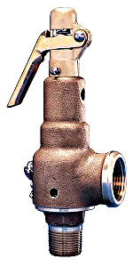
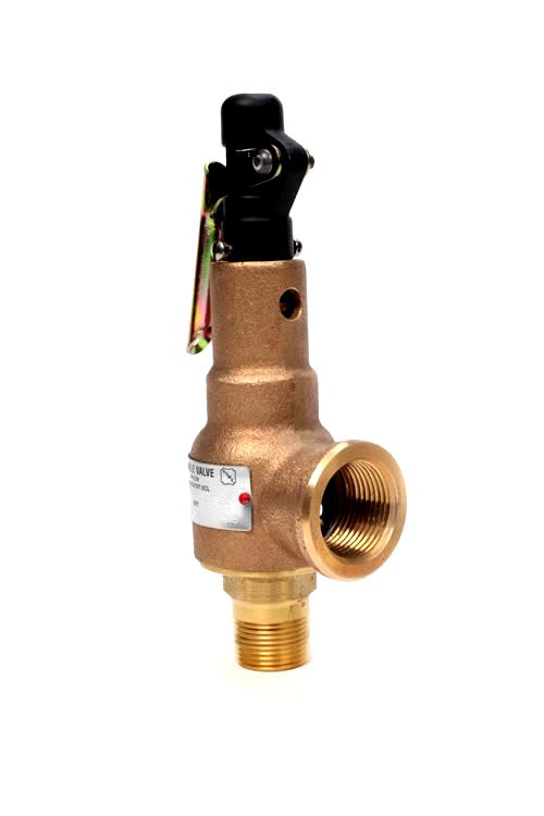
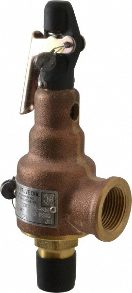
Model 6010, which is a side outlet, full nozzle valve that has bronze/brass trim (also available with a Teflon® disc insert [Model 6021] and with stainless steel trim [Model 6030]). The 6010 comes in sizes ½” to 2” and is used primarily on smaller boilers and heating systems.
Model 6252, which is a cast iron valve with an enclosed spring and stainless steel trim. The 6252 ranges from 1 ½” to 6” and is used for larger steam boilers and also sometimes for air service.
Universities are a good example of where Kunkle steam valves might be used. Many universities have a steam plant and need to transfer the generated steam to 30 or 40 buildings through underground piping. Along that piping, they may have different pressure requirements, such as 30 pounds of steam pressure to heat a dorm, but only 2 or 3 pounds to heat steam tables in the cafeteria. In this case, each pressure reducing station would be followed by a Kunkle relief valve.
Many Kunkle valves are designed for air service, such as on air compressors in auto shops and small factories where either low- or high-pressure air is required. For example, at a tire shop that uses mechanical or pneumatic tools, a Kunkle air valve would sit atop the air compressor.
Kunkle also makes valves for liquid service, which are installed on water lines after pumps. For example, in an apartment building that has a sprinkler system, relief valves are there to keep the pressure from getting too high.
View our full line of Kunkle Valve products. If you have any questions about Kunkle Valves or need help sizing and selecting the right valve for your application, give us a call or shoot us an email — we’re here to help.

1 VALVES & CONTROLS KUNKLE SAFETY VALVE PRODUCTS ASME Section I and VIII, Steam, V and UV, ASME Section VIII, Air/Gas UV National Board Certified. Models 6933, 6934, and 6935 are ASME Section IV, Steam HV National Board Certified. PED certified for non-hazardous gas. Model descriptions Model 6010 Model 6010: Side outlet. Full nozzle design with bronze/brass trim. Available with O-ring seats. For exceptional leak-free performance. Model 6021: Same as model 6010 with Teflon (PFA) disc insert. For exceptional leak-free performance (use on steam only). Model 6030: Same as model 6010 except Stainless Steel (SS) trim (nozzle and disc). Available with O-ring seats for exceptional leak-free performance. Model 6182: Top outlet. Full nozzle design with bronze/brass trim. O-ring seat available for exceptional leak-free performance. Model 6121: Same as model 6182 with Teflon (PFA) disc insert. For exceptional non-leak performance (use on steam only). Model 6130: Same as model 6182 except SS trim (nozzle and disc). O-ring seat available for exceptional leak-free performance. Model 6186: Top outlet. Full nozzle design with bronze/brass trim. 150 psig [10.3 barg] maximum set pressure. Replaces Model 86 (original equipment only). For air service only. Model 6283: Over-sized side outlet. Full nozzle design bronze/brass trim. Model 6221: Same as model 6283 with Teflon (PFA) disc insert. For exceptional leak-free performance (use on steam only). Model 6230: Same as model 6283 except SS trim (nozzle and disc). Model 6933: Same as model 6010 except certified for ASME code Section IV. Low pressure steam heating boilers set at 15 psig [1.0 barg] only. Model 6934: Same as model 6021 except certified for ASME code Section IV. Low pressure steam heating boilers set at 15 psig [1.0 barg] only. Model 6935: Same as model 6030 except certified for ASME code Section IV. Low pressure steam heating boilers set at 15 psig [1.0 barg] only. Features O-ring seats available for exceptional leakfree performance, reduced maintenance cost, multiple cycles with tight shutoff, improved seating integrity. Wide hex on valve nozzle provides wrenching service clearance for easy installation. Dual control rings offer easy adjustability for precise opening with minimum preopen or simmer and exact blowdown control. Pivot between disc and spring corrects misalignment and compensates for spring side thrust. Grooved piston model disc reduces sliding area and friction. Each Kunkle valve is tested and inspected for pressure setting and leakage. Note: 1. Resilient seats determine temperature range (see page 11). KUKMC-0394-US-1407 Copyright 2014 Pentair
2 Specifications - Models 6010, 6021, 6182, 6283, 6221, 6030, 6130 and 6230 Pressure and Temperature Limits Models 6010, 6021, 6182, 6283, 6221 Steam Service 3 to 250 psig [0.2 to 17.2 barg] -60 to 406 F [-51 to 208 C] Air/Gas Service 3 to 300 psig [0.2 to 20.7 barg] -60 to 406 F [-51 to 208 C] Models 6030, 6130, 6230 Steam and Air/Gas Service 3 to 300 psig [0.2 to 20.7 barg] -60 to 425 F [-51 to 218 C] Applications Steam Boilers and Generators. Air/Gas Compressors - reciprocating or rotary - portable or stationary, intercoolers and aftercoolers. Pressure Vessels - containing steam, air or non-hazardous gas. Including tanks, receivers, sterilizers and autoclaves. Pressure Reducing Stations - protection of the discharge or low pressure side of system. Code: A SME UV A SM E V A SME HV Parts and Materials (O-ring) Models 6010, 6030, 6182, 6130, 6186, 6283, 6230, 6933, 6935 Optional Soft Seat Models 6021, 6121, 6221, 6934 Teflon Seat Configuration Models 6010, 6030, 6283, 6230, 6933, 6935 Models 6182, 6121, 6130, 6186 Top Outlet Configuration page 2 KUKMC-0394-US-1407 Copyright 2014 Pentair
3 Parts and Materials No. Part Name Materials 1 Nozzle BRS B283-C48500 or BRZ SB Body Set Screw SS Warn Ring Set Screw SS Disc BRS B21 C Wire and Seal SS Wire and Lead Seal 6 Guide Set Screw SS Retainer Nut 2 BRS B16 8 Stem SS A for D orifice SS A for E thru J orifice 9 Body BRZ B584-C Lever STL A109 or JIS SPCC Equivalent/ZN Plated Yellow 11 Jam Nut BRS B16 12 Lift Nut STL A /ZN Plated 13 Cap Aluminum, Anodized 14 Lever Pin STL A108-12L14 15 Cap Set Screw SS Compression Screw BRS B16 17 Spring ASTM A-313 TY Spring Step BRS B16 19 Stem Retainer BRS B16 20 Guide BRS B16 for D and E Orifice BRS B283-C37700 for F through J Orifice 21 Warn Ring 7 BRS B16 22 Seat Note 1 23 Seat Retainer BRS B Disc 8 BRS B21 C Warn Ring Spring 6 SS A / Gag Screw 9 STL A /ZN Plated Notes: 1. Models 6021, 6121, 6221 and 6934 Teflon, optional O-ring seat available for all others. 2. Section IV only. 3. Models 6030, 6130, 6230 and 6935 are SS SA351-CF8. 4. Models 6030, 6130, 6230 and 6935 are SS SA (D through H Orifice) or SS SA (J Orifice). 6. Variation 02 (vibration dampening) only. 7. Soft seat D, E and F orifice require special warn ring (notch on O.D. of fins). 8. Applies only to elastomer soft seat options. 9. Applies only to gag options. Remove when valve is in service. Failure to remove gag screw may cause serious damage to equipment, person injury, and death. 5. Models 6030, 6130, 6230 and 6935 are SS SA Copyright 2014 Pentair KUKMC-0394-US-1407 page 3
4 Specifications Model Orifice Connections Valve Dimensions Approximate Number1 ANSI Standard in [mm] Weight Inlet Outlet A B C lb [kg] in [mm] in [mm] 60**DC# D 1/2 [12.7] 3/4 [19.0] 2 1 /8 [54] 1 5 /8 [41] 6 1 /2 [165] 1 1 /2 [0.7] 60**DD# 2 D 3/4 [19.0] 3/4 [19.0] 2 1 /8 [54] 1 5 /8 [41] 6 1 /2 [165] 1 3 /4 [0.8] 61**DC# D 1/2 [12.7] 6 1 /2 [165] 1 1 /4 [0.6] 60**ED# E 3/4 [19.0] 1 [25.4] 2 3 /8 [60] 1 3 /4 [44] 7 1 /2 [191] 2 1 /2 [1.1] 60**EE# 2 E 1 [25.4] 1 [25.4] 2 1 /2 4 [64] 1 3 /4 [44] 7 5 /8 5 [194] 2 3 /4 [1.2] 61**ED# E 3/4 [19.0] 7 1 /2 [191] 2 1 /4 [1.0] 62**ED# E 3/4 [19.0] 1 1 /4 [31.75] 2 7 /8 [73] 1 3 /4 [44] 7 1 /2 [191] 2 3 /4 [1.2] 60**FE# F 1 [25.4] 1 1 /4 [31.8] 2 5 /8 [67] 2 [51] 8 1 /2 [216] 3 1 /2 [1.6] 60**FF# 2 F 1 1 /4 [31.8] 1 1 /4 [31.8] 2 7 /8 [73] 2 [51] 8 3 /4 [222] 3 3 /4 [1.7] 61**FE# F 1 [25.4] 8 1 /2 [222] 3 1 /4 [1.5] 62**FE# F 1 [25.4] 1 1 /2 [38.0] 2 7 /8 [73] 2 [51] 8 1 /2 [222] 3 3 /4 [1.7] 60**GF# G 1 1 /4 [31.8] 1 1 /2 [38.0] 3 1 /8 [79] 2 3 /8 [60] 9 5 /8 [244] 5 1 /2 [2.5] 60**GG# 2 G 1 1 /2 [38.0] 1 1 /2 [38.0] 3 3 /8 [86] 2 3 /8 [60] 10 [254] 5 3 /4 [2.6] 61**GF# G 1 1 /4 [31.8] 9 5 /8 [244] 5 [2.3] 62**GF# G 1 1 /4 [31.8] 2 [51.0] 3 3 /8 [86] 2 1 /4 [57] 9 5 /8 [244] 5 3 /4 [2.6] 60**HG# H 1 1 /2 [38.0] 2 [51.0] 3 5 /8 [92] 2 3 /4 [70] 10 5 /8 [270] 7 3 /4 [3.5] 60**HH# 2 H 2 [51.0] 2 [51.0] 4 1 /8 [105] 2 3 /4 [70] 11 1 /8 [283] 8 [3.6] 61**HG# H 1 1 /2 [38.0] 10 5 /8 [270] 7 1 /4 [3.3] 62**HG# H 1 1 /2 [38.0] 2 1 /2 [64.0] 3 7 /8 [98] 3 [76] 10 5 /8 [270] 8 [3.6] 60**JH# J 2 [51.0] 2 1 /2 [64.0] 4 1 /4 [108] 3 3 /8 [86] 13 5 /8 [346] 15 1 /2 [7.0] 60**JJ# 2 J 2 1 /2 [64.0] 2 1 /2 [64.0] 4 1 /2 [114] 3 3 /8 [86] 14 [356] 15 3 /4 [7.2] 61**JH# J 2 [51.0] 13 5 /8 [346] 15 [6.8] 62**JH# J 2 [51.0] 3 [76.0] 4 5 /8 [117] 3 3 /8 [86] 13 5 /8 [345] 15 1 /2 [7.0] Dimensions are for reference only. Notes: 1. Replace asterisks with desired model number. Replace # with desired seat material. 2. Model 6030 and 6935 available only 1 /2 x 3 /4" [12.7 x 19 mm], 3 /4 x 1" [19 x 25.4 mm], 1 x 1 1 /4" [25.4 x 31.8 mm], 1 1 /4 x 1 1 /2" [31.8 x 38 mm], 1 1 /2 x 2" [38 x 51 mm] and 2 x 2 1 /2" [51 x 64 mm]. C 3. Models 6933, 6934 and 6935 have same dimensions as model /4" for BSP [57]. A /8" for BSP [192.5]. B page 4 KUKMC-0394-US-1407 Copyright 2014 Pentair
12 Ordering Information ASME Section I and VIII, Steam, ASME Section VIII, Air/Gas National Board Certified. Models 6933, 6934, 6935 ASME Section IV, National Board Certified Model Number/Order Guide Model Number Position Example H G M 0 1 A M Model Orifice D E F G H J Inlet Size C - 1 /2" [12.7] G /2" [38.1] D - 3 /4" [19.0] H - 2" [50.8] E - 1" [25.4] J /2" [63.5] F /4" [31.8] Seat Material M - Metal T - Teflon (Models 6021, E - EPR 6121, 6221, 6934 only) V - Viton Variation (01 to 99) 01 - Plain lever 02 - Plain lever with vibration dampener 03 - Plain lever with gag 60 - BSP Threads Design Revision Indicates non-interchangeable revision. Dash (-) if original design. Valve Service A - Steam ASME Section I K - Air/Gas ASME Section VIII L - Steam ASME Section VIII G - Steam ASME Section IV (Models 6933, 6934, 6935 only) P - Steam, Non-code N - Air, Non-code Spring Material M - SS Set Pressure psig [1.0 barg] only for Models 6933, 6934, 6935 VALVES & CONTROLS KUNKLE FACILITY PHONE: All Pentair trademarks and logos are owned by Pentair, Inc. All other brand or product names are trademarks or registered marks of their respective owners. Because we are continuously improving our products and services, Pentair reserves the right to change specifications without prior notice. Pentair is an equal opportunity employer. page 12 KUKMC-0394-US-1407 Copyright 2014 Pentair

Safety is of the utmost importance when dealing with pressure relief valves. The valve is designed to limit system pressure, and it is critical that they remain in working order to prevent an explosion. Explosions have caused far too much damage in companies over the years, and though pressurized tanks and vessels are equipped with pressure relief vales to enhance safety, they can fail and result in disaster.
That’s also why knowing the correct way to test the valves is important. Ongoing maintenance and periodic testing of pressurized tanks and vessels and their pressure relief valves keeps them in working order and keep employees and their work environments safe. Pressure relief valves must be in good condition in order to automatically lower tank and vessel pressure; working valves open slowly when the pressure gets high enough to exceed the pressure threshold and then closes slowly until the unit reaches the low, safe threshold. To ensure the pressure relief valve is in good working condition, employees must follow best practices for testing them including:
If you consider testing pressure relief valves a maintenance task, you’ll be more likely to carry out regular testing and ensure the safety of your organization and the longevity of your
It’s important to note, however, that the American Society of Mechanical Engineers (ASME) and National Board Inspection Code (NBIC), as well as state and local jurisdictions, may set requirements for testing frequency. Companies are responsible for checking with these organizations to become familiar with the testing requirements. Consider the following NBIC recommendations on the frequency for testing relief valves:
High-temperature hot water boilers (greater than 160 psi and/or 250 degrees Fahrenheit) – pressure test annually to verify nameplate set pressure. For safety reasons, removal and testing on a test bench is recommended
When testing the pressure relief valve, raise and lower the test lever several times. The lever will come away from the brass stem and allow hot water to come out of the end of the drainpipe. The water should flow through the pipe, and then you should turn down the pressure to stop the leak, replace the lever, and then increase the pressure.
One of the most common problems you can address with regular testing is the buildup of mineral salt, rust, and corrosion. When buildup occurs, the valve will become non-operational; the result can be an explosion. Regular testing helps you discover these issues sooner so you can combat them and keep your boiler and valve functioning properly. If no water flows through the pipe, or if there is a trickle instead of a rush of water, look for debris that is preventing the valve from seating properly. You may be able to operate the test lever a few times to correct the issue. You will need to replace the valve if this test fails.
When testing relief valves, keep in mind that they have two basic functions. First, they will pop off when the pressure exceeds its safety threshold. The valve will pop off and open to exhaust the excess pressure until the tank’s pressure decreases to reach the set minimum pressure. After this blowdown process occurs, the valve should reset and automatically close. One important testing safety measure is to use a pressure indicator with a full-scale range higher than the pop-off pressure.
Thus, you need to be aware of the pop-off pressure point of whatever tank or vessel you test. You always should remain within the pressure limits of the test stand and ensure the test stand is assembled properly and proof pressure tested. Then, take steps to ensure the escaping pressure from the valve is directed away from the operator and that everyone involved in the test uses safety shields and wears safety eye protection.
After discharge – Because pressure relief valves are designed to open automatically to relieve pressure in your system and then close, they may be able to open and close multiple times during normal operation and testing. However, when a valve opens, debris may get into the valve seat and prevent the valve from closing properly. After discharge, check the valve for leakage. If the leakage exceeds the original settings, you need to repair the valve.
According to local jurisdictional requirements – Regulations are in place for various locations and industries that stipulate how long valves may operate before needing to be repair or replaced. State inspectors may require valves to be disassembled, inspected, repaired, and tested every five years, for instance. If you have smaller valves and applications, you can test the valve by lifting the test lever. However, you should do this approximately once a year. It’s important to note that ASME UG136A Section 3 requires valves to have a minimum of 75% operating pressure versus the set pressure of the valve for hand lifting to be performed for these types of tests.
Depending on their service and application– The service and application of a valve affect its lifespan. Valves used for clean service like steam typically last at least 20 years if they are not operated too close to the set point and are part of a preventive maintenance program. Conversely, valves used for services such as acid service, those that are operated too close to the set point, and those exposed to dirt or debris need to be replaced more often.
Pressure relief valves serve a critical role in protecting organizations and employees from explosions. Knowing how and when to test and repair or replace them is essential.


 8613371530291