
leser safety valve manual pdf quotation
ENGINEERING is the technical manual for safety valves from LESER. The extensive collection offers you information for almost all areas around the safety valve and is aimed at both occasional and advanced users. Learn interesting facts and information on safety valves.
You want to maintain or repair a LESER Safety Valve? Then MAINTENANCE offers you an extensive range of documents for the maintenance and repair of the LESER product groups.
Large orifice closed bonnet pressure relief valves. Also available with open bonnet as Styles HS/HSU; and as large orifice pilot operated pressure relief valves. Style JPV-A, for air, gas and steam. Ask for Catalog No. 307. Specifications:
A unique, completely sealed pressure relief valve for transportation and storage of chlorine and other toxic and corrosive fluids. Ask for Catalog No. 306. Specifications:
A sanitary pressure/vacuum pressure relief valve for the beverage, food processing and pharmaceutical industries. This valve provides three modes of self actuated operation:
Non-flowing, snap-acting, pilot operated, pressure relief valves. High performance valves for overpressure protection of pipes and vessels containg gases and vapors. Ask for Catalog No. 318. Specifications:
Non-flowing, modulating, pilot operated, pressure relief valve. Used for overpressure protection of gas, vapor, liquid and steam. Mounted on the same main valve used with Style JPV. Ask for Catalog No. 318. Specifications:
Non-flowing, modulating, pilot operated, pressure relief valve. Used for overpressure protection of high temperature fluids including hydrocarbons, inert gases and steam. Ask for Catalog No. 318. Specifications:
Pressure relief valve with single trim for liquid, gas and steam service. Precision lapped flat metal to metal seats or elastomer and TFE O-ring soft seats provide the ultimate in seat tightness. Blowdown is typically less than 20%. Capacities certified by National Board of Boiler and Pressure Vessel Inspectors. Ask for Catalog No. 902. Specifications:
Series 800 pressure relief valves are designed for use on air, gas, vapor and steam service. External precise blowdown control provides shorter blowdown then the Series 900, typically in the range of 5 to 15 percent. Capacities certified by National Board of Boiler and Pressure Vessel Inspectors. Ask for Catalog No. 902. Specifications:
Nozzle type safety valve for saturated and superheated steam service. Seat tightness up to 95% of valve set pressure. Ask for Catalog No. 408. Specifications:
Protect superheaters from overheating during startup, prolong the life and reduce maintenace of safety valves. Ask for Catalog No. 403. Specifications:
A safety valve is a valve that acts as a fail-safe. An example of safety valve is a pressure relief valve (PRV), which automatically releases a substance from a boiler, pressure vessel, or other system, when the pressure or temperature exceeds preset limits. Pilot-operated relief valves are a specialized type of pressure safety valve. A leak tight, lower cost, single emergency use option would be a rupture disk.
Safety valves were first developed for use on steam boilers during the Industrial Revolution. Early boilers operating without them were prone to explosion unless carefully operated.
Vacuum safety valves (or combined pressure/vacuum safety valves) are used to prevent a tank from collapsing while it is being emptied, or when cold rinse water is used after hot CIP (clean-in-place) or SIP (sterilization-in-place) procedures. When sizing a vacuum safety valve, the calculation method is not defined in any norm, particularly in the hot CIP / cold water scenario, but some manufacturers
The earliest and simplest safety valve was used on a 1679 steam digester and utilized a weight to retain the steam pressure (this design is still commonly used on pressure cookers); however, these were easily tampered with or accidentally released. On the Stockton and Darlington Railway, the safety valve tended to go off when the engine hit a bump in the track. A valve less sensitive to sudden accelerations used a spring to contain the steam pressure, but these (based on a Salter spring balance) could still be screwed down to increase the pressure beyond design limits. This dangerous practice was sometimes used to marginally increase the performance of a steam engine. In 1856, John Ramsbottom invented a tamper-proof spring safety valve that became universal on railways. The Ramsbottom valve consisted of two plug-type valves connected to each other by a spring-laden pivoting arm, with one valve element on either side of the pivot. Any adjustment made to one of valves in an attempt to increase its operating pressure would cause the other valve to be lifted off its seat, regardless of how the adjustment was attempted. The pivot point on the arm was not symmetrically between the valves, so any tightening of the spring would cause one of the valves to lift. Only by removing and disassembling the entire valve assembly could its operating pressure be adjusted, making impromptu "tying down" of the valve by locomotive crews in search of more power impossible. The pivoting arm was commonly extended into a handle shape and fed back into the locomotive cab, allowing crews to "rock" both valves off their seats to confirm they were set and operating correctly.
Safety valves also evolved to protect equipment such as pressure vessels (fired or not) and heat exchangers. The term safety valve should be limited to compressible fluid applications (gas, vapour, or steam).
For liquid-packed vessels, thermal relief valves are generally characterized by the relatively small size of the valve necessary to provide protection from excess pressure caused by thermal expansion. In this case a small valve is adequate because most liquids are nearly incompressible, and so a relatively small amount of fluid discharged through the relief valve will produce a substantial reduction in pressure.
Flow protection is characterized by safety valves that are considerably larger than those mounted for thermal protection. They are generally sized for use in situations where significant quantities of gas or high volumes of liquid must be quickly discharged in order to protect the integrity of the vessel or pipeline. This protection can alternatively be achieved by installing a high integrity pressure protection system (HIPPS).
In the petroleum refining, petrochemical, chemical manufacturing, natural gas processing, power generation, food, drinks, cosmetics and pharmaceuticals industries, the term safety valve is associated with the terms pressure relief valve (PRV), pressure safety valve (PSV) and relief valve.
The generic term is Pressure relief valve (PRV) or pressure safety valve (PSV). PRVs and PSVs are not the same thing, despite what many people think; the difference is that PSVs have a manual lever to open the valve in case of emergency.
Relief valve (RV): an automatic system that is actuated by the static pressure in a liquid-filled vessel. It specifically opens proportionally with increasing pressure
Pilot-operated safety relief valve (POSRV): an automatic system that relieves on remote command from a pilot, to which the static pressure (from equipment to protect) is connected
Low pressure safety valve (LPSV): an automatic system that relieves static pressure on a gas. Used when the difference between the vessel pressure and the ambient atmospheric pressure is small.
Vacuum pressure safety valve (VPSV): an automatic system that relieves static pressure on a gas. Used when the pressure difference between the vessel pressure and the ambient pressure is small, negative and near to atmospheric pressure.
Low and vacuum pressure safety valve (LVPSV): an automatic system that relieves static pressure on a gas. Used when the pressure difference is small, negative or positive and near to atmospheric pressure.
In most countries, industries are legally required to protect pressure vessels and other equipment by using relief valves. Also, in most countries, equipment design codes such as those provided by the ASME, API and other organizations like ISO (ISO 4126) must be complied with. These codes include design standards for relief valves and schedules for periodic inspection and testing after valves have been removed by the company engineer.
Today, the food, drinks, cosmetics, pharmaceuticals and fine chemicals industries call for hygienic safety valves, fully drainable and Cleanable-In-Place. Most are made of stainless steel; the hygienic norms are mainly 3A in the USA and EHEDG in Europe.
The first safety valve was invented by Denis Papin for his steam digester, an early pressure cooker rather than an engine.steelyard" lever a smaller weight was required, also the pressure could easily be regulated by sliding the same weight back and forth along the lever arm. Papin retained the same design for his 1707 steam pump.Greenwich in 1803, one of Trevithick"s high-pressure stationary engines exploded when the boy trained to operate the engine left it to catch eels in the river, without first releasing the safety valve from its working load.
Although the lever safety valve was convenient, it was too sensitive to the motion of a steam locomotive. Early steam locomotives therefore used a simpler arrangement of weights stacked directly upon the valve. This required a smaller valve area, so as to keep the weight manageable, which sometimes proved inadequate to vent the pressure of an unattended boiler, leading to explosions. An even greater hazard was the ease with which such a valve could be tied down, so as to increase the pressure and thus power of the engine, at further risk of explosion.
Although deadweight safety valves had a short lifetime on steam locomotives, they remained in use on stationary boilers for as long as steam power remained.
Weighted valves were sensitive to bouncing from the rough riding of early locomotives. One solution was to use a lightweight spring rather than a weight. This was the invention of Timothy Hackworth on his leaf springs.
These direct-acting spring valves could be adjusted by tightening the nuts retaining the spring. To avoid tampering, they were often shrouded in tall brass casings which also vented the steam away from the locomotive crew.
The Salter coil spring spring balance for weighing, was first made in Britain by around 1770.spring steels to make a powerful but compact spring in one piece. Once again by using the lever mechanism, such a spring balance could be applied to the considerable force of a boiler safety valve.
The spring balance valve also acted as a pressure gauge. This was useful as previous pressure gauges were unwieldy mercury manometers and the Bourdon gauge had yet to be invented.
Paired valves were often adjusted to slightly different pressures too, a small valve as a control measure and the lockable valve made larger and permanently set to a higher pressure, as a safeguard.Sinclair for the Eastern Counties Railway in 1859, had the valve spring with pressure scale behind the dome, facing the cab, and the locked valve ahead of the dome, out of reach of interference.
In 1855, John Ramsbottom, later locomotive superintendent of the LNWR, described a new form of safety valve intended to improve reliability and especially to be tamper-resistant. A pair of plug valves were used, held down by a common spring-loaded lever between them with a single central spring. This lever was characteristically extended rearwards, often reaching into the cab on early locomotives. Rather than discouraging the use of the spring lever by the fireman, Ramsbottom"s valve encouraged this. Rocking the lever freed up the valves alternately and checked that neither was sticking in its seat.
A drawback to the Ramsbottom type was its complexity. Poor maintenance or mis-assembly of the linkage between the spring and the valves could lead to a valve that no longer opened correctly under pressure. The valves could be held against their seats and fail to open or, even worse, to allow the valve to open but insufficiently to vent steam at an adequate rate and so not being an obvious and noticeable fault.Rhymney Railway, even though the boiler was almost new, at only eight months old.
Naylor valves were introduced around 1866. A bellcrank arrangement reduced the strain (percentage extension) of the spring, thus maintaining a more constant force.L&Y & NER.
All of the preceding safety valve designs opened gradually and had a tendency to leak a "feather" of steam as they approached "blowing-off", even though this was below the pressure. When they opened they also did so partially at first and didn"t vent steam quickly until the boiler was well over pressure.
The quick-opening "pop" valve was a solution to this. Their construction was simple: the existing circular plug valve was changed to an inverted "top hat" shape, with an enlarged upper diameter. They fitted into a stepped seat of two matching diameters. When closed, the steam pressure acted only on the crown of the top hat, and was balanced by the spring force. Once the valve opened a little, steam could pass the lower seat and began to act on the larger brim. This greater area overwhelmed the spring force and the valve flew completely open with a "pop". Escaping steam on this larger diameter also held the valve open until pressure had dropped below that at which it originally opened, providing hysteresis.
These valves coincided with a change in firing behaviour. Rather than demonstrating their virility by always showing a feather at the valve, firemen now tried to avoid noisy blowing off, especially around stations or under the large roof of a major station. This was mostly at the behest of stationmasters, but firemen also realised that any blowing off through a pop valve wasted several pounds of boiler pressure; estimated at 20 psi lost and 16 lbs or more of shovelled coal.
Pop valves derived from Adams"s patent design of 1873, with an extended lip. R. L. Ross"s valves were patented in 1902 and 1904. They were more popular in America at first, but widespread from the 1920s on.
Although showy polished brass covers over safety valves had been a feature of steam locomotives since Stephenson"s day, the only railway to maintain this tradition into the era of pop valves was the GWR, with their distinctive tapered brass safety valve bonnets and copper-capped chimneys.
Developments in high-pressure water-tube boilers for marine use placed more demands on safety valves. Valves of greater capacity were required, to vent safely the high steam-generating capacity of these large boilers.Naylor valve) became more critical.distilled feedwater and also a scouring of the valve seats, leading to wear.
High-lift safety valves are direct-loaded spring types, although the spring does not bear directly on the valve, but on a guide-rod valve stem. The valve is beneath the base of the stem, the spring rests on a flange some height above this. The increased space between the valve itself and the spring seat allows the valve to lift higher, further clear of the seat. This gives a steam flow through the valve equivalent to a valve one and a half or twice as large (depending on detail design).
The Cockburn Improved High Lift design has similar features to the Ross pop type. The exhaust steam is partially trapped on its way out and acts on the base of the spring seat, increasing the lift force on the valve and holding the valve further open.
To optimise the flow through a given diameter of valve, the full-bore design is used. This has a servo action, where steam through a narrow control passage is allowed through if it passes a small control valve. This steam is then not exhausted, but is passed to a piston that is used to open the main valve.
There are safety valves known as PSV"s and can be connected to pressure gauges (usually with a 1/2" BSP fitting). These allow a resistance of pressure to be applied to limit the pressure forced on the gauge tube, resulting in prevention of over pressurisation. the matter that has been injected into the gauge, if over pressurised, will be diverted through a pipe in the safety valve, and shall be driven away from the gauge.
There is a wide range of safety valves having many different applications and performance criteria in different areas. In addition, national standards are set for many kinds of safety valves.
Safety valves are required on water heaters, where they prevent disaster in certain configurations in the event that a thermostat should fail. Such a valve is sometimes referred to as a "T&P valve" (Temperature and Pressure valve). There are still occasional, spectacular failures of older water heaters that lack this equipment. Houses can be leveled by the force of the blast.
Pressure cookers usually have two safety valves to prevent explosions. On older designs, one is a nozzle upon which a weight sits. The other is a sealed rubber grommet which is ejected in a controlled explosion if the first valve gets blocked. On newer generation pressure cookers, if the steam vent gets blocked, a safety spring will eject excess pressure and if that fails, the gasket will expand and release excess pressure downwards between the lid and the pan. Also, newer generation pressure cookers have a safety interlock which locks the lid when internal pressure exceeds atmospheric pressure, to prevent accidents from a sudden release of very hot steam, food and liquid, which would happen if the lid were to be removed when the pan is still slightly pressurised inside (however, the lid will be very hard or impossible to open when the pot is still pressurised).
12 Markings Contents 12.1 Introduction....................................................................................................................12.1-1 12.2 Purpose of Markings......................................................................................................12.2-1 12.3 Markings on Nameplates ...............................................................................................12.3-1 12.3.1 Current LESER Nameplates for Spring Loaded Safety Valves .................................12.3-2 12.3.2 Obsolete LESER Nameplates ..................................................................................12.3-4 12.4 Safety Valve Tag ...........................................................................................................12.4-1 12.5 Markings on the Safety Valve ........................................................................................12.5-1 12.5.1 Markings on Flanged Safety Valves .........................................................................12.5-2 12.5.2 Markings on Threaded Safety Valves.......................................................................12.5-2 12.6 Optional Customised Markings ......................................................................................12.6-1 12.6.1 Marking with Stainless Steel Tag .............................................................................12.6-1 12.6.2 Marking with Tag Provided by Customer..................................................................12.6-1 12.7 Markings on Internal Parts .............................................................................................12.7-1 12.7.1 Markings of Disc ......................................................................................................12.7-1 12.7.2 Markings of Disc – Short Code for Small Sizes ........................................................12.7-1 12.7.3 Markings of the Soft Seal Material on the Disc .........................................................12.7-2 12.7.4 Markings of Nozzle...................................................................................................12.7-3 12.7.5 Markings of Inlet body ..............................................................................................12.7-3 12.7.6 Markings of Spring ...................................................................................................12.7-4 12.8 Obsolete LESER Safety Valves .....................................................................................12.8-1
12 Markings 12.1 Introduction A number of worldwide recognised codes and standards require specific markings on the nameplate and body of the safety valve. The scope of this chapter is to provide an overview about the markings on LESER safety valves and to describe which information can be found where on the safety valve. Markings that are required by codes and standards as well as LESER standard markings are considered “standard” at LESER. Additional markings on customer request are listed as “Option Code” in this document.
12 Markings 12.2 Purpose of Markings Markings on safety valves have different purposes. The following table lists some purposes exemplarily: Purpose Identification of approvals Identification of the valve Tracing of materials Identification of performance features Identification of sizes Identification of the pressure rating Identification of the application Product liability Material identification Identification of parts Identification of service conditions Identification of manufacturer Identification of casting supplier
Example TÜV-approval no.; UV-Stamp Model-No., Serial-No., Tag-No. Heat-No., Material Code-No. Coefficient of discharge, capacities Nominal diameter PN, CL Steam, gases, liquids Stamped seal Material designation Part-No. Set pressure, CDTP, back pressure, temperature LESER A
12 Markings 12.3 Markings on Nameplates Every safety valve has to be marked with a name plate. Several codes and standards contain requirements for the marking of nameplates, e.g.: o o o o o
These codes and standards differ in some requirements. LESER combines these requirements and uses only one nameplate which fulfils all requirements. The LESER Name plate for Global Application NGA is the first name plate worldwide, which fulfils all requirements of the leading international codes and standards. Basically the LESER NGA is valid worldwide, but additional country-specific requirements e.g. for Russia or Canada have to be considered. Fixing of NGA The LESER Name plate for Global Application is spot welded at the bonnet of the safety valve, or at the outlet body (Series 437 and Type 481).
12 Markings 12.3.1 Current LESER Nameplates for Spring Loaded Safety Valves LESER-Nameplate for global application “NGA”, valid since January 2009 Dimensions: 60 x 40 mm/ 2,36 x 1,58 in 3
Name of manufacturer Optional marking of valve (customer"s specifications) Type number (article number) Nominal diameter Internal No. for Identification of the safety valve Flow area in mm² Flow diameter in mm Identification of the soft seal material Code letter O-Ring-Disc + Option code No entry: metal-to-metal Set pressure of the safety valve in bar Set pressure of the safety valve in psig Back pressure in bar Back pressure in psig Cold differential test pressure in bar Cold differential test pressure in psig Temperature in °C (for CDTP) Temperature in °F (for CDTP) Smallest lift / reduced lift when lift restriction in mm TÜV Approval No. according to the VdTÜV-Merkblatt + List number Date of manufacturing Month/Year Number of the standard Certified coefficient of discharge for steam (Kdr/ αw) / reduced coefficient of discharge when lift restriction Opening pressure difference in % Certified coefficient of discharge for gases(Kdr/ αw) / reduced coefficient of discharge when lift stopper Opening pressure difference in % Certified coefficient of discharge for liquids (Kdr/ αw)/ reduced coefficient of discharge when lift restriction Opening pressure difference in %
Capacity for steam 1) Capacity for gases (explicitely: air @ 60°F) 1) Capacity for liquids (explicitely: water @ 70°F) Space for additional customised information, e.g. Option codes bellows, oil and grease-free If repaired valve: Repair-No. Used for pressures in non code units CE-Marking Registration number of the notified body Sign of conformity π acc. to directive 1999/36/EG about Transportable Pressure Equipment Directive 0 (TPED) ASME + UV-Stamp Code case 2408 for UV-Stamp (UV-stamp is lasered) Marking of National Board
Table 12.3.1-1: Description of nameplate markings * = Standard 1) Capacity is marked only for one medium (steam, air or water) according to the service medium of the valve 2) Since January 2012 no longer applied
12 Markings 12.3.2 Obsolete LESER Nameplates LESER has improved the nameplates and continuously adapted to the national and international standards. The following overview of the nameplates is to lighten the identification of older LESER safety valves. In special cases it might help to make a picture of the mane plate and/ or the complete safety valve. Nameplate before 1990 3
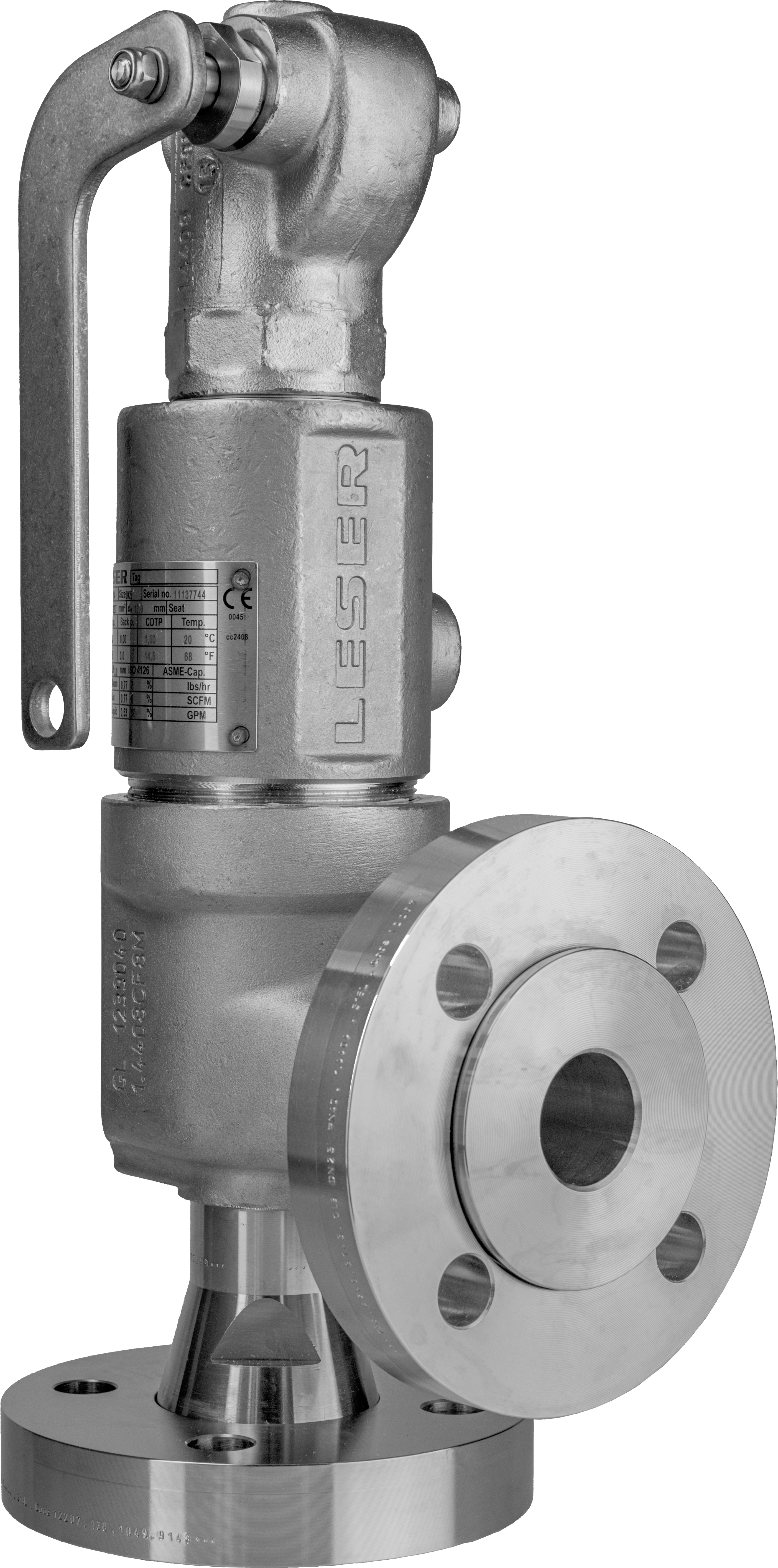
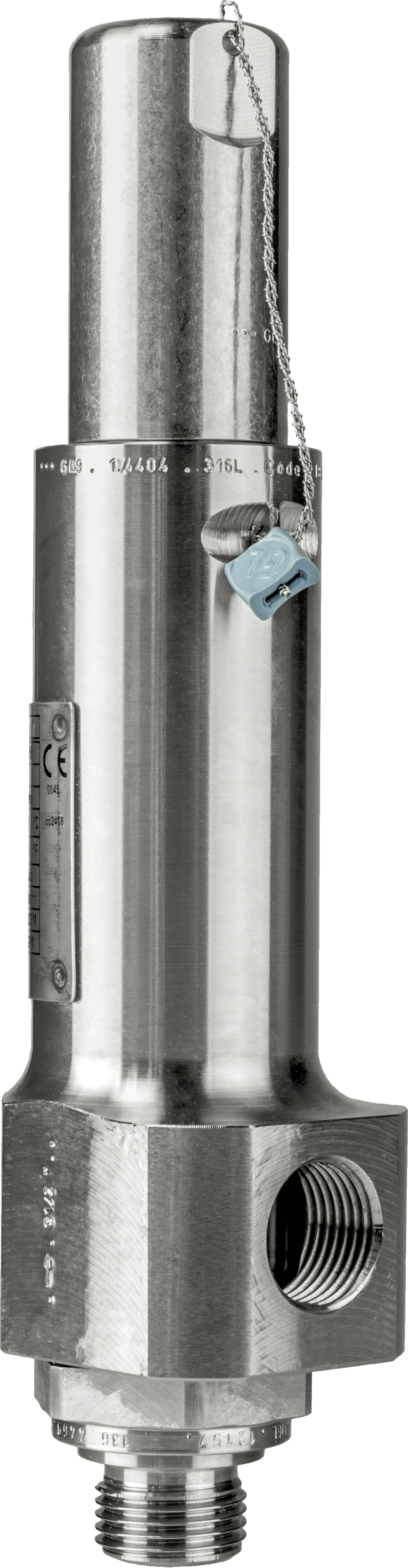
12 Markings 12.4 Safety Valve Tag Dimensions: 85 x 126 mm/ 3,35 x 4,96 in Attached to every LESER safety valve is a conditionally weatherproof tag. It gives a brief overview about the safety valve and order data for easy identification of the safety valve. It provides additional information to the information on the name plate, e.g. all option codes describing the configuration of the safety valves. Also the installed spring part number is printed on the tag.
The tag is fastened with a plastic clip at the bore hole of the lifting lever respectively at a bore hole of the outlet flange. It may remain at the valve or be stored in a proper location for documentation and future reference.
Your order number Your item number Space for your optional information as e.g. installation location, etc. (max. 3 x 30 letters) LESER-Job-Number LESER item number Article-Number Your optional marking of the valve (max. 30 letters) All option codes for the safety valve; identify connections and options.
9 Spring No. Spring(s) fitted in safety valve 10 Set pressure Set pressure of valve 11 CDTP Cold differential test pressure 12 Body material Material of safety valve body 13 Nominal size - Inlet Description of safety valve connection 14 Nominal size - Outlet Description of safety valve connection 15 Pressure rating - Inlet Description of safety valve connection 16 Pressure rating - Outlet Description of safety valve connection 17 Serial-No. Number for identification 18 LESER-Job-No. LESER-Job-Number. 19 Item-No. LESER-Job-Number 20 Barcode For LESER-internal identification of the item Table 12.4-1: Description of tag markings
12 Markings 12.5 Markings on the Safety Valve Different parts of the safety valve have to be marked with specific information. In different standards the marking of the body is defined, e.g.: o o o o
These standards differ in some requirements. It is shown which of the stated standards requires which information on the safety valve. LESER combines these requirements so every safety valve can be used worldwide. Furthermore LESER provides the customer to add optional markings on the safety valve.
Mark of valve manufacturer (“GL”) Material-No. LESER-Part-ID Arrow (flow direction) Date of casting Nominal diameter (inlet) DN/ NPS Nominal pressure (inlet) PN/ CL Heat No. Foundry sign, for details refer to LWN 308.04 Optional customised marking with stamps: Stamped, top of outlet flange Stamped, outlet flange sideward Stamped, bottom of outlet flange Stamped, inlet flange sideward Stamped, 10 mm-type height Material-No. Mark of valve manufacturer (“GL”) LESER-Part-ID Date of casting Material-no. Mark of valve manufacturer (“GL”)
Property class Manufacturers sign For details please see “Nameplates”, Section 3 Stamp of “GL”, “TÜV”, a classification society or an authorised assembler For details please see “Safety valve tag”, Section 4
Table 12.5.1-1: Markings on flanged safety valves * = Standard information is contained on the tag as a standard Option Code = information is added to the tag by applying the Option Code
Mark of valve manufacturer (“GL”) Nominal diameter (inlet) DN/ NPS Nominal pressure (inlet) PN/ CL Material-No. "GL" works inspector sign LESER material code Optional customised stamps, inlet body Mark of valve manufacturer (“GL”) Material-No. LESER-Part-ID Arrow flow direction If milled: LESER-Code If casted: Date of casting Heat no. Foundry sign, for details refer to LWN 308.04 Material-No. Mark of valve manufacturer (“GL”) LESER-Part-ID If milled: LESER-Code If casted: Date of casting; Heat no. For details please see “Nameplates” Section 3 Stamp of “GL”, “TÜV”, a classification society or an authorised assembler For details please see “Safety valve tag” Section 4
Table 12.5.2-1: Markings on threaded safety valves * = Standard information is contained on the tag as a standard Option Code = information is added to the tag by applying the Option Code
Please see 12.3.1 “Current LESER Nameplates for Spring Loaded Safety Valves”; field 27, 28 Please see 12.4 “Safety Valve Tag” ; field 2, 3 Please see 12.5.1 “Marking on Flanged Safety Valves” field 2 Please see 12.5.2 “Marking of threaded safety valves” field 1 Please see 12.6.1 Please see 12.6.2
Additional information on the safety valve tag Additional information on flanged safety valves Additional information on threaded safety valves Marking with stainless steel tag Marking with tag provided by customer Table 12.6-1: Optional markings
There are different possibilities to fix the additional stainless steel tag on the safety valve: Fixing of tags With sealing wire in the area of bonnet/cap – lifting device Spot welded on outlet flange Spot welded at backside of body Fixing with grooved pins, top of outlet flange Fixing with grooved pins instead of spot welding at backside of body
12.6.2 Marking with Tag Provided by Customer It is possible to attach a customer specific tag on the valve. To choose this item please use Option Code J75. Please supply the tag latest two weeks before the date of delivery to: LESER GmbH & Co.KG Abt. PP – Sonderbearbeitung Itzehoer Straße 63 – 65 24594 Hohenwestedt Germany ℡ +49-487127-0 To assign your specific tag to your safety valve please specify following data along with your tag: o LESER Job-Number (see order confirmation) o Line item number o Specific customer tag number, if one item number contains several safety valves with different tag numbers
12 Markings 12.7 Markings on Internal Parts In accordance with national and international standards every pressure containing part of LESER safety valves is marked permanently. The marking ensures the material identification and the material traceability as a minimum. Material traceability is ensured by a four digit LESER material code number. This number in combination with the material designation allows to identify the correct material certificate for the individual part. If a material certificate is requested for an individual part after the valve was supplied please use the request form “Request for material test report” from the LESER homepage. For detailed questions please contact [email protected]
12.7.3 Markings of the Soft Seal Material on the Disc In case of a soft sealing disc the soft sealing material is marked by a code letter on the disc as described below. In addition the LESER NGA nameplate is marked with the same code letter, see section 12.3.1. Soft seal material marked by a code-letter K = CR (Neoprene) D = EPDM L = FKM (Viton) N = NBR (Perbunan) Table 12.7.3-1: Code letters for soft seal materials
12 Markings 12.7.6 Markings of Spring The standard ISO 4126-7 chapter 7 defines the marking of safety valve springs. LESER marks its springs in three different ways: 1. By pad printing 2. By engraving 3. With tag (only for springs d ≤ 3 mm) Directly on the spring the middle part of the part number consisting of the count number and material code is stated. These four digits are sufficient to identify the spring.
The marking on the spring allows to identify the complete LESER part number as listed in all spring charts. For identification the count number plus material code is needed. The 11 digit part number of a spring is arranged as follows: Part
12 Markings 12.8 Obsolete LESER Safety Valves LESER continuously redesigns and enhances its safety valves to provide the customer with the latest state of technology. In some cases types were replaced by new ones. For orientation the obsolete type and the corresponding current type are listed. The obsolete LESER type number can be found on the nameplate.
Obsolete LESER safety valve Type 521 Type 538 Type 539 Type 541/ 542 Type 547 Type 549 Type 550 Type 560 Type 561/ 562 Type 451/ 452 Type 453/ 454 Type 448 Type 449
Current LESER safety valve Type 421 Type 438 Type 437 Type 441 Type 447 Type 459 Type 450 Type 460 Type 462 Type 455/ 456 Type 457/ 458 Type 488 Type 484
2 Valve finder Product Group High operating to set pressure ratio, high backpressure or low total height? Yes High Efficiency Mediumcontrolled No Clean Service application? Yes Clean Service No Critical Service / highly corrosive application? Yes Critical Service No API specified application? No Steam, gas and liquid application with low capacity in relation to valve size? Yes Yes API Modulate Action Spring loaded Safety Relief Valves No Orifice F High Performance Required Orifice letter? Orifice F Compact Performance Additional components beyond safety valves Yes Best Availability Changeover valve Bursting disc
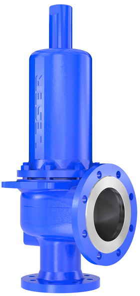
3 Safety Valves Process and General Industrial Safety Valves API meets all requirements of the API 526 norm and includes the entire orifice D to T product range. Series 526 Refineries Chemical industry Petrochemical industry Oil and gas Onshore and Offshore Valve sizes 1" through 8", Orifice D through T Materials: WCB, CF8M, WC6, LCB and in API Alloy Concept materials like Duplex, Super Duplex, Monel, Hastelloy and Inconel with short delivery times Design according to API 526 Great variety of options and flanged connections available Standard metal sealing, soft seat as option Single trim for steam, gas and liquid Type 526 Compact Performance has compact dimensions with a large performance range for its valve size. Series 437, 459 Thermal relief Air/gas compressors and pumps Technical gases and CO 2 plants LPG/LNG terminals, carriers etc. Chemical equipment and piping Cryogenic systems and oxygen applications Great variety of threaded or flanged connections Valve sizes from 3 / 8" through 1 1 / 2" Broad set pressure range up to 800 bar / psig Wide range of materials and options to fit any application Stellited metal sealing for longer product life Soft seat for superior tightness Single trim for steam, gas and liquid Type 437 High Performance Series 441, XXL, 444, 441 Full nozzle, 458 Type 459 is especially used for protecting facilities where maximum discharge capacity needs to be reached quickly. Heat exchanger Chemical equipment and piping General steam installations All industrial applications independent from the medium Air/gas compressors and pumps Great variety of types, materials and options to fit any application Valve sizes from DN 20 through DN 400, 1" through 16" Flange connections according to DIN EN, ANSI/ASME and other High capacity compared to the API requirements Standard metal sealing Single trim for steam, gas and liquid Type 441
4 Safety Valves Specialties Clean Service has the highest aseptic characteristics, has minimum dead space, and allows easy cleanability. Series 48x Type 483 Type 485 Pharmaceutical industry Breweries Food and beverage industry Cosmetic industry Valve sizes DN 25 through DN 100, 1" through 4" Great variety of aseptic connections (e. g. clamps, threads, flanges) and option to fit any application Materials: Stainless steel / 316L, / 316L and special Minimum dead space design and flush-mounting capability Soft seat (FDA compliant elastomers) for superior tightness Gap and crevice free design of internals Elastomer bellows for protection of the hard to clean parts Surface grades according to ASME BPE-2002 and DIN Single trim for steam, gas and liquid Type 484 Critical Service offers solutions for protection from highly corrosive and toxic mediums. Series 447, 546, 449 PTFE-lined Corrosive or aggressive chemicals Chemical equipment and piping Chlorine manufacture and processing Reducing acids (e. g. hydrochloric acid, acetic acid) Alkalis or caustic service MDI systems Valve sizes DN 25 through DN 100, 1" through 4" Flange connections according to DIN EN, ANSI/ASME and other PTFE lining or special materials A PTFE or metal bellows protects the bonnet area against product influences Smooth inside surface avoid adherence of corrosive matters Single trim for steam, gas and liquid Type 447 Modulate Action offers solutions for applications with normal and/or proportional opening characteristics (e.g. thermal expansion). Series 429, 433 Type 429 Thermal expansion Reciprocating compressors and plants with pulsating operating pressure Heat transfer oil systems Protection of liquids Overflow operation Mechanical engineering (OEM) Great variety materials and options to fit any application Valve sizes DN 15 through DN 150, 1 / 2" through 6" Flange connections according to DIN EN, ANSI/ASME and other Low overall height and low weight One connection size for inlet and outlets Single trim for steam, gas and liquid
5 Safety Valves Medium controlled Increase the efficiency of your plant by using Higher operating pressure than is possible with regular spring-loaded safety valves, as High Efficiency safety valves guarantee tightness right until set pressure. Lower media loss during blow-off because High Efficiency safety valves have low opening and reseating pressure differences. Safe operation irrespective of back pressure due to the fact that back pressure has no influence on the opening characteristics of High Efficiency safety valves High Efficiency Pilot Operated Safety Valves are employed especially for conditions where the difference between set pressure and closing pressure is very small and in cases of high back pressure. Series 800 Pilot Operated Safety Valve Oil and gas production, onshore, offshore Refinery (Oil and gas processing) Gas distribution Valve sizes DN 25 through DN 200, 1" through 8", Orifice D through T Materials: , , WCB, LCB, CF8M Full bore for higher capacity based on nominal size. Integrated tubing reduces danger of freezing, damage or leakage Integrated backflow preventer improves versatility of standard model High Efficiency Supplementary loading systems provide optimal tightness right up to set pressure and improved protection for high temperature media and high set pressures. Series 700 Supplementary Loading System Steam producers Paper mills Sugar refineries Adjustable opening and reseating pressure difference for adjustment to plant situation. Decoupling of control system and safety valve, this means that safety valves with supplementary loading can also be used under extreme conditions such as e.g. temperatures above 500 C or contaminated fluids. The triple redundancy of pressure tapping and regulation guarantees the maximum possible reliability. The Series 700 can also be fitted to competitor safety valves to ensure a stable system operation.
6 Safety Valves Additional products and components Change-over valves are used to connect two safety valves to a pressure system. One safety valve is in operation and the other one is on standby. The safety valve on standby can be dismounted and serviced during ongoing operation of the system the protection of the system against excessive pressure remains guaranteed. Best Availability Change-over valves allow uninterrupted plant availability which increases plant productivity. Type 310 XXL Change-over Valve Change-over Valves are used in plants which cannot or should not be switched off such as: Storage tanks for industrial gas Bitumen plants Oil fields Ethylene plants Refineries Uninterrupted operation Simple handling Heavy-duty design The combination of a LESER safety valve and bursting disc combines the advantages of both safety devices. Best Availability A bursting disc safety valve combination meets the highest tightness requirements and ensures controlled operation after a bursting disc bursts. Series 350 Safety Valve Bursting Disc combination The combination of bursting disc and safety valve is the solution for the following applications: Protection of the safety valve from corrosion or coatings. Protection from operating conditions which could impair the functionality of the safety valve. Safeguarding of the process with the highest possible tightness. To prevent a complete media loss after the bursting of the bursting disc. Avoidance of an uncontrolled shut down of a plant after the bursting of the bursting disc. To achieve cost advantages for aggressive media. Conformance to highest tightness requirements. Combination of advantages of safety valve and bursting disc in TUEV certified connection. Controlled operation after bursting of bursting disc
7 LESER GmbH & Co. KG Hamburg, Wendenstr Fon +49 (40) Hamburg, P.O. Box Fax +49 (40) VALVESTAR VALVESTAR The sizing software for safety valves The-Safety-Valve.com VALVESTAR, the sizing program for safety valves developed by LESER, supports all leading worldwide codes and standards. In addition to calculations and sizing the program provides user designed and configurable individual reports for technical documentation and archiving. Program highlights Sizing: Sizing of safety valves according to leading worldwide codes and standards such as: API 520, ASME VIII, ISO 4126, AD 2000-Merkblatt A2 Calculation of two-phase flow in accordance with API 520 Appendix D (Ω-method) and fire case in accordance with API 521 Evaluation of inlet pressure drop, back pressure in pipework, reaction forces as well as noise levels Reports: Settings: Customisable user interface: User specified profile settings with preselection of units, calculation methods etc. More than 15 languages selectable VALVESTAR Web: Online-calculation for safety valves and projects at without any software installation Selectable report types, e.g. project report, single page report Customisable design of report layouts (company logo, address etc.) Range of data export formats, e.g. XLS, RTF, PDF, etc. Integrated material part lists and sectional drawings for all LESER safety valves Design and handling: A user friendly Wizard function leads step-by-step through the calculations Microsoft.Net based architecture offers latest graphical user interface for easy handling and enhanced performance
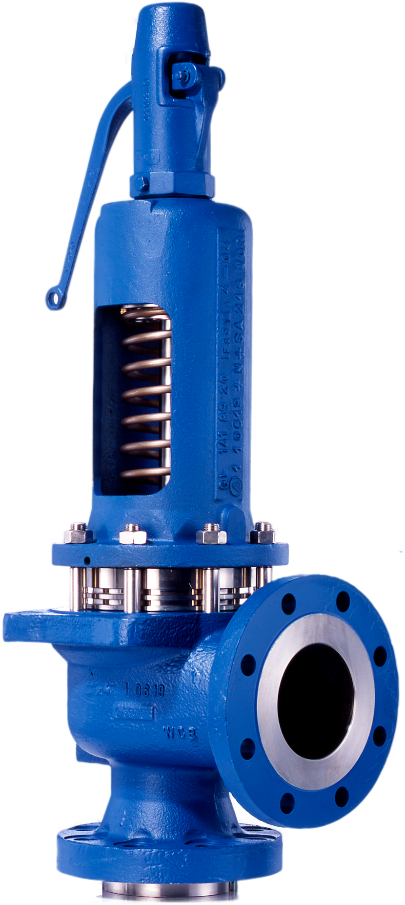
8 Proven Technology Flanged Safety Valves LESER safety valves have been engineered and steadily developed, in close cooperation with plant engineers and service specialists, simplifying design with fewer components for less down time, fewer spare parts and lower maintenance costs. Integral cast support brackets for safe handling of the valves (API and heavy safety valves). One piece spindle allows better alignment. Guiding: Upper and lower guiding with small surface areas help reduce friction, a major cause of galling. Long spring allows large pressure range for each spring thus drastically reducing the overall number of different springs. Single trim for steam, gas and liquids for fewer spare valves in your stock and therefore lower storage costs. Stellited or hardened metal sealing for longer product life. Soft seat solutions for superior tightness O-ring or sealing plate design O-ring Sealing plate LESER defines the set pressure as initial audible discharge (not pop ). This avoids damage to valve seats during set pressure testing and allows for higher shut-off closer to set point. Self-draining body avoids residue build-up and reduces corrosion. API: Full nozzle design Options High Performance: Semi nozzle full bore design LESER s safety valves can be customized with a great variety of options. For further information please refer to Available options of each Type.
9 Proven Technology Compact Performance Safety Valves One piece spindle reduces friction and allows better alignment. Long spring allows large pressure range for each spring thus drastically reducing the overall number of different springs. Single trim for steam, gas and liquids for fewer spare valves in your stock and therefore lower storage costs. Metal seal Stellited or hardened metal sealing for longer product life. Soft seat solutions for superior tightness Two designs: O-ring disc or plastic seat O-ring Sealing plate Threaded or flanged connections for optimized adaption to the plant. Self-draining body avoids residue build-up and reduces corrosion. Male thread Female Thread Flanged version Threaded connections male or female acc. to NPT ANSI/ASME B Threads according to other standards, e.g. ISO, DIN, BSP are also available. Flanged connections acc. to ANSI/ASME B16.5 Flanges acc. to other standards, e.g. ISO, DIN, JIS are also available.
10 The Company LESER GmbH & Co. KG With more than 800 employees, LESER is the largest manufacturer of safety valves in Europe and a leader in its market worldwide. LESER safety valves are developed for the international market at our headquarters in Hamburg and tested on our certified test stand. Production, with a capacity of over 130,000 valves a year, takes place at our modern factory in Hohenwestedt. Eight subsidiaries in Europe, America, the Middle East, and Asia, as well as authorized and trained representatives in over 80 countries guarantee competent consulting for all industrial applications. LESER safety valves protect people and the environment in the chemical, petrochemical, industrial gases, oil and gas production, and machine building branches, as well as the food and pharmaceutical industries. In addition, LESER India produces in India safety valves for the local market. All LESER Safety Valves carry CE and ASME UV Time line 1885 Complete range of steam fittings, incl. safety valves 1957 First test lab for safety valves 1980s Leading supplier for safety valves in Europe 1994 Test lab receives ASME certification (first and only outside of the US) 2003 Launch of the API Series 2008 Expansion of factory in Hohenwestedt 1818 Founded as a brass foundry in Hamburg, Germany 1943 Destruction of the plant, relocation and founding of new factory in Hohenwestedt, Germany 1970s Specialization in safety valves 1990 First ASME approval 1998 First subsidiary founded 2010 Launch of the Pilot Operated Safety Valve
11 Why LESER 7 good reasons to use LESER safety valves 1 Availability LESER is known for short response and short delivery times. This is secured by the factory as well as by the 26 central warehouses worldwide and 66 LESER authorized repair centers (LARCS). Unlike the competitors LESER keeps a high stock of raw material ready. This fact together with a high degree of vertical integration allows quick deliveries within 3 days as well as fast track within 24 hours for all standard safety relief valves. 2 Global Player LESER s sales network is present in all core markets around the world. This enables LESER to act as a local provider, having fundamental knowledge of the local market, the cultural environment and understanding the customers. The local LESER Product Champion is key to this knowledge. LESER offers documentation and catalogs in 15 different languages to assist the customer with the selection and sizing. 3 Product Range LESER s product range includes 9 product groups with altogether 40 safety valve types. This means that LESER s product range offers the right product for almost every application. Multiple options and special materials complete the range as well as client-specific solutions. All safety valves have the necessary certifications for worldwide applications. As a partner LESER offers a complete knowledge in all ranges of possible applications of safety valves and is well established in the PED and the ASME field. 4 Quality LESER s strength is based on advanced advisory skills and support services as well as excellent product and service quality. Modern manufacturing methods, testing facilities for air, liquids and steam (ASME and PED approved), standardized and controlled processes as well as motivated and highly qualified employees ensures LESER a great competitive advantage. LESER s quality management disposes of multiple certifications and supervises all steps of development, engineering and manufacturing. LESER Safety Relief Valves are unique in design and are exclusively manufactured in Germany. The final assembly is mainly carried out locally. A product 100% made in Germany can also be provided. 5 Sustainability LESER looks back on a history of over 190 years and is one of the first manufacturers of safety valves worldwide. The company is family owned for the past 5 generations. 100% of the shares are family-owned. The LESER family reinvests continuously in state-of-theart machinery and raw material stocks to keep ahead on future standards. This trust in LESER and its products is proved by a world -wide installed base of more than 2,000,000 safety valves. 6 Reliability The reliability of LESER and its products is an inherent part of the corporate philosophy. This philosophy is characterized by high compliance with confirmed delivery dates, sustainable actions, highest quality as well as reinvestments of more than 16 Mil. in the past few years in production facilities and the company in general. All safety valve series are thoroughly engineered and routinely undergo exhaustive checks in LESER s own TÜV and ASME-certified test laboratory. This is how LESER can offer a consistently high quality of products and services to the customer. 7 Price A highly automated production in Germany guarantees an attractive cost / performance ratio for safety valves and spares. LESER continuously invests in personnel, machinery and buildings to continue to provide this cost / performance ratio and service quality to its customers.
12 LESER worldwide LESER UK Bristol, United Kingdom LESER Germany Hamburg and Hohenwestedt André Ramseyer AG Flamatt, Switzerland LESER China Tianjin, Beijing, Shanghai and Shenzhen LESER Polska Poznan, Poland LESER France Toulouse LESER USA Charlotte (NC) LESER Brazil Rio de Janeiro LESER Singapore Singapore LESER Bahrain Al Manamah LESER India Mumbai and Paithan LESER stock and local assembly LESER representative LESER at a glance , Edition May 2015 The-Safety-Valve.com LESER GmbH & Co. KG Hamburg, Wendenstr Hamburg, P.O. Box Fon +49 (40) Fax +49 (40) sales@leser.com


 8613371530291