
lever safety valve manufacturer

Searching for tools to control the flow of your piping system? Explore one of the largest featured collections of products and discover a range of wholesale lever safety valve on Alibaba.com. When you search for lever safety valve and related items, you will be able to find many types of lever safety valve varying in size, shape, use, and quality, all at prices in which are highly reasonable!
There are many uses of valves - mainly controlling the flow of fluids and pressure. Some examples include regulating water for irrigation, industrial uses for controlling processes, and residential piping systems. Magnetic valves like those using the solenoid, are often used in a range of industrial processes. Whereas backflow preventers are often used in residential and commercial buildings to ensure the safety and hygiene of the water supplies. Whether you are designing a regulation system for irrigation or merely looking for a new replacement, you will be able to find whatever type of lever safety valve that you need. Our products vary from check valves to pressure reducing valves, ball valves, butterfly valves, thermostatic mixing valves, and a lot more.

Sanitary Manual Air Relief Valve with Lever is generally installed vertically on top of pipes or vessels. Adamant Valves is a global Sanitary Manual Air Relief Valve with Lever manufacturer & supplier, providing customers with high-precision Sanitary Manual Air Relief Valve with Lever at a very affordable price.
There is a wide range of safety valves available to meet the many different applications and performance criteria demanded by different industries. Furthermore, national standards define many varying types of safety valve.
The ASME standard I and ASME standard VIII for boiler and pressure vessel applications and the ASME/ANSI PTC 25.3 standard for safety valves and relief valves provide the following definition. These standards set performance characteristics as well as defining the different types of safety valves that are used:
ASME I valve - A safety relief valve conforming to the requirements of Section I of the ASME pressure vessel code for boiler applications which will open within 3% overpressure and close within 4%. It will usually feature two blowdown rings, and is identified by a National Board ‘V’ stamp.
ASME VIII valve- A safety relief valve conforming to the requirements of Section VIII of the ASME pressure vessel code for pressure vessel applications which will open within 10% overpressure and close within 7%. Identified by a National Board ‘UV’ stamp.
Full bore safety valve - A safety valve having no protrusions in the bore, and wherein the valve lifts to an extent sufficient for the minimum area at any section, at or below the seat, to become the controlling orifice.
Conventional safety relief valve -The spring housing is vented to the discharge side, hence operational characteristics are directly affected by changes in the backpressure to the valve.
Balanced safety relief valve -A balanced valve incorporates a means of minimising the effect of backpressure on the operational characteristics of the valve.
Pilot operated pressure relief valve -The major relieving device is combined with, and is controlled by, a self-actuated auxiliary pressure relief device.
Power-actuated safety relief valve - A pressure relief valve in which the major pressure relieving device is combined with, and controlled by, a device requiring an external source of energy.
Standard safety valve - A valve which, following opening, reaches the degree of lift necessary for the mass flowrate to be discharged within a pressure rise of not more than 10%. (The valve is characterised by a pop type action and is sometimes known as high lift).
Full lift (Vollhub) safety valve -A safety valve which, after commencement of lift, opens rapidly within a 5% pressure rise up to the full lift as limited by the design. The amount of lift up to the rapid opening (proportional range) shall not be more than 20%.
Direct loaded safety valve -A safety valve in which the opening force underneath the valve disc is opposed by a closing force such as a spring or a weight.
Proportional safety valve - A safety valve which opens more or less steadily in relation to the increase in pressure. Sudden opening within a 10% lift range will not occur without pressure increase. Following opening within a pressure of not more than 10%, these safety valves achieve the lift necessary for the mass flow to be discharged.
Diaphragm safety valve -A direct loaded safety valve wherein linear moving and rotating elements and springs are protected against the effects of the fluid by a diaphragm
Bellows safety valve - A direct loaded safety valve wherein sliding and (partially or fully) rotating elements and springs are protected against the effects of the fluids by a bellows. The bellows may be of such a design that it compensates for influences of backpressure.
Controlled safety valve - Consists of a main valve and a control device. It also includes direct acting safety valves with supplementary loading in which, until the set pressure is reached, an additional force increases the closing force.
Safety valve - A safety valve which automatically, without the assistance of any energy other than that of the fluid concerned, discharges a quantity of the fluid so as to prevent a predetermined safe pressure being exceeded, and which is designed to re-close and prevent further flow of fluid after normal pressure conditions of service have been restored. Note; the valve can be characterised either by pop action (rapid opening) or by opening in proportion (not necessarily linear) to the increase in pressure over the set pressure.
Direct loaded safety valve -A safety valve in which the loading due to the fluid pressure underneath the valve disc is opposed only by a direct mechanical loading device such as a weight, lever and weight, or a spring.
Assisted safety valve -A safety valve which by means of a powered assistance mechanism, may additionally be lifted at a pressure lower than the set pressure and will, even in the event of a failure of the assistance mechanism, comply with all the requirements for safety valves given in the standard.
Supplementary loaded safety valve - A safety valve that has, until the pressure at the inlet to the safety valve reaches the set pressure, an additional force, which increases the sealing force.
Note; this additional force (supplementary load), which may be provided by means of an extraneous power source, is reliably released when the pressure at the inlet of the safety valve reaches the set pressure. The amount of supplementary loading is so arranged that if such supplementary loading is not released, the safety valve will attain its certified discharge capacity at a pressure not greater than 1.1 times the maximum allowable pressure of the equipment to be protected.
Pilot operated safety valve -A safety valve, the operation of which is initiated and controlled by the fluid discharged from a pilot valve, which is itself, a direct loaded safety valve subject to the requirement of the standard.
The common characteristic shared between the definitions of conventional safety valves in the different standards, is that their operational characteristics are affected by any backpressure in the discharge system. It is important to note that the total backpressure is generated from two components; superimposed backpressure and the built-up backpressure:
Subsequently, in a conventional safety valve, only the superimposed backpressure will affect the opening characteristic and set value, but the combined backpressure will alter the blowdown characteristic and re-seat value.
The ASME/ANSI standard makes the further classification that conventional valves have a spring housing that is vented to the discharge side of the valve. If the spring housing is vented to the atmosphere, any superimposed backpressure will still affect the operational characteristics. Thiscan be seen from Figure 9.2.1, which shows schematic diagrams of valves whose spring housings are vented to the discharge side of the valve and to the atmosphere.
By considering the forces acting on the disc (with area AD), it can be seen that the required opening force (equivalent to the product of inlet pressure (PV) and the nozzle area (AN)) is the sum of the spring force (FS) and the force due to the backpressure (PB) acting on the top and bottom of the disc. In the case of a spring housing vented to the discharge side of the valve (an ASME conventional safety relief valve, see Figure 9.2.1 (a)), the required opening force is:
In both cases, if a significant superimposed backpressure exists, its effects on the set pressure need to be considered when designing a safety valve system.
Once the valve starts to open, the effects of built-up backpressure also have to be taken into account. For a conventional safety valve with the spring housing vented to the discharge side of the valve, see Figure 9.2.1 (a), the effect of built-up backpressure can be determined by considering Equation 9.2.1 and by noting that once the valve starts to open, the inlet pressure is the sum of the set pressure, PS, and the overpressure, PO.
Balanced safety valves are those that incorporate a means of eliminating the effects of backpressure. There are two basic designs that can be used to achieve this:
Although there are several variations of the piston valve, they generally consist of a piston type disc whose movement is constrained by a vented guide. The area of the top face of the piston, AP, and the nozzle seat area, AN, are designed to be equal. This means that the effective area of both the top and bottom surfaces of the disc exposed to the backpressure are equal, and therefore any additional forces are balanced. In addition, the spring bonnet is vented such that the top face of the piston is subjected to atmospheric pressure, as shown in Figure 9.2.2.
The bellows arrangement prevents backpressure acting on the upper side of the disc within the area of the bellows. The disc area extending beyond the bellows and the opposing disc area are equal, and so the forces acting on the disc are balanced, and the backpressure has little effect on the valve opening pressure.
Bellows failure is an important concern when using a bellows balanced safety valve, as this may affect the set pressure and capacity of the valve. It is important, therefore, that there is some mechanism for detecting any uncharacteristic fluid flow through the bellows vents. In addition, some bellows balanced safety valves include an auxiliary piston that is used to overcome the effects of backpressure in the case of bellows failure. This type of safety valve is usually only used on critical applications in the oil and petrochemical industries.
Since balanced pressure relief valves are typically more expensive than their unbalanced counterparts, they are commonly only used where high pressure manifolds are unavoidable, or in critical applications where a very precise set pressure or blowdown is required.
This type of safety valve uses the flowing medium itself, through a pilot valve, to apply the closing force on the safety valve disc. The pilot valve is itself a small safety valve.
The diaphragm type is typically only available for low pressure applications and it produces a proportional type action, characteristic of relief valves used in liquid systems. They are therefore of little use in steam systems, consequently, they will not be considered in this text.
The piston type valve consists of a main valve, which uses a piston shaped closing device (or obturator), and an external pilot valve. Figure 9.2.4 shows a diagram of a typical piston type, pilot operated safety valve.
The piston and seating arrangement incorporated in the main valve is designed so that the bottom area of the piston, exposed to the inlet fluid, is less than the area of the top of the piston. As both ends of the piston are exposed to the fluid at the same pressure, this means that under normal system operating conditions, the closing force, resulting from the larger top area, is greater than the inlet force. The resultant downward force therefore holds the piston firmly on its seat.
If the inlet pressure were to rise, the net closing force on the piston also increases, ensuring that a tight shut-off is continually maintained. However, when the inlet pressure reaches the set pressure, the pilot valve will pop open to release the fluid pressure above the piston. With much less fluid pressure acting on the upper surface of the piston, the inlet pressure generates a net upwards force and the piston will leave its seat. This causes the main valve to pop open, allowing the process fluid to be discharged.
When the inlet pressure has been sufficiently reduced, the pilot valve will reclose, preventing the further release of fluid from the top of the piston, thereby re-establishing the net downward force, and causing the piston to reseat.
Pilot operated safety valves offer good overpressure and blowdown performance (a blowdown of 2% is attainable). For this reason, they are used where a narrow margin is required between the set pressure and the system operating pressure. Pilot operated valves are also available in much larger sizes, making them the preferred type of safety valve for larger capacities.
One of the main concerns with pilot operated safety valves is that the small bore, pilot connecting pipes are susceptible to blockage by foreign matter, or due to the collection of condensate in these pipes. This can lead to the failure of the valve, either in the open or closed position, depending on where the blockage occurs.
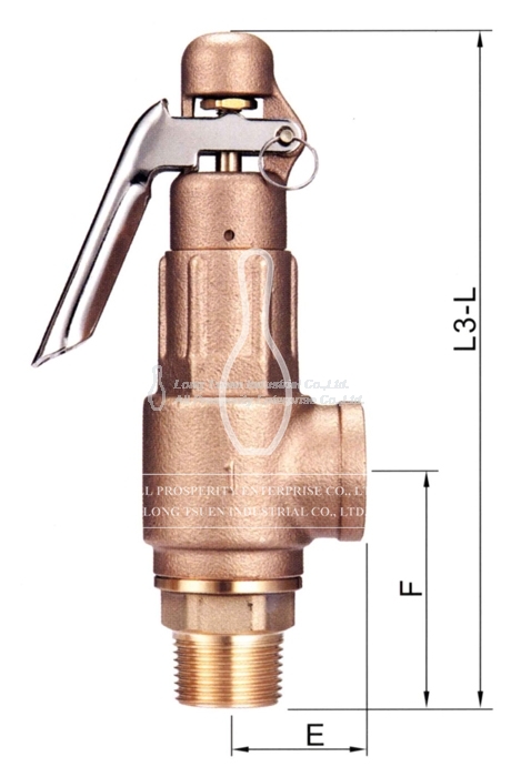
The terms full lift, high lift and low lift refer to the amount of travel the disc undergoes as it moves from its closed position to the position required to produce the certified discharge capacity, and how this affects the discharge capacity of the valve.
A full lift safety valve is one in which the disc lifts sufficiently, so that the curtain area no longer influences the discharge area. The discharge area, and therefore the capacity of the valve are subsequently determined by the bore area. This occurs when the disc lifts a distance of at least a quarter of the bore diameter. A full lift conventional safety valve is often the best choice for general steam applications.
The disc of a high lift safety valve lifts a distance of at least 1/12th of the bore diameter. This means that the curtain area, and ultimately the position of the disc, determines the discharge area. The discharge capacities of high lift valves tend to be significantly lower than those of full lift valves, and for a given discharge capacity, it is usually possible to select a full lift valve that has a nominal size several times smaller than a corresponding high lift valve, which usually incurs cost advantages.Furthermore, high lift valves tend to be used on compressible fluids where their action is more proportional.
In low lift valves, the disc only lifts a distance of 1/24th of the bore diameter. The discharge area is determined entirely by the position of the disc, and since the disc only lifts a small amount, the capacities tend to be much lower than those of full or high lift valves.
Except when safety valves are discharging, the only parts that are wetted by the process fluid are the inlet tract (nozzle) and the disc. Since safety valves operate infrequently under normal conditions, all other components can be manufactured from standard materials for most applications. There are however several exceptions, in which case, special materials have to be used, these include:
Cast steel -Commonly used on higher pressure valves (up to 40 bar g). Process type valves are usually made from a cast steel body with an austenitic full nozzle type construction.
For all safety valves, it is important that moving parts, particularly the spindle and guides are made from materials that will not easily degrade or corrode. As seats and discs are constantly in contact with the process fluid, they must be able to resist the effects of erosion and corrosion.
The spring is a critical element of the safety valve and must provide reliable performance within the required parameters. Standard safety valves will typically use carbon steel for moderate temperatures. Tungsten steel is used for higher temperature, non-corrosive applications, and stainless steel is used for corrosive or clean steam duty. For sour gas and high temperature applications, often special materials such as monel, hastelloy and ‘inconel’ are used.
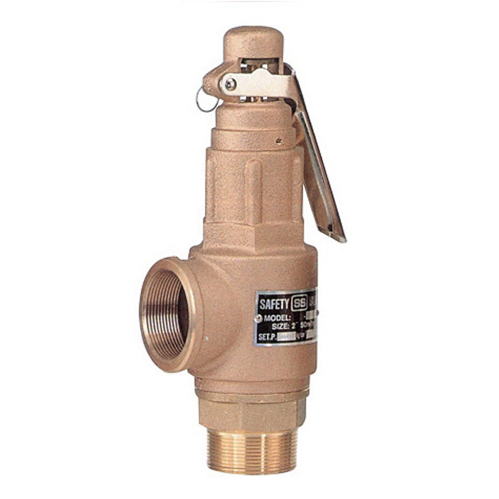
Standard safety valves are generally fitted with an easing lever, which enables the valve to be lifted manually in order to ensure that it is operational at pressures in excess of 75% of set pressure. This is usually done as part of routine safety checks, or during maintenance to prevent seizing. The fitting of a lever is usually a requirement of national standards and insurance companies for steam and hot water applications. For example, the ASME Boiler and Pressure Vessel Code states that pressure relief valves must be fitted with a lever if they are to be used on air, water over 60°C, and steam.
A standard or open lever is the simplest type of lever available. It is typically used on applications where a small amount of leakage of the fluid to the atmosphere is acceptable, such as on steam and air systems, (see Figure 9.2.5 (a)).
Where it is not acceptable for the media to escape, a packed lever must be used. This uses a packed gland seal to ensure that the fluid is contained within the cap, (see Figure 9.2.5 (b)).
For service where a lever is not required, a cap can be used to simply protect the adjustment screw. If used in conjunction with a gasket, it can be used to prevent emissions to the atmosphere, (see Figure 9.2.6).
A test gag (Figure 9.2.7) may be used to prevent the valve from opening at the set pressure during hydraulic testing when commissioning a system. Once tested, the gag screw is removed and replaced with a short blanking plug before the valve is placed in service.
The amount of fluid depends on the particular design of safety valve. If emission of this fluid into the atmosphere is acceptable, the spring housing may be vented to the atmosphere – an open bonnet. This is usually advantageous when the safety valve is used on high temperature fluids or for boiler applications as, otherwise, high temperatures can relax the spring, altering the set pressure of the valve. However, using an open bonnet exposes the valve spring and internals to environmental conditions, which can lead to damage and corrosion of the spring.
When the fluid must be completely contained by the safety valve (and the discharge system), it is necessary to use a closed bonnet, which is not vented to the atmosphere. This type of spring enclosure is almost universally used for small screwed valves and, it is becoming increasingly common on many valve ranges since, particularly on steam, discharge of the fluid could be hazardous to personnel.
Some safety valves, most commonly those used for water applications, incorporate a flexible diaphragm or bellows to isolate the safety valve spring and upper chamber from the process fluid, (see Figure 9.2.9).

We"ve numerous great employees customers excellent at promoting, QC, and working with kinds of troublesome difficulty inside the generation method for Spring Loaded Full Bore Type With Lever Safety Valve, Wafer Butterfly Valve, Closed Spring Loaded Low Lift Type High Pressure Safety Valve, Pressure Limiting Valve,Cdl(F)Vertical Multistage Centrifugal Pump. Never-ending improvement and striving for 0% deficiency are our two main excellent policies. Should you need anything, never be reluctant to speak to us. The product will supply to all over the world, such as Europe, America, Australia,Turkey, Bangkok,India, Panama.With many years good service and development, we have a qualified international trade sales team. Our goods have exported to North America, Europe, Japan, Korea, Australia, New Zealand, Russia and other countries. Looking forward to build up a good and long term cooperation with you in coming future!
We rely upon strategic thinking, constant modernisation in all segments, technological advances and of course upon our employees that directly participate in our success for Single-Lever Safety Valve, Awwa C515 Out Screw and Yoke Resilient Seated Gate Valve, Safety Valve, Y Type Strainer,Orbit Ball Valve. Since establishment in the early 1990s, we have set up our sale network in USA, Germany, Asia, and several Middle Eastern countries. We aim to be a top class supplier for worldwide OEM and aftermarket! The product will supply to all over the world, such as Europe, America, Australia,Montreal, venezuela,Danish, Madagascar.Our company is working by the operation principle of "integrity-based, cooperation created, people oriented, win-win cooperation". We hope we can have a friendly relationship with businessman from all over the world.
Because a safety valve is often the last device to prevent catastrophic failure under pressure conditions, it is important that the valve works at all times i.e. it must be 100% reliable.
Safety valves should be installed wherever the maximum allowable working pressure of a system or pressure containing vessel is likely to be exceeded, in particular under fault conditions due to the failure of another piece of equipment in the system.
The term “Safety Valve” and “Relief Valve” are generic terms to describe a variety of pressure relief devices. A wide range is available based on the application and required performance criteria. The different designs are required to meet numerous national standards.
The images below show the devastating results of a failed Safety valve (due to poor maintenace) or ones which have been incorrectly sized, installed or maintained.
A spring-loaded pressure relief valve which is designed to open to relieve excess pressure and to reclose and prevent the further flow of fluid after normal conditions have been restored. It is characterised by a rapid-opening "pop" action or by opening in a manner generally proportional to the increase in pressure over the opening pressure. It may be used for either compressible or incompressible fluids, depending on design, adjustment, or application.
Relief valve - A pressure relief device actuated by inlet static pressure having a gradual lift generally proportional to the increase in pressure over opening pressure.
Safety relief valve - A pressure relief valve characterised by rapid opening or pop action, or by opening in proportion to the increase in pressure over the opening pressure, depending on the application, and which may be used either for liquid or compressible fluid.
Safety valve - A valve which automatically, without the assistance of any energy other than that of the fluid concerned, discharges a quantity of the fluid so as to prevent a predetermined safe pressure being exceeded, and which is designed to re-close and prevent further flow of fluid after normal pressure conditions of service have been restored.
The images below show a standard Relief valve and a standard Safety valve from a well-known UK manufacturer. Each manufacturer does things slightly differently however all of the basic components and principles of operation are the same. As described previously, a safety valve differs from a relief valve in that it opens rapidly once the set pressure has been reached. For the same inlet size and with the valve in the closed position, the surface area that the pressure on the inlet side will see is the same. When the set pressure is reached and the valve starts to open, the disk on a Safety valve is larger (see the diagrams below) and hence the same pressure then sees a much larger surface area and consequently the force increases greatly causing the valve to open quickly and hence the characteristic pop action.
The image below shows the above Safety valves and Relief valves dismantled. The disk diameter on the 1" (DN25) Safety valve is only 7mm larger than on the Relief valve which doesnt sound like much, but when you calculate the areas it is an increase of 36%.
This diagram represents a Safety valve in its very simplest form. The force acting on the inlet side of the disk is acting against the force applied by the spring plus the force applied by the back pressure on the top of the disk.
The valve remains closed when(PI x Ab) < Fs + (PB x At), is in equilibrium when(PI x Ab) = Fs + (PB x At) and opens when(PI x Ab) > Fs + (PB x At) were PI = Inlet pressure, PB = Back pressure, At = Top of disk area, Ab = Bottom of disk area. Things to notice from this design are that if PB is variable and quite large relative to PI, then this will cause the pressure at which the valve opens to vary which is undesirable. The following two designs (Fig 3 & Fig 4) are available that eliminate the effect of back pressure on the set pressure.
The bellows prevents backpressure acting on the top side of the disk. In relation to the piston there is no top side within the main body of the valve hence again the back pressure cannot affect the set pressure. Bellows failure is an important concern in critical applications where a very precise set pressure is required. In these cases some mechanism to detect a leak of process medium out of the top vent would be implemented. Piston designs are not usually found in conventional Safety valves but are more common in Pilot Operated Safety valves.
API 520 Practice Guidelines: a conventional design should not typically be used when the built-up backpressure is greater than 10% of the set pressure at 10% over pressure. European standard EN ISO 4126: the built-up backpressure should be limited to 10% of the set pressure when the valve is discharging at the certified capacity.
Overpressure is the percentage over the set pressure by which the valve is fully open. The blowdown is the percentage below the set pressure by which the valve is fully closed.
The basic elements of the design are right angle pattern valve body, inlet can be either a full nozzle or a semi-nozzle type. With a full nozzle design has the “wetted” inlet tract formed from one piece (as per figure 6) with the seat integrated into the top of the nozzle. The internal bore of the nozzle and the disc is the only part of the valve that is exposed to the process fluid with the valve in the closed position. A semi-nozzle design consists of a seating ring fitted into the body.The disc is held onto the seat by the stem, with the downward force coming from the compression on the spring mounted in the bonnet. The amount of compression on the spring is adjusted by the spring adjuster under the cap.
Unless bellows or diaphragm sealing is used, process fluid will enter the spring housing (or bonnet). The amount of fluid depends on the particular design of safety valve. If emission of this fluid into the atmosphere is acceptable, the spring housing may be vented to the atmosphere - an open bonnet. This is usually advantageous when the safety valve is used on high temperature fluids or for boiler applications as, otherwise, high temperatures can relax the spring, altering the set pressure of the valve. However, using an open bonnet exposes the valve spring and internals to environmental conditions, which can lead to damage and corrosion of the spring.
When the fluid must be completely contained by the safety valve (and the discharge system), it is necessary to use a closed bonnet, which is not vented to the atmosphere. This type of spring enclosure is almost universally used for small screwed valves and, it is becoming increasingly common on many valve ranges since, particularly on steam, discharge of the fluid could be hazardous to personnel.
A lifting mechanism is recommended to test for correct valve operation at all times where corrosion, caking, or any deposit could prevent the opening operation.
Foreign particles can lodge under the seat of the valve when it discharges. The lifting lever allows you to lift the valve and flush the obstruction. Pressure relief valves for Section VIII require a lift lever on all air, steam, and hot water valves used at temperatures over 60 degC. Typically used where periodic testing of the valve in location is desired to assure its operation. With an Open lifting lever design, when the valve discharges, fluid media will escape into the atmosphere around the open lifting lever assembly. If this is not desirable or when back pressure is present you would select a Packed Lifting Lever design.
As described above, this type is selected where leakage of the media to the atmosphere during valve discharge or during back pressure would be un-desirable. A packed lever design is a completely sealed assembly.
Under certain circumstances i.e. under the start-up conditions of a plant or to pressure test the system in a controlled environment, it may be required that the valve is prevented from opening.This is achieved by screwing the bolt (shown on the wire) into the cap which screws down onto the stem and prevents it lifting. Obviously it is important that test gags are removed prior to placing the valve into service.
The bellows is designed to cover the same area on the back of the disc equal to the seat area hence the back pressure will have no effect on the set pressure. See the previous section “Basic Safety Valve Principles”. Bellows also protects the spindle, spindle guide and spring from the process medium.
A disc is held against the nozzle by a spring, which is contained in a cast bonnet. The spring is adjusted by a compression screw to permit the calibration of opening or set pressure. An adjustable nozzle ring, threaded onto the nozzle, controls the geometry of the fluid exit control chamber (also known as a huddling chamber). The control chamber (huddling chamber) geometry is very important in controlling valve opening and closing pressures and stability of operation. The nozzle ring is locked into position by a ring pin assembly as shown in Figure 15 below.
Under normal system operation the valve remains in the closed position because the spring force (Fs) is greater than the system pressure acting on the internal nozzle seating area (PA). If system pressure increases to a point when these forces are equal, then the set pressure is reached. The disc lifts and fluid flows through the valve. When pressure in the system returns to a safe level, the valve closes.
Just prior to reaching set point, the pressure relief valve leaks system fluid into the huddling chamber. The fluid now acts on a larger area of the disc inside the huddling chamber (PAh), causing the valve to experience an instantaneous increase in the opening force. Refer to the figure 16 above to see relationship between Nozzle Area (A) and the Huddling Chamber Area (Ah). System pressure acting on the larger area will suddenly open the safety relief valve at a rapid rate.
Although the opening is rapid and dramatic, the valve does not open fully at set point. The system pressure must increase above set point to open the valve to its full lift and capacity position. Maximum lift and certified flow rates will be achieved within the allowable limits (overpressure) established by various codes and standards. All pressure relief ales are allowed an overpressure allowance to reach full rated flow. The allowable over pressure can vary from 10% to 21% on unfired vessels and systems, depending on the sizing basis, number of valves, and whether a fire condition is encountered.
Once the valve has controlled the pressure excursion, system pressure will start to reduce. Since the huddling chamber area is now controlling the exit fluid flow, system pressure must reduce below the set point before the spring force is able to close the valve. The difference between the set pressure and the closing pressure is called blowdown, and is usually expressed as a percentage of set pressure. The typical blowdown can vary from 7% to 10%, the industry standard.
The nozzle ring adjustment changes the shape and volume of the huddling chamber, and its position will affect both the opening and the closing characteristics of the valve. When the nozzle ring is adjusted to its top position, the huddling chamber is restricted to its maximum. The valve will usually pop very distinctly with a minimum simmer (leakage before opening), but the blowdown will increase. When the nozzle ring is lowered to its lowest position, minimal restriction to the huddling chamber occurs. At this position, simmer increases and the blowdown decreases. The final ring position is somewhere between these two extremes to provide optimal performance.
On liquid service, a different dynamic situation exists. Liquids do not expand when flowing across orifices, and a small amount of fluid flow across the nozzle will produces a large local pressure drop at the nozzle orifice. This local pressure drop causes the spring to reclose the valve if the fluid flow is minimal. Liquids leaking into the huddling chamber can quickly drain out by gravity and prevent fluid pressure from building up in the secondary area of the huddling chamber. Liquid relief valves are thus susceptible to a phenomenon called chatter, especially at low fluid flow rates. Chatter is the rapid opening and closing of the pressure relief valve and is always destructive.
Because of the difference in the characteristics of gases and liquids, some valve designs require a special liquid trim in order to meet ASME Code Section VIII performance criteria of full rated liquid flow at 10% overpressure. With liquids since no visible or audible pop is heard at set point, the set pressure is defined as the pressure when the first heavy flow occurs (a pencil sized steady stream of water that remains unbroken for approximately one inch).
Manufacturers usually state their recommended testing procedure and testing intervals in their Installation, Operating and Maintenance Instructions (IOM). Typically, they recommend a manual test every 3 or 6 months (assuming it has a lifting lever) and a set pressure test every 12 months. It is sensible to incorporate these into your maintenance plan so they are not missed. Sometimes your insurance company may require them to be tested even more regularly than this i.e. every 6 months. Testing in most cases involves removing them from your system and having them recertified in an approved workshop.
If you have a system that is shut down for annual maintenance then this is an ideal time to remove your Safety valves and have them inspected and recertified.
For systems that can only be off for short periods of time, it is sensible to keep a spare valve to swap over and then the removed valve can be inspected and recertified.
For systems that cannot be shut down, you will need to use a changeover valve which allows you to swap between Safety valves allowing one to be removed for inspection and testing.
For larger Safety valves on systems that run continuously, you may consider using in-situ testing. This method does have some limitations however since you cannot visually inspect the inside of the valve, but it will tell you if the valve is opening at the correct set pressure.
(a) A valve passing (leaking) on the outlet side when the valve is supposed to be closed. This can happen to valves of any age (new or old) and occurs if debris contained in the medium passes through the valve at a point when the valve lifts, and the debris either traps or damages the internals of the valve. On soft seated valves, hard particles may embed themselves in the soft material causing re-sealing issues. If your valve has a lifting lever and it is safe to do so, then it is worth lifting the handle for a few seconds which will hopefully clear any debris allowing the valve to reseal correctly. If this isn’t an option or it doesn’t cure the problem, then the valve will need to be removed and returned for maintenance and recertification. The time we often see this the most is during the startup of a system and there is a pressure spike, hence this is why it is extremely important that a system is flushed out well before hand.
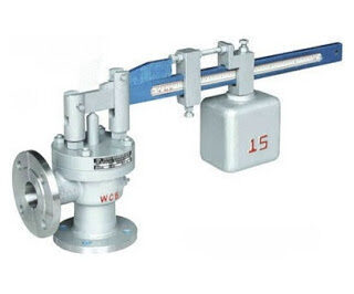
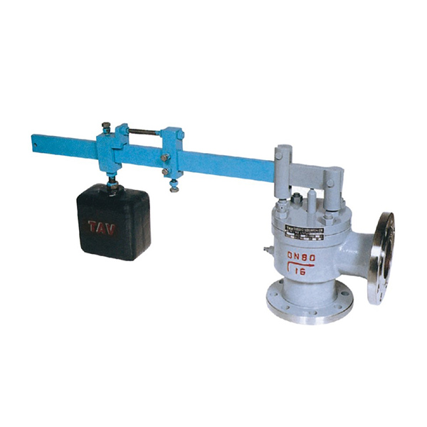
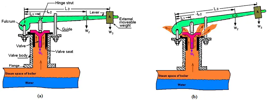
A lever safety valve consists of a valve body that has flange fixed to the steam boiler. The valve seat made of bronze is screwed to the body. The valve seat contains the valve which is also made up of bronze. Since the valve seat and valve is made up of same material, the rusting is prevented. The strut transmits the thrust on the valve. One end of the lever is fixed as fulcrum. The other end is attached to the load. A guide is also provided to move the lever vertically.
In lever safety valve, during the normal pressure inside the boiler, the valve remains in the seat. The thrust applied by the strut made the valve to stay in the seat until the steam pressure exceeds the safe working pressure.
As the steam pressure inside the boiler exceeds the safe working pressure, the valve rises above the seat and steam blows off outside the boiler. The valve returns back to its normal position when the pressure inside the boiler falls back to its normal pressure.
The valve rises in the condition when the steam pressure force becomes greater than the thrust applied by the strut on the valve. The thrust on the valve can be varied by varying the load attached at one end of the lever.
Here you have learned about lever safety valve, its main parts, working, and where it is used. If you found this piece of information useful then don’t forget to like and share.

A safety valve is a valve that acts as a fail-safe. An example of safety valve is a pressure relief valve (PRV), which automatically releases a substance from a boiler, pressure vessel, or other system, when the pressure or temperature exceeds preset limits. Pilot-operated relief valves are a specialized type of pressure safety valve. A leak tight, lower cost, single emergency use option would be a rupture disk.
Safety valves were first developed for use on steam boilers during the Industrial Revolution. Early boilers operating without them were prone to explosion unless carefully operated.
Vacuum safety valves (or combined pressure/vacuum safety valves) are used to prevent a tank from collapsing while it is being emptied, or when cold rinse water is used after hot CIP (clean-in-place) or SIP (sterilization-in-place) procedures. When sizing a vacuum safety valve, the calculation method is not defined in any norm, particularly in the hot CIP / cold water scenario, but some manufacturers
The earliest and simplest safety valve was used on a 1679 steam digester and utilized a weight to retain the steam pressure (this design is still commonly used on pressure cookers); however, these were easily tampered with or accidentally released. On the Stockton and Darlington Railway, the safety valve tended to go off when the engine hit a bump in the track. A valve less sensitive to sudden accelerations used a spring to contain the steam pressure, but these (based on a Salter spring balance) could still be screwed down to increase the pressure beyond design limits. This dangerous practice was sometimes used to marginally increase the performance of a steam engine. In 1856, John Ramsbottom invented a tamper-proof spring safety valve that became universal on railways. The Ramsbottom valve consisted of two plug-type valves connected to each other by a spring-laden pivoting arm, with one valve element on either side of the pivot. Any adjustment made to one of valves in an attempt to increase its operating pressure would cause the other valve to be lifted off its seat, regardless of how the adjustment was attempted. The pivot point on the arm was not symmetrically between the valves, so any tightening of the spring would cause one of the valves to lift. Only by removing and disassembling the entire valve assembly could its operating pressure be adjusted, making impromptu "tying down" of the valve by locomotive crews in search of more power impossible. The pivoting arm was commonly extended into a handle shape and fed back into the locomotive cab, allowing crews to "rock" both valves off their seats to confirm they were set and operating correctly.
Safety valves also evolved to protect equipment such as pressure vessels (fired or not) and heat exchangers. The term safety valve should be limited to compressible fluid applications (gas, vapour, or steam).
For liquid-packed vessels, thermal relief valves are generally characterized by the relatively small size of the valve necessary to provide protection from excess pressure caused by thermal expansion. In this case a small valve is adequate because most liquids are nearly incompressible, and so a relatively small amount of fluid discharged through the relief valve will produce a substantial reduction in pressure.
Flow protection is characterized by safety valves that are considerably larger than those mounted for thermal protection. They are generally sized for use in situations where significant quantities of gas or high volumes of liquid must be quickly discharged in order to protect the integrity of the vessel or pipeline. This protection can alternatively be achieved by installing a high integrity pressure protection system (HIPPS).
In the petroleum refining, petrochemical, chemical manufacturing, natural gas processing, power generation, food, drinks, cosmetics and pharmaceuticals industries, the term safety valve is associated with the terms pressure relief valve (PRV), pressure safety valve (PSV) and relief valve.
The generic term is Pressure relief valve (PRV) or pressure safety valve (PSV). PRVs and PSVs are not the same thing, despite what many people think; the difference is that PSVs have a manual lever to open the valve in case of emergency.
Relief valve (RV): an automatic system that is actuated by the static pressure in a liquid-filled vessel. It specifically opens proportionally with increasing pressure
Pilot-operated safety relief valve (POSRV): an automatic system that relieves on remote command from a pilot, to which the static pressure (from equipment to protect) is connected
Low pressure safety valve (LPSV): an automatic system that relieves static pressure on a gas. Used when the difference between the vessel pressure and the ambient atmospheric pressure is small.
Vacuum pressure safety valve (VPSV): an automatic system that relieves static pressure on a gas. Used when the pressure difference between the vessel pressure and the ambient pressure is small, negative and near to atmospheric pressure.
Low and vacuum pressure safety valve (LVPSV): an automatic system that relieves static pressure on a gas. Used when the pressure difference is small, negative or positive and near to atmospheric pressure.
In most countries, industries are legally required to protect pressure vessels and other equipment by using relief valves. Also, in most countries, equipment design codes such as those provided by the ASME, API and other organizations like ISO (ISO 4126) must be complied with. These codes include design standards for relief valves and schedules for periodic inspection and testing after valves have been removed by the company engineer.
Today, the food, drinks, cosmetics, pharmaceuticals and fine chemicals industries call for hygienic safety valves, fully drainable and Cleanable-In-Place. Most are made of stainless steel; the hygienic norms are mainly 3A in the USA and EHEDG in Europe.
The first safety valve was invented by Denis Papin for his steam digester, an early pressure cooker rather than an engine.steelyard" lever a smaller weight was required, also the pressure could easily be regulated by sliding the same weight back and forth along the lever arm. Papin retained the same design for his 1707 steam pump.Greenwich in 1803, one of Trevithick"s high-pressure stationary engines exploded when the boy trained to operate the engine left it to catch eels in the river, without first releasing the safety valve from its working load.
Although the lever safety valve was convenient, it was too sensitive to the motion of a steam locomotive. Early steam locomotives therefore used a simpler arrangement of weights stacked directly upon the valve. This required a smaller valve area, so as to keep the weight manageable, which sometimes proved inadequate to vent the pressure of an unattended boiler, leading to explosions. An even greater hazard was the ease with which such a valve could be tied down, so as to increase the pressure and thus power of the engine, at further risk of explosion.
Although deadweight safety valves had a short lifetime on steam locomotives, they remained in use on stationary boilers for as long as steam power remained.
Weighted valves were sensitive to bouncing from the rough riding of early locomotives. One solution was to use a lightweight spring rather than a weight. This was the invention of Timothy Hackworth on his leaf springs.
These direct-acting spring valves could be adjusted by tightening the nuts retaining the spring. To avoid tampering, they were often shrouded in tall brass casings which also vented the steam away from the locomotive crew.
The Salter coil spring spring balance for weighing, was first made in Britain by around 1770.spring steels to make a powerful but compact spring in one piece. Once again by using the lever mechanism, such a spring balance could be applied to the considerable force of a boiler safety valve.
The spring balance valve also acted as a pressure gauge. This was useful as previous pressure gauges were unwieldy mercury manometers and the Bourdon gauge had yet to be invented.
Paired valves were often adjusted to slightly different pressures too, a small valve as a control measure and the lockable valve made larger and permanently set to a higher pressure, as a safeguard.Sinclair for the Eastern Counties Railway in 1859, had the valve spring with pressure scale behind the dome, facing the cab, and the locked valve ahead of the dome, out of reach of interference.
In 1855, John Ramsbottom, later locomotive superintendent of the LNWR, described a new form of safety valve intended to improve reliability and especially to be tamper-resistant. A pair of plug valves were used, held down by a common spring-loaded lever between them with a single central spring. This lever was characteristically extended rearwards, often reaching into the cab on early locomotives. Rather than discouraging the use of the spring lever by the fireman, Ramsbottom"s valve encouraged this. Rocking the lever freed up the valves alternately and checked that neither was sticking in its seat.
A drawback to the Ramsbottom type was its complexity. Poor maintenance or mis-assembly of the linkage between the spring and the valves could lead to a valve that no longer opened correctly under pressure. The valves could be held against their seats and fail to open or, even worse, to allow the valve to open but insufficiently to vent steam at an adequate rate and so not being an obvious and noticeable fault.Rhymney Railway, even though the boiler was almost new, at only eight months old.
Naylor valves were introduced around 1866. A bellcrank arrangement reduced the strain (percentage extension) of the spring, thus maintaining a more constant force.L&Y & NER.
All of the preceding safety valve designs opened gradually and had a tendency to leak a "feather" of steam as they approached "blowing-off", even though this was below the pressure. When they opened they also did so partially at first and didn"t vent steam quickly until the boiler was well over pressure.
The quick-opening "pop" valve was a solution to this. Their construction was simple: the existing circular plug valve was changed to an inverted "top hat" shape, with an enlarged upper diameter. They fitted into a stepped seat of two matching diameters. When closed, the steam pressure acted only on the crown of the top hat, and was balanced by the spring force. Once the valve opened a little, steam could pass the lower seat and began to act on the larger brim. This greater area overwhelmed the spring force and the valve flew completely open with a "pop". Escaping steam on this larger diameter also held the valve open until pressure had dropped below that at which it originally opened, providing hysteresis.
These valves coincided with a change in firing behaviour. Rather than demonstrating their virility by always showing a feather at the valve, firemen now tried to avoid noisy blowing off, especially around stations or under the large roof of a major station. This was mostly at the behest of stationmasters, but firemen also realised that any blowing off through a pop valve wasted several pounds of boiler pressure; estimated at 20 psi lost and 16 lbs or more of shovelled coal.
Pop valves derived from Adams"s patent design of 1873, with an extended lip. R. L. Ross"s valves were patented in 1902 and 1904. They were more popular in America at first, but widespread from the 1920s on.
Although showy polished brass covers over safety valves had been a feature of steam locomotives since Stephenson"s day, the only railway to maintain this tradition into the era of pop valves was the GWR, with their distinctive tapered brass safety valve bonnets and copper-capped chimneys.
Developments in high-pressure water-tube boilers for marine use placed more demands on safety valves. Valves of greater capacity were required, to vent safely the high steam-generating capacity of these large boilers.Naylor valve) became more critical.distilled feedwater and also a scouring of the valve seats, leading to wear.
High-lift safety valves are direct-loaded spring types, although the spring does not bear directly on the valve, but on a guide-rod valve stem. The valve is beneath the base of the stem, the spring rests on a flange some height above this. The increased space between the valve itself and the spring seat allows the valve to lift higher, further clear of the seat. This gives a steam flow through the valve equivalent to a valve one and a half or twice as large (depending on detail design).
The Cockburn Improved High Lift design has similar features to the Ross pop type. The exhaust steam is partially trapped on its way out and acts on the base of the spring seat, increasing the lift force on the valve and holding the valve further open.
To optimise the flow through a given diameter of valve, the full-bore design is used. This has a servo action, where steam through a narrow control passage is allowed through if it passes a small control valve. This steam is then not exhausted, but is passed to a piston that is used to open the main valve.
There are safety valves known as PSV"s and can be connected to pressure gauges (usually with a 1/2" BSP fitting). These allow a resistance of pressure to be applied to limit the pressure forced on the gauge tube, resulting in prevention of over pressurisation. the matter that has been injected into the gauge, if over pressurised, will be diverted through a pipe in the safety valve, and shall be driven away from the gauge.
There is a wide range of safety valves having many different applications and performance criteria in different areas. In addition, national standards are set for many kinds of safety valves.
Safety valves are required on water heaters, where they prevent disaster in certain configurations in the event that a thermostat should fail. Such a valve is sometimes referred to as a "T&P valve" (Temperature and Pressure valve). There are still occasional, spectacular failures of older water heaters that lack this equipment. Houses can be leveled by the force of the blast.
Pressure cookers usually have two safety valves to prevent explosions. On older designs, one is a nozzle upon which a weight sits. The other is a sealed rubber grommet which is ejected in a controlled explosion if the first valve gets blocked. On newer generation pressure cookers, if the steam vent gets blocked, a safety spring will eject excess pressure and if that fails, the gasket will expand and release excess pressure downwards between the lid and the pan. Also, newer generation pressure cookers have a safety interlock which locks the lid when internal pressure exceeds atmospheric pressure, to prevent accidents from a sudden release of very hot steam, food and liquid, which would happen if the lid were to be removed when the pan is still slightly pressurised inside (however, the lid will be very hard or impossible to open when the pot is still pressurised).
La Pavoni Lever Safety Valve Gold Brass body code 396738 is used to replace problematic valves, which usually leads to no pressure buildup and strange sounds during heat up.

Distributor of hydraulic press safety, quick opening safety, rotary and safety valves. Amerigear®, Boston Gear®, Carlisle®, DeMag®, Desch® and IMI Norgren®, pneumatic, double action, quick release and flow control valves also provided. Repair and preventative maintenance services are offered. Value added services such as custom barcoding, CAD capabilities, OEM assembly, plant surveys and third party logistics are also available. Serves the metal processing, metal service center, paper mill and paper converting, canning, grinding, commercial laundry, marine, oil and gas and material handling industries. Vendor managed inventory (VMI) programs available. Kanban delivery.


 8613371530291