
lpg gas safety valve free sample
Searching for tools to control the flow of your piping system? Explore one of the largest featured collections of products and discover a range of wholesale lpg gas safety valve on Alibaba.com. When you search for lpg gas safety valve and related items, you will be able to find many types of lpg gas safety valve varying in size, shape, use, and quality, all at prices in which are highly reasonable!
There are many uses of valves - mainly controlling the flow of fluids and pressure. Some examples include regulating water for irrigation, industrial uses for controlling processes, and residential piping systems. Magnetic valves like those using the solenoid, are often used in a range of industrial processes. Whereas backflow preventers are often used in residential and commercial buildings to ensure the safety and hygiene of the water supplies. Whether you are designing a regulation system for irrigation or merely looking for a new replacement, you will be able to find whatever type of lpg gas safety valve that you need. Our products vary from check valves to pressure reducing valves, ball valves, butterfly valves, thermostatic mixing valves, and a lot more.

Mechatest delivers operator safety and friendly LPG sampling systems that allows for sampling in a safe and controlled environment. To take under high pressure LPG samples the conventional
way is not only inefficient, but in the case of this dangerous media, humans and the environment are subjected to high safety risks, the Mechatest LPG samplers are the safe and efficient
sampling principle, a perfect solution for LPG sampling from tanks, containers, pipeline and reactors, to take representative samples of LPG gas in high pressure
applications. The problem with LPG sampling is that it wants to change state if the pressure varies. This requires a sample system and a sample cylinder with a safe outage tube.
Propane is bought and stored in a liquid form (LPG), and thus fuel energy can be stored in a relatively small space. Compressed natural gas (CNG), largely
methane, is another gas used as fuel, but it cannot be liquefied by compression at normal temperatures, as these are well above its critical temperature. Propane is a by-product of natural gas
processing and petroleum refining, it is commonly used as a fuel. Propane is one of a group of liquefied petroleum gases (LP gases). The others include butane, propylene, butadiene, butylene,

LPG bulk storage products need to be built right using quality materials, to provide years of reliable, safe service. That’s why you need to ask for RegO. We design, built and test 100% of our products in America to ensure you get years of service from all the valves, safety systems and accessories your system requires. When you buy RegO quality, you reduce service time and routine maintenance is easier, that saves you time and money.
RegO LPG bulk storage products are backed by our worldwide network of knowledgeable technical and sales support. And we provide an industry-leading 10-year warranty for all our LPG bulk storage products.
RegO internal valves are easily installed and designed to enable smooth operation and higher pumping rates without cavitation or loss of efficiency to save you time and money. They require maintenance less often than other internal valves, and the maintenance is fast and easy. We pay attention to the details, such as superior corrosion prevention and securing fasteners so they don’t come loose and cause damage.
RegO relief valves provide superior protection matched with a long service life. Specifically designed for large stationary pressurized containers our manifold designs provide for an extra relief valve, not included in the flow rating, to enable service or replacement without evacuating the container.
RegO MultiPort relief valve manifolds are used as the primary relief device on LPG bulk storage tanks with flanged openings. The handwheel selectively closes the entrance port to enable service or repair without tank evacuation. RegO “pop-action” design ensures maximum protection, with minimum product loss when replacing a relief valve.
RegO DeltaPort relief valve manifolds are designed to be the primary relief device on LPG bulk storage tanks. The handwheel selectively closes the entrance port to enable service or repair without tank evacuation.
These low profile, internal relief valves are constructed of non-corrosive materials and the RegO “pop-action” design ensures maximum protection, with minimum product loss on relief.
RegO A7500 Series globe valves are constructed with high-quality materials and come in a range of sizes for use in LPG bulk storage applications. Purposefully designed to ensure greater flow with less pressure drop, positive shut-off, and long maintenance-free service; our globe valves provide safety and peace of mind for years. RegO globe valves include these standard features:
At RegO, system and operational safety are paramount. We provide a complete line of products built with RegO ingenuity and quality to deliver years of safe operation.
RegO Back Pressure Check Valves are designed to allow flow in one direction only. When the flow stops or reverses, the check closes. Built to provide generous flow channels for low pressure drop, the heavy-duty construction and synthetic rubber seat discs deliver positive seals for years.
Designed to stop gas escape upstream and downstream in the event of a pull-away. A true pull away, this coupling snaps together without any repair or additional parts. Buna-N seals for a leak tight seal.
Available in 2” and 3” connections, this back check valve provides back flow protection for the unloading riser. Easy-to-read indicator, heavy-duty spring-loaded swing check design, delivers high flow rates with low pressure drop.
Designed for LPG transfer lines to provide quick shut off of liquid or vapor in the event of an accidental pull-away, line break, or hose rupture. Fusible thermal element auto-shuts valve when exposed to fire. Available with flanged or threaded connections, Viton and Buna-N seat seal options, and a choice of manual, pneumatic, rotary, or electric activation.
Vents less than 2 cc of liquid when disconnected (when connected to RegO low emission ACME filler valves 6588LE, 6589LE.). This valve provides a full-on flow when pressing the release trigger. Compatible with any standard 31⁄4” male ACME connector. California CARB Compliant.
Designed to promote maximum pump and compressor efficiency, these indicators enable visual inspection of liquid flow. The integral swing check also serves as a back-check valve to prevent reverse flow and product loss if the hose fails in a loading operation. Durable ductile iron body ensures long, trouble-free operation with design working pressure of 400 PSIG.
Designed to provide an accurate determination of LPG container contents, they mount in a standard 1” NPT coupling. Resistance-free nylon bearing inserts reduce friction and promote operating ease, and the dial face is dual calibrated to provide greater accuracy in reading contents in containers which are not level.
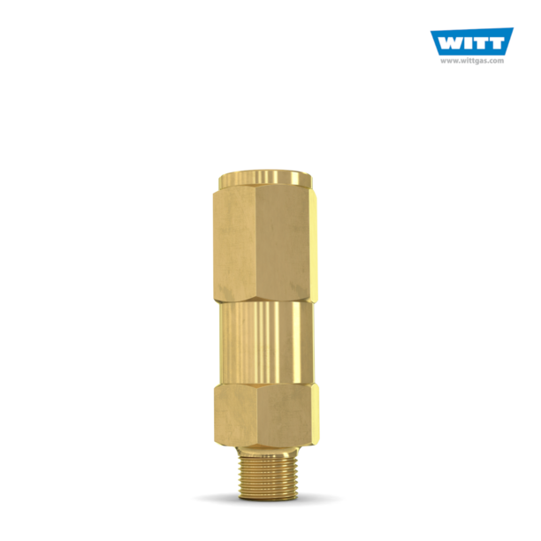
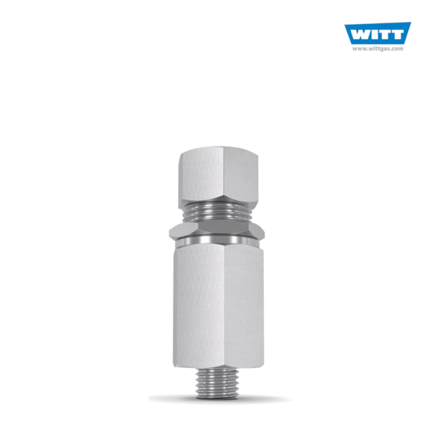
Designed especially for the protection of piping and shut-off valves where there is a possibility of trapping liquid LP-Gas or anhydrous ammonia. Available in both brass and stainless steel.

Pressure regulators reduce the high pressures of the stored gas in the cylinder to lower pressures that can be safely used in an operating system. Proper regulator selection is critical for both safety and effectiveness of operating systems. Regulators are designed to control pressure; they do not measure or control flow, unless equipped with devices such as a flow meter specifically designed for such purposes.
Regulator connections to cylinder valves must be completely free of dirt, dust, oil, and grease. "Crack" the valve slowly (by opening the valve slightly and then reclosing it) before attaching the regulator in order to blow out dust and debris from the opening. Note: Cylinders containing highly toxic gases should not be "cracked".
Regulators are attached to the cylinder, or manifold, at the inlet connection. This connection should be tested for leaks with a non-petroleum based product. Note that many soaps contain petroleum! The connection is marked with a Compressed Gas Association (CGA) number and will be left-hand or right-hand threaded to match the nut or fitting. This prevents a piece of incompatible gas equipment from being connected to the wrong gas supply.
Opening a Regulator - Stand on the valve side of the cylinder at arms length so you do not have to reach in front of the regulator face. Turn your head away from the regulator and open the valve, turning counter clockwise, to blow out dust and debris, and then reclose the valve.
Changing a Regulator - Close the valve and drain the regulator by backing out the adjusting screw. Disconnect the regulator, making sure not to touch the nut and gland areas. Connect the regulator to the new cylinder.
Closing a Regulator - Turn the valve clockwise to close the valve. Drain the regulator by turning (opening) the adjusting crew to release any gas. Reclose the adjusting screw.
Recommendation: To provide easier access and additional safety, purchase wall-mounted regulators which connect to the supply cylinder by hose. This will reduce the handling of the regulator and reduce the likelihood of damage.
Diaphragm Valve - This valve uses a two piece stem separated by non-perforated diaphragms. These diaphragms prevent leakage along the valve stem. The lower part of the stem is encased in a spring, which forces the stem away from the seat whent eh valve is opened. The upper stem is threaded into the diaphragm retainer nut. When the handwheel is rotated to the closed position, the upper stem pushes on the diaphragms, which deflect downward, forcing the lower stem against the valve seat. Advantages of this type of valve are that they provide superior leak integrity and have no threads or lubricants in the gas stream to generate particles or contaminants. This type of valve is required for mos
Compressed gas cylinders shall have a pressure relief device installed to prevent the rupture of a normally pressurized cylinder when inadvertently exposed to fire of high temperatures. There are four basic types of pressure relief devices:
Rupture Disk Devices - A flat disk typically made of metal that is designed to burst at a predetermined pressure to permit the release of gas. The pressure rating of the disk is typically stamped onto the face of the device. Examples of gases using this type of device include compressed air, argon, helium, nitrogen, and oxygen.
Fusible Plug Devices - A plug made of fusible metal designed to yield or melt at low temperatures (usually 165 or 212 degrees F). The temperature rating of the fusible metal is stamped onto the face of the device. An examples of a gas that uses this type of device is acetylene.
Combination Ruture Disks/Fusible Plug Devices - A rupture disk backed by a fusible plug. In the event of a fire, the fusible metal melts and cylinder overpressure is relieved by the bursting of the disk. The burst pressure of the disk and the melting point of the plug will be marked with the ratings. Medical grade gas cylinders typically have this type of pressure relief device.
Pressure Relief Valves - A spring-loaded valve opens when the cylinder pressure exceeds the pressure setting of the spring to discharge contents. Once the cylinder pressure decreases to the valve"s pressure setting, the valve will normally reseat without leakage.
Container assembly - An assembly consisting essentially of the container and fittings for all container openings, including shutoff valves, excess flow valves, liquid-level gaging devices, safety relief devices, and protective housing.
“Liquified petroleum gases” - “LPG” and “LP-Gas” - Any material which is composed predominantly of any of the following hydrocarbons, or mixtures of them; propane, propylene, butanes (normal butane or iso-butane), and butylenes.
Systems - an assembly of equipment consisting essentially of the container or containers, major devices such as vaporizers, safety relief valves, excess flow valves, regulators, and piping connecting such parts.
Ventilation, adequate - when specified for the prevention of fire during normal operation, ventilation shall be considered adequate when the concentration of the gas in a gas-air mixture does not exceed 25 percent of the lower flammable limit.
All liquefied petroleum gases shall be effectively odorized by an approved agent of such character as to indicate positively, by distinct odor, the presence of gas down to concentration in air of not over one-fifth the lower limit of flammability. Odorization, however, is not required if harmful in the use of further processing of the liquefied petroleum gas, or if odorization will serve no useful purpose as a warning agent in such use or further processing.
The odorization requirement of paragraph (b)(1)(i) of this section shall be considered to be met by the use of 1.0 pounds of ethyl mercaptan, 1.0 pounds of thiophane or 1.4 pounds of amyl mercaptan per 10,000 gallons of LP-Gas. However, this listing of odorants and quantities shall not exclude the use of other odorants that meet the odorization requirements of paragraph (b)(1)(i) of this section.
Each system utilizing DOT containers in accordance with 49 CFR part 178 shall have its container valves, connectors, manifold valve assemblies, and regulators approved.
In systems utilizing containers of over 2,000 gallons water capacity, each regulator, container valve, excess flow valve, gaging device, and relief valve installed on or at the container, shall have its correctness as to design, construction, and performance determined by listing by a nationally recognized testing laboratory. Refer to § 1910.7 for definition of nationally recognized testing laboratory.
Containers designed, constructed, and tested prior to July 1, 1961, according to the Code for Unfired Pressure Vessels for Petroleum Liquids and Gases, 1951 edition with 1954 Addenda, of the American Petroleum Institute and the American Society of Mechanical Engineers, which is incorporated by reference as specified in § 1910.6, shall be considered in conformance. Containers constructed according to API-ASME Code do not have to comply with section I or with appendix to section I. Paragraphs W-601 to W-606 inclusive in the 1943 and earlier editions do not apply.
The provisions of paragraph (b)(3)(i) of this section shall not be construed as prohibiting the continued use or reinstallation of containers constructed and maintained in accordance with the standard for the Storage and Handling of Liquefied Petroleum Gases NFPA No. 58 in effect at the time of fabrication.
When LP-Gas and one or more other gases are stored or used in the same area, the containers shall be marked to identify their content. Marking shall conform to the marking requirements set forth in § 1910.253(b)(1)(ii).
In the case of buildings devoted exclusively to gas manufacturing and distributing operations, the distances required by Table H-23 may be reduced provided that in no case shall containers of water capacity exceeding 500 gallons be located closer than 10 feet to such gas manufacturing and distributing buildings.
The minimum separation between liquefied petroleum gas containers and flammable liquid tanks shall be 20 feet, and the minimum separation between a container and the centerline of the dike shall be 10 feet. The foregoing provision shall not apply when LP-Gas containers of 125 gallons or less capacity are installed adjacent to Class III flammable liquid tanks of 275 gallons or less capacity.
Suitable means shall be taken to prevent the accumulation of flammable liquids under adjacent liquified petroleum gas containers, such as by diking, diversion curbs, or grading.
Valves, fittings, and accessories connected directly to the container including primary shutoff valves, shall have a rated working pressure of at least 250 p.s.i.g. and shall be of material and design suitable for LP-Gas service. Cast iron shall not be used for container valves, fittings, and accessories. This does not prohibit the use of container valves made of malleable or nodular iron.
Connections to containers, except safety relief connections, liquid level gaging devices, and plugged openings, shall have shutoff valves located as close to the container as practicable.
Excess flow valves, where required shall close automatically at the rated flows of vapor or liquid as specified by the manufacturer. The connections or line including valves, fittings, etc., being protected by an excess flow valve shall have a greater capacity than the rated flow of the excess flow valve.
Liquid level gaging devices which are so constructed that outward flow of container contents shall not exceed that passed by a No. 54 drill size opening, need not be equipped with excess flow valves.
Openings from container or through fittings attached directly on container to which pressure gage connection is made, need not be equipped with shutoff or excess flow valves if such openings are restricted to not larger than No. 54 drill size opening.
Except as provided in paragraph (c)(5)(i)(b) of this section, excess flow and back pressure check valves where required by this section shall be located inside of the container or at a point outside where the line enters the container; in the latter case, installation shall be made in such manner that any undue strain beyond the excess flow or back pressure check valve will not cause breakage between the container and such valve.
In systems where the gas in liquid form without pressure reduction enters the building, only heavy walled seamless brass or copper tubing with an internal diameter not greater than three thirty-seconds inch, and a wall thickness of not less than three sixty-fourths inch shall be used. This requirement shall not apply to research and experimental laboratories, buildings, or separate fire divisions of buildings used exclusively for housing internal combustion engines, and to commercial gas plants or bulk stations where containers are charged, nor to industrial vaporizer buildings, nor to buildings, structures, or equipment under construction or undergoing major renovation.
Pipe joints may be screwed, flanged, welded, soldered, or brazed with a material having a melting point exceeding 1,000 °F. Joints on seamless copper, brass, steel, or aluminum alloy gas tubing shall be made by means of approved gas tubing fittings, or soldered or brazed with a material having a melting point exceeding 1,000 °F.
All materials such as valve seats, packing, gaskets, diaphragms, etc., shall be of such quality as to be resistant to the action of liquefied petroleum gas under the service conditions to which they are subjected.
Hose shall be fabricated of materials that are resistant to the action of LP-Gas in the liquid and vapor phases. If wire braid is used for reinforcing the hose, it shall be of corrosion-resistant material such as stainless steel.
Hose and hose connections on the low-pressure side of the regulator or reducing valve shall be designed for a bursting pressure of not less than 125 p.s.i.g. or five times the set pressure of the relief devices protecting that portion of the system, whichever is higher.
Hose may be used on the low-pressure side of regulators to connect to other than domestic and commercial gas appliances under the following conditions:
The shutoff valve for an appliance connected by hose shall be in the metal pipe or tubing and not at the appliance end of the hose. When shutoff valves are installed close to each other, precautions shall be taken to prevent operation of the wrong valve.
Every container except those constructed in accordance with DOT specifications and every vaporizer (except motor fuel vaporizers and except vaporizers described in paragraph (b)(11)(ii)(c) of this section and paragraph (d)(4)(v)(a) of this section) whether heated by artificial means or not, shall be provided with one or more safety relief valves of spring-loaded or equivalent type. These valves shall be arranged to afford free vent to the outer air with discharge not less than 5 feet horizontally away from any opening into the building which is below such discharge. The rate of discharge shall be in accordance with the requirements of paragraph (b)(10)(ii) or (b)(10)(iii) of this section in the case of vaporizers.
Minimum required rate of discharge in cubic feet per minute of air at 120 percent of the maximum permitted start to discharge pressure for safety relief valves to be used on containers other than those constructed in accordance with DOT specification shall be as follows:
Valves not marked “Air” have flow rate marking in cubic feet per minute of liquefied petroleum gas. These can be converted to ratings in cubic feet per minute of air by multiplying the liquefied petroleum gas ratings by factors listed below. Air flow ratings can be converted to ratings in cubic feet per minute of liquefied petroleum gas by dividing the air ratings by the factors listed below.
Obtain the total surface area by adding the surface area of vaporizer shell in square feet directly in contact with LP-Gas and the heat exchanged surface area in square feet directly in contact with LP-Gas.
Container and vaporizer safety relief valves shall be set to start-to-discharge, with relation to the design pressure of the container, in accordance with Table H-26.
Safety relief devices used with systems employing containers other than those constructed according to DOT specifications shall be so constructed as to discharge at not less than the rates shown in paragraph (b)(10)(ii) of this section, before the pressure is in excess of 120 percent of the maximum (not including the 10 percent referred to in paragraph (b)(10)(iv) of this section) permitted start to discharge pressure setting of the device.
In certain locations sufficiently sustained high temperatures prevail which require the use of a lower vapor pressure product to be stored or the use of a higher designed pressure vessel in order to prevent the safety valves opening as the result of these temperatures. As an alternative the tanks may be protected by cooling devices such as by spraying, by shading, or other effective means.
Safety relief valves shall be arranged so that the possibility of tampering will be minimized. If pressure setting or adjustment is external, the relief valves shall be provided with approved means for sealing adjustment.
Shutoff valves shall not be installed between the safety relief devices and the container, or the equipment or piping to which the safety relief device is connected except that a shutoff valve may be used where the arrangement of this valve is such that full required capacity flow through the safety relief device is always afforded.
Each container safety relief valve used with systems covered by paragraphs (d), (e), (g), and (h) of this section, except as provided in paragraph (e)(3)(iii) of this section shall be plainly and permanently marked with the following: “Container Type” of the pressure vessel on which the valve is designed to be installed; the pressure in p.s.i.g. at which the valve is set to discharge; the actual rate of discharge of the valve in cubic feet per minute of air at 60 °F. and 14.7 p.s.i.a.; and the manufacturer"s name and catalog number, for example: T200-250-4050 AIR - indicating that the valve is suitable for use on a Type 200 container, that it is set to start to discharge at 250 p.s.i.g.; and that its rate of discharge is 4,050 cubic feet per minute of air as determined in subdivision (ii) of this subparagraph.
Safety relief valve assemblies, including their connections, shall be of sufficient size so as to provide the rate of flow required for the container on which they are installed.
A hydrostatic relief valve shall be installed between each pair of shut-off valves on liquefied petroleum gas liquid piping so as to relieve into a safe atmosphere. The start-to-discharge pressure setting of such relief valves shall not be in excess of 500 p.s.i.g. The minimum setting on relief valves installed in piping connected to other than DOT containers shall not be lower than 140 percent of the container relief valve setting and in piping connected to DOT containers not lower than 400 p.s.i.g. The start-to-discharge pressure setting of such a relief valve, if installed on the discharge side of a pump, shall be greater than the maximum pressure permitted by the recirculation device in the system.
The discharge from any safety relief device shall not terminate in or beneath any building, except relief devices covered by paragraphs (b)(6)(i) (a) through (e) of this section, or paragraphs (c) (4)(i) or (5) of this section.
Container safety relief devices and regulator relief vents shall be located not less than five (5) feet in any direction from air openings into sealed combustion system appliances or mechanical ventilation air intakes.
Vaporizers may be installed in buildings, rooms, sheds, or lean-tos used exclusively for gas manufacturing or distribution, or in other structures of light, noncombustible construction or equivalent, well ventilated near the floor line and roof.
When vaporizing and/or mixing equipment is located in a structure or building not used exclusively for gas manufacturing or distribution, either attached to or within such a building, such structure or room shall be separated from the remainder of the building by a wall designed to withstand a static pressure of at least 100 pounds per square foot. This wall shall have no openings or pipe or conduit passing through it. Such structure or room shall be provided with adequate ventilation and shall have a roof or at least one exterior wall of lightweight construction.
Vaporizers shall have, at or near the discharge, a safety relief valve providing an effective rate of discharge in accordance with paragraph (b)(10)(iii) of this section, except as provided in paragraph (d)(4)(v)(a), of this section.
The heating medium lines into and leaving the vaporizer shall be provided with suitable means for preventing the flow of gas into the heat systems in the event of tube rupture in the vaporizer. Vaporizers shall be provided with suitable automatic means to prevent liquid passing through the vaporizers to the gas discharge piping.
The device that supplies the necessary heat for producing steam, hot water, or other heating medium may be installed in a building, compartment, room, or lean-to which shall be ventilated near the floorline and roof to the outside. The device location shall be separated from all compartments or rooms containing liquefied petroleum gas vaporizers, pumps, and central gas mixing devices by a wall designed to withstand a static pressure of at least 100 pounds per square foot. This wall shall have no openings or pipes or conduit passing through it. This requirement does not apply to the domestic water heaters which may supply heat for a vaporizer in a domestic system.
Gas-fired heating systems supplying heat exclusively for vaporization purposes shall be equipped with automatic safety devices to shut off the flow of gas to main burners, if the pilot light should fail.
Vaporizers of less than 1 quart capacity heated by the ground or surrounding air, need not be equipped with safety relief valves provided that adequate tests demonstrate that the assembly is safe without safety relief valves.
Vaporizers may be connected to the liquid section or the gas section of the storage container, or both; but in any case there shall be at the container a manually operated valve in each connection to permit completely shutting off when desired, of all flow of gas or liquid from container to vaporizer.
Vaporizers with capacity not exceeding 35 gallons per hour shall be located at least 5 feet from container shutoff valves. Vaporizers having capacity of more than 35 gallons but not exceeding 100 gallons per hour shall be located at least 10 feet from the container shutoff valves. Vaporizers having a capacity greater than 100 gallons per hour shall be located at least 15 feet from container shutoff valves.
Vaporizers may be installed in buildings, rooms, housings, sheds, or lean-tos used exclusively for vaporizing or mixing of liquefied petroleum gas. Vaporizing housing structures shall be of noncombustible construction, well ventilated near the floorline and the highest point of the roof. When vaporizer and/or mixing equipment is located in a structure or room attached to or within a building, such structure or room shall be separated from the remainder of the building by a wall designed to withstand a static pressure of at least 100 pounds per square foot. This wall shall have no openings or pipes or conduit passing through it. Such structure or room shall be provided with adequate ventilation, and shall have a roof or at least one exterior wall of lightweight construction.
Vaporizers shall have at or near the discharge, a safety relief valve providing an effective rate of discharge in accordance with paragraph (b)(10)(iii) of this section. The relief valve shall be so located as not to be subjected to temperatures in excess of 140 °F.
Vaporizers shall be equipped with automatic safety devices to shut off the flow of gas to main burners if the pilot light should fail. When the flow through the pilot exceeds 2,000 B.t.u. per hour, the pilot also shall be equipped with an automatic safety device to shut off the flow of gas to the pilot should the pilot flame be extinguished.
Tank heaters shall be equipped with an automatic safety device to shut off the flow of gas to main burners, if the pilot light should fail. When flow through pilot exceeds 2,000 B.t.u. per hour, the pilot also shall be equipped with an automatic safety device to shut off the flow of gas to the pilot should the pilot flame be extinguished.
The vaporizer section of vaporizer-burners shall be protected by a hydrostatic relief valve. The relief valve shall be located so as not to be subjected to temperatures in excess of 140 °F. The start-to-discharge pressure setting shall be such as to protect the components involved, but not less than 250 p.s.i.g. The discharge shall be directed upward and away from component parts of the equipment and away from operating personnel.
Vaporizer-burners shall be equipped with automatic safety devices to shut off the flow of gas to the main burner and pilot in the event the pilot is extinguished.
The “filling density” is defined as the percent ratio of the weight of the gas in a container to the weight of water the container will hold at 60 °F. All containers shall be filled according to the filling densities shown in Table H-27.
are used excusively to house equipment for vaporization, pressure reduction, gas mixing, gas manufacturing, or distribution, or to house internal combustion engines, industrial processes, research and experimental laboratories, or equipment and processes using such gas and having similar hazard;
Buildings, or separate areas of buildings, used exclusively to house equipment for vaporization, pressure reduction, gas mixing, gas manufacturing, or distribution, or to house internal combustion engines, industrial processes, research and experimental laboratories, or equipment and processes using such gas and having similar hazard; and when such buildings, or separate areas thereof are constructed in accordance with this section.
A shutoff valve shall be installed in each intermediate branch line where it takes off the main line and shall be readily accessible. A shutoff valve shall also be placed at the appliance end of the intermediate branch line. Such shutoff valve shall be upstream of any flexible connector used with the appliance.
Suitable excess flow valves shall be installed in the container outlet line supplying liquid LP-Gas to the building. A suitable excess flow valve shall be installed immediately downstream of each shutoff valve. Suitable excess flow valves shall be installed where piping size is reduced and shall be sized for the reduced size piping.
Containers manufactured in accordance with specifications of 49 CFR part 178 and authorized by 49 CFR chapter 1 as a "single trip" or "nonrefillable container" shall not be refilled or reused in LP-Gas service.
Gas or liquid shall not be vented to the atmosphere to assist in transferring contents of one container to another, except as provided in paragraph (e)(5)(iv) of this section and except that this shall not preclude the use of listed pump utilizing LP-Gas in the vapor phase as a source of energy and venting such gas to the atmosphere at a rate not to exceed that from a No. 31 drill size opening and provided that such venting and liquid transfer shall be located not less than 50 feet from the nearest important building.
Marketers and users shall exercise precaution to assure that only those gases for which the system is designed, examined, and listed, are employed in its operation, particularly with regard to pressures.
Pumps or compressors shall be designed for use with LP-Gas. When compressors are used they shall normally take suction from the vapor space of the container being filled and discharge to the vapor space of the container being emptied.
Pumping systems, when equipped with a positive displacement pump, shall include a recirculating device which shall limit the differential pressure on the pump under normal operating conditions to the maximum differential pressure rating of the pump. The discharge of the pumping system shall be protected so that pressure does not exceed 350 p.s.i.g. If a recirculation system discharges into the supply tank and contains a manual shutoff valve, an adequate secondary safety recirculation system shall be incorporated which shall have no means of rendering it inoperative. Manual shutoff valves in recirculation systems shall be kept open except during an emergency or when repairs are being made to the system.
A backflow check valve, excess-flow valve, or a shutoff valve with means of remote closing, to protect against uncontrolled discharge of LP-Gas from storage tank piping shall be installed close to the point where the liquid piping and hose or swing joint pipe is connected.
Since liquefied petroleum gas is contained in a closed system of piping and equipment, the system need not be electrically conductive or electrically bonded for protection against static electricity.
Open flames (except as provided for in paragraph (b)(11) of this section), cutting or welding, portable electric tools, and extension lights capable of igniting LP-Gas, shall not be permitted within classified areas specified in Table H-28 unless the LP-Gas facilities have been freed of all liquid and vapor, or special precautions observed under carefully controlled conditions.
Fixed electrical equipment in classified areas.Fixed electrical equipment and wiring installed within classified areas specified in Table H-28 shall comply with Table H-28 and shall be installed in accordance with subpart S of this part. This provision does not apply to fixed electrical equipment at residential or commercial installations of LP-Gas systems or to systems covered by paragraph (e) or (g) of this section.
Gaging devices that require bleeding of the product to the atmosphere, such as the rotary tube, fixed tube, and slip tube, shall be designed so that the bleed valve maximum opening is not larger than a No. 54 drill size, unless provided with excess flow valve.
The maximum volume of LP-Gas which can be placed in a container when determining the length of the dip tube expressed as a percentage of total water content of the container is calculated by the following formula.
The maximum weight of LP-Gas which may be placed in a container for determining the length of a fixed dip tube is determined by multiplying the maximum volume of liquefied petroleum gas obtained by the formula in paragraph (b)(19)(b) of this section by the pounds of liquefied petroleum gas in a gallon at 40 °F. for abovegound and at 50 °F. for underground containers. For example, typical pounds per gallon are specified below:
[(Maximum volume of LP-Gas (from formula in subdivision (b) of this subdivision) × 100) ÷ Total water content of container in gallons] = Maximum percent of LP-Gas
Gage glasses of the columnar type shall be restricted to charging plants where the fuel is withdrawn in the liquid phase only. They shall be equipped with valves having metallic handwheels, with excess flow valves, and with extra-heavy glass adequately protected with a metal housing applied by the gage manufacturer. They shall be shielded against the direct rays of the sun. Gage glasses of the columnar type are prohibited on tank trucks, and on motor fuel tanks, and on containers used in domestic, commercial, and industrial installations.
Gaging devices of the float, or equivalent type which do not require flow for their operation and having connections extending to a point outside the container do not have to be equipped with excess flow valves provided the piping and fittings are adequately designed to withstand the container pressure and are properly protected against physical damage and breakage.
Any appliance that was originally manufactured for operation with a gaseous fuel other than LP-Gas and is in good condition may be used with LP-Gas only after it is properly converted, adapted, and tested for performance with LP-Gas before the appliance is placed in use.
Unattended heaters used inside buildings for the purpose of animal or poultry production or care shall be equipped with an approved automatic device designed to shut off the flow of gas to the main burners, and pilot if used, in the event of flame extinguishment.
Industrial appliances - NFPA 54A-1969, Standard for the Installation of Gas Piping and Gas Equipment on Industrial Premises and Certain Other Premises.
Description of a system. A system shall include the container base or bracket, containers, container valves, connectors, manifold valve assembly, regulators, and relief valves.
Except as provided in paragraph (b)(10)(xiii) of this section, the discharge from safety relief devices shall be located not less than 3 feet horizontally away from any building opening which is below the level of such discharge and shall not terminate beneath any building unless such space is well ventilated to the outside and is not enclosed on more than two sides.
Systems utilizing containers having a water capacity greater than 2½ pounds (nominal 1 pound LP-Gas capacity) shall be equipped with excess flow valves. Such excess flow valves shall be either integral with the container valves or in the connections to the container valve outlets. In either case, an excess flow valve shall be installed in such a manner that any undue strain beyond the excess flow valve will not cause breakage between the container and the excess flow valve. The installation of excess flow valves shall take into account the type of valve protection provided.
Regulators, if used, shall be either directly connected to the container valves or to manifolds connected to the container values. The regulator shall be suitable for use with LP-Gas. Manifolds and fittings connecting containers to pressure regulator inlets shall be designed for at least 250 p.s.i.g. service pressure.
Portable heaters, including salamanders, shall be equipped with an approved automatic device to shut off the flow of gas to the main burner, and pilot if used, in the event of flame extinguishment. Such heaters having inputs above 50,000 B.t.u. manufactured on or after May 17, 1967, and such heaters having inputs above 100,000 B.t.u. manufactured before May 17, 1967, shall be equipped with either.
The provisions of this paragraph (h) do not apply to tar kettle burners, torches, melting pots, nor do they apply to portable heaters under 7,500 B.t.u.h. input when used with containers having a maximum water capacity of 2½ pounds. Container valves, connectors, regulators, manifolds, piping, and tubing shall not be used as structural supports for heaters.
Containers having a water capacity greater than 2½ pounds (nominal 1 pound LP-Gas capacity) connected for use, shall stand on a firm and substantially level surface and, when necessary, shall be secured in an upright position.
Containers, including the valve protective devices, shall be installed so as to minimize the probability of impingement of discharge of safety relief devices upon containers.
Containers having a maximum water capacity of 2½ pounds (nominal 1 pound LP-Gas capacity) are permitted to be used inside of buildings as part of approved self-contained hand torch assemblies or similar appliances.
Containers having a maximum water capacity of 12 pounds (nominal 5 pounds LP-Gas capacity) are permitted to be used temporarily inside of buildings for public exhibition or demonstration purposes, including use for classroom demonstrations.
For temporary heating such as curing concrete, drying plaster and similar applications, heaters (other than integral heater-container units) shall be located at least 6 feet from any LP-Gas container. This shall not prohibit the use of heaters specifically designed for attachment to the container or to a supporting standard, provided they are designed and installed so as to prevent direct or radiant heat application from the heater onto the container. Blower and radiant type heaters shall not be directed toward any LP-Gas container within 20 feet.
When heaters are connected to containers for use in an unpartitioned area on the same floor, the total water capacity of containers manifolded together for connection to a heater or heaters shall not be greater than 735 pounds (nominal 300 pounds LP-Gas capacity). Such manifolds shall be separated by at least 20 feet.
Where more than one manifold having a total water capacity greater than 735 pounds (nominal 300 pounds LP-Gas capacity) are located in the same unpartitioned area, they shall be separated by at least 50 feet.
Containers connected to a manifold shall have a total water capacity not greater than 735 pounds (nominal 300 pounds LP-Gas capacity) and not more than one such manifold may be located in the same room unless separated at least 20 feet from a similar unit.
The maximum water capacity of individual containers shall be 245 pounds (nominal 100 pounds LP-Gas capacity), but the maximum quantity of LP-Gas that may be placed in each container shall be 20 pounds.
Valves in the assembly of multiple container systems shall be arranged so that replacement of containers can be made without shutting off the flow of gas in the system.
Regulators and low-pressure relief devices shall be rigidly attached to the cylinder valves, cylinders, supporting standards, the building walls or otherwise rigidly secured and shall be so installed or protected that the elements (sleet, snow, or ice) will not affect their operation.
By ventilated cap or collar, fastened to the container capable of withstanding a blow from any direction equivalent to that of a 30-pound weight dropped 4 feet. Construction must be such that a blow will not be transmitted to the valve or other connection.
When containers are not connected to the system, the outlet valves shall be kept tightly closed or plugged, even though containers are considered empty.
Containers having a water capacity in excess of 50 pounds (approximately 21 pounds LP-Gas capacity), recharged at the installation, shall be provided with excess flow or backflow check valves to prevent the discharge of container contents in case of failure of the filling or equalizing connection.
A final stage regulator of an LP-Gas system (excluding any appliance regulator) shall be equipped on the low-pressure side with a relief valve which is set to start to discharge within the limits specified in Table H-30.
When a regulator or pressure relief valve is used inside a building for other than purposes specified in paragraphs (b)(6)(i) (a)-(g) of this section, the relief valve and the space above the regulator and relief valve diaphragms shall be vented to the outside air with the discharge outlet located not less than 3 feet horizontally away from any building opening which is below such discharge. These provisions do not apply to individual appliance regulators when protection is otherwise provided nor to paragraph (c)(5) of this section and paragraph (b)(10)(xiii) of this section. In buildings devoted exclusively to gas distribution purposes, the space above the diaphragm need not be vented to the outside.
All openings in a container shall be equipped with approved automatic excess flow valves except in the following: Filling connections as provided in paragraph (d)(3)(ii) of this section; safety relief connections, liquid-level gaging devices as provided in paragraphs (b)(7)(iv), (19)(iii), and (19)(viii) of this section; pressure gage connections as provided in paragraph (b)(7)(v) of this section, as provided in paragraphs (d) (iv), (vi), and (vii) of this section.
The controlling orifice between the contents of the container and the outlet of the shutoff valve does not exceed five-sixteenths inch in diameter for vapor withdrawal systems and one-eighth inch in diameter for liquid withdrawal systems.
An approved pressure-reducing regulator is directly attached to the outlet of the shutoff valve and is rigidly supported, or that an approved pressure-reducing regulator is attached to the outlet of the shutoff valve by means of a suitable flexible connection, provided the regulator is adequately supported and properly protected on or at the tank.
All inlet and outlet connections except safety relief valves, liquid level gaging devices and pressure gages on containers of 2,000 gallons water capacity, or more, and on any container used to supply fuel directly to an internal combustion engine, shall be labeled to designate whether they communicate with vapor or liquid space. Labels may be on valves.
In lieu of an excess flow valve openings may be fitted with a quick-closing internal valve which, except during operating periods shall remain closed. The internal mechanism for such valves may be provided with a secondary control which shall be equipped with a fusible plug (not over 220 °F. melting point) which will cause the internal valve to close automatically in case of fire.
In industrial and gas manufacturing plants, discharge pipe from safety relief valves on pipe lines within a building shall discharge vertically upward and shall be piped to a point outside a building.
Safety relief device discharge terminals shall be so located as to provide protection against physical damage and such discharge pipes shall be fitted with loose raincaps. Return bends and restrictive pipefittings shall not be permitted.
If desired, discharge lines from two or more safety relief devices located on the same unit, or similar lines from two or more different units, may be run into a common discharge header, provided that the cross-sectional area of such header be at least equal to the sum of the cross-sectional area of the individual discharge lines, and that the setting of safety relief valves are the same.
A final stage regulator of an LP-Gas system (excluding any appliance regulator) shall be equipped on the low-pressure side with a relief valve which is set to start to discharge within the limits specified in Table H-30.
When a regulator or pressure relief valve is installed inside a building, the relief valve and the space above the regulator and relief valve diaphragms shall be vented to the outside air with the discharge outlet located not less than 3 feet horizontally away from any opening into the building which is below such discharge. (These provisions do not apply to individual appliance regulators when protection is otherwise provided. In buildings devoted exclusively to gas distribution purposes, the space above the diaphragm need not be vented to the outside.)
Containers of 1,200 gallons water capacity or less which may contain liquid fuel when installed above ground shall have the rate of discharge required by paragraph (b)(10)(ii) of this section provided by a spring-loaded relief valve or valves. In addition to the required spring-loaded relief valve(s), suitable fuse plug(s) may be used provided the total discharge area of the fuse plug(s) for each container does not exceed 0.25 square inch.
The fusible metal of the fuse plugs shall have a yield temperature of 208 °F. minimum and 220 °F. maximum. Relief valves and fuse plugs shall have direct communication with the vapor space of the container.
On a container having a water capacity greater than 125 gallons, but not over 2,000 gallons, the discharge from the safety relief valves shall be vented away from the container vertically upwards and unobstructed to the open air in such a manner as to prevent any impingement of escaping gas upon the container; loose-fitting rain caps shall be used. Suitable provision shall be made for draining condensate which may accumulate in the relief valve or its discharge pipe.
On containers of 125 gallons water capacity or less, the discharge from safety relief devices shall be located not less than 5 feet horizontally away from any opening into the building below the level of such discharge.
On a container having a water capacity greater than 2,000 gallons, the discharge from the safety relief valves shall be vented away from the container vertically upwards to a point at least 7 feet above the container, and unobstructed to the open air in such a manner as to prevent any impingement of escaping gas upon the container; loose-fitting rain caps shall be used. Suitable provision shall be made so that any liquid or condensate that may accumulate inside of the safety relief valve or its discharge pipe will not render the valve inoperative. If a drain is used, a means shall be provided to protect the container, adjacent containers, piping, or equipment against impingement of flame resulting from ignition of product escaping from the drain.
On all containers which are installed underground and which contain no liquid fuel until buried and covered, the rate of discharge of the spring-loaded relief valve installed thereon may be reduced to a minimum of 30 percent of the rate of discharge specified in paragraph (b)(10)(ii) of this section. Containers so protected shall not be uncovered after installation until the liquid fuel has been removed therefrom. Containers which may contain liquid fuel before being installed under ground and before being completely covered with earth are to be considered aboveground containers when determining the rate of discharge requirement of the relief valves.
On underground containers of more than 2,000 gallons water capacity, the discharge from safety relief devices shall be piped vertically and directly upward to a point at least 7 feet above the ground.
Where there is a probability of the manhole or housing becoming flooded, the discharge from regulator vent lines shall be above the highest probable water level. All manholes or housings shall be provided with ventilated louvers or their equivalent, the area of such openings equaling or exceeding the combined discharge areas of the safety relief valves and other vent lines which discharge their content into the manhole housing.
Vaporizers of less than 1 quart total capacity, heated by the ground or the surrounding air, need not be equipped with safety relief valves provided that adequate tests certified by any of the authorities referred to in paragraph (b)(2) of this section, demonstrate that the assembly is safe without safety relief valves.
In industrial and gas manufacturing plants, safety relief valves on vaporizers within a building shall be piped to a point outside the building and be discharged upward.
Reinstallation of containers. Containers may be reinstalled if they do not show any evidence of harmful external corrosion or other damage. Where containers are reinstalled underground, the corrosion resistant coating shall be put in good condition (see paragraph (c)(7)(vi) of this section). Where containers are reinstalled above ground, the safety devices and gaging devices shall comply with paragraph (c)(4) of this section and paragraph (b)(19) of this section respectively for aboveground containers.
Flanges, nozzles, valves, fittings, and the like, having communication with the interior of the container, shall be protected against physical damage.
Skids, or lugs for attachment of skids, shall be secured to the container in accordance with the code or rules under which the container is designed and built (with a minimum factor of safety of four) to withstand loading in any direction equal to four times the weight of the container and attachments when filled to the maximum permissible loaded weight.
Container assemblies listed for interchangeable installation above ground or under ground shall conform to the requirements for aboveground installations with respect to safety relief capacity and filling density. For installation above ground all other requirements for aboveground installations shall apply. For installation under ground all other requirements for underground installations shall apply.
Valves, regulating, gaging, and other container accessory equipment shall be protected against tampering and physical damage. Such accessories shall also be so protected during the transit of containers intended for installation underground.
On underground or combination aboveground-underground containers, the service valve handwheel, the terminal for connecting the hose, and the opening through which there can be a flow from safety relief valves shall be at least 4 inches above the container and this opening shall be located in the dome or housing. Underground systems shall be so installed that all the above openings, including the regulator vent, are located above the normal maximum water table.
Drips for condensed gas. Where vaporized gas on the low-pressure side of the system may condense to a liquid at normal operating temperatures and pressures, suitable means shall be provided for revaporization of the condensate.
If loading and unloading are normally done during other than daylight hours, adequate lights shall be provided to illuminate storage containers, control valves, and other equipment.


 8613371530291