
marine boiler safety valve free sample
Boiler explosions have been responsible for widespread damage to companies throughout the years, and that’s why today’s boilers are equipped with safety valves and/or relief valves. Boiler safety valves are designed to prevent excess pressure, which is usually responsible for those devastating explosions. That said, to ensure that boiler safety valves are working properly and providing adequate protection, they must meet regulatory specifications and require ongoing maintenance and periodic testing. Without these precautions, malfunctioning safety valves may fail, resulting in potentially disastrous consequences.
Boiler safety valves are activated by upstream pressure. If the pressure exceeds a defined threshold, the valve activates and automatically releases pressure. Typically used for gas or vapor service, boiler safety valves pop fully open once a pressure threshold is reached and remain open until the boiler pressure reaches a pre-defined, safe lower pressure.
Boiler relief valves serve the same purpose – automatically lowering boiler pressure – but they function a bit differently than safety valves. A relief valve doesn’t open fully when pressure exceeds a defined threshold; instead, it opens gradually when the pressure threshold is exceeded and closes gradually until the lower, safe threshold is reached. Boiler relief valves are typically used for liquid service.
There are also devices known as “safety relief valves” which have the characteristics of both types discussed above. Safety relief valves can be used for either liquid or gas or vapor service.
Nameplates must be fastened securely and permanently to the safety valve and remain readable throughout the lifespan of the valve, so durability is key.
The National Board of Boiler and Pressure Vessel Inspectors offers guidance and recommendations on boiler and pressure vessel safety rules and regulations. However, most individual states set forth their own rules and regulations, and while they may be similar across states, it’s important to ensure that your boiler safety valves meet all state and local regulatory requirements.
The National Board published NB-131, Recommended Boiler and Pressure Vessel Safety Legislation, and NB-132, Recommended Administrative Boiler and Pressure Vessel Safety Rules and Regulationsin order to provide guidance and encourage the development of crucial safety laws in jurisdictions that currently have no laws in place for the “proper construction, installation, inspection, operation, maintenance, alterations, and repairs” necessary to protect workers and the public from dangerous boiler and pressure vessel explosions that may occur without these safeguards in place.
The American Society of Mechanical Engineers (ASME) governs the code that establishes guidelines and requirements for safety valves. Note that it’s up to plant personnel to familiarize themselves with the requirements and understand which parts of the code apply to specific parts of the plant’s steam systems.
High steam capacity requirements, physical or economic constraints may make the use of a single safety valve impossible. In these cases, using multiple safety valves on the same system is considered an acceptable practice, provided that proper sizing and installation requirements are met – including an appropriately sized vent pipe that accounts for the total steam venting capacity of all valves when open at the same time.
The lowest rating (MAWP or maximum allowable working pressure) should always be used among all safety devices within a system, including boilers, pressure vessels, and equipment piping systems, to determine the safety valve set pressure.
Avoid isolating safety valves from the system, such as by installing intervening shut-off valves located between the steam component or system and the inlet.
Contact the valve supplier immediately for any safety valve with a broken wire seal, as this indicates that the valve is unsafe for use. Safety valves are sealed and certified in order to prevent tampering that can prevent proper function.
Avoid attaching vent discharge piping directly to a safety valve, which may place unnecessary weight and additional stress on the valve, altering the set pressure.

The steam will condenses and partial vacuum occurred and move back the water thealong the pipe with very high velocity, and the water will strike at the vent or valves.
Once being dose into the boiler water floating solid particles and suspended solid are settled tothe bottom of the boiler and easily remove by blowing down.
All safety valves are to be set to operate under steam a little above working pressure not greaterthan 3% above the approve working pressure of the boiler.
A ship’s engine room is a complex arrangement of machinery and systems, which is used in carrying out various operations on board. One such important machinery, which has been assisting ships since the start of shipping, is the marine boiler.
Earlier, marine boilers were primarily installed on a ship for the propulsion plant, which used to run on steam (steam engine). Today, the steam generated by the boiler is utilized in various systems in the engine room, including heating of fuel for the main engine. Considering the importance of marine boilers and the risks involved with its operation on ships, there has been constant development in the industry to enhance boiler safety on board. Some even consider it one of the “deadliest” machinery systems on board.
Boiler Explosion: Many cases of boiler explosion in the past have shown how dangerous marine boiler can be if not operated professionally. Accidents happen when the fuel system within the boiler is mishandled, or when the steam pressure inside the boiler drum is not regulated.
Boiler Fire/ Meltdown: The boiler fire is another type of accident which can destroy all the tubes inside the boiler and lead to an explosion or spreading of fire within the ship.
Hot Surface: The boiler and the associated pipes, valves, and auxiliaries have a very hot surface as they carry steam to different parts of the ship. A direct skin contact with any of the exposed surface will lead to severe burn.
Other Risks: Other risks such as high pressurized parts, handling harmful chemicals, moving machinery etc. are also associated with operating marine boilers.
Needless to say, safety is a critical aspect when operating a high or even a low-pressure boiler on a ship and therefore different marine boiler devices are provided.
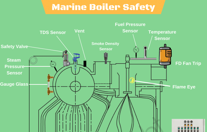
Boiler Safety System and Instruments: A modern marine boiler is fitted with several safety devices for the protection of the operator. For easy understanding, let us divide these instruments/devices as per the system they are fitted in –
Steam Safety System: The steam system in the boiler is a high pressure, high-temperature area. To safeguard the operator and the boiler itself, it is fitted with the following safety features:
Pressure gauge: Multiple pressure gauges are fitted to ensure the operator has an idea of the current value of pressure inside the boiler. Usually, two pressure gauges are fitted on the boiler and one line is taken from the steam drum to the engine control room, to display the steam pressure remotely.
The pressure gauges are also incorporated with cut-in and cut-out automation systems, i.e. the input from the pressure gauges are used to operate the boiler burner. When the pressure reaches the set value, the boiler burner will stop firing and when the pressure drops to a lower set value, the burner will be switched ON to raise the boiler pressure.
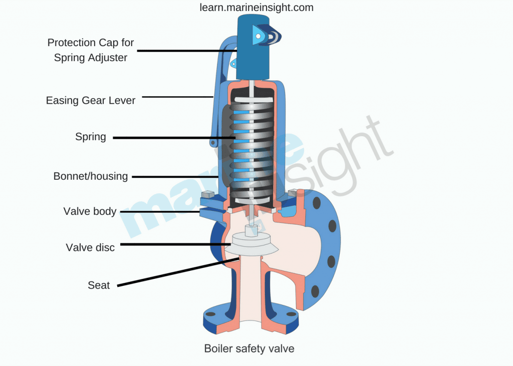
Safety Valve: Boiler safety valve is an extremely important safety equipment fitted on the steam drum of the boiler. As per SOLAS chapter II-1, every steam boiler and every un-fired steam generator shall be provided with not less than 2 safety valves of adequate capacity. However, with regards to the output or any other feature of a boiler or un-fired steam generator, the administration may permit only one safety valve to be fitted if adequate protection against overpressure is thereby satisfactorily provided.
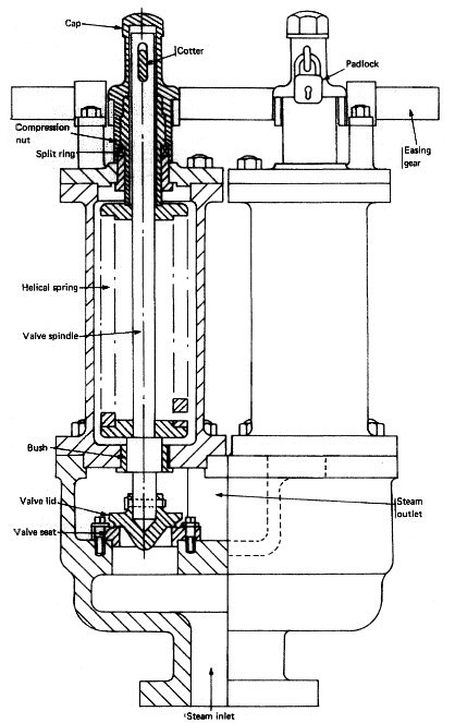
Usually, an improved high lift is one of the most popular types of safety valves used on a ship. They are set to lift at the blow-off pressure and shut when the pressure reduces to the safe limit. They are set to open at 3 % above working pressure. The lift of valve is one-twelfth of the valve diameter.
Easing Gear: The easing gear is attached to the boiler safety valve. Every individual safety valve is provided with its own easing gear, which is a pulley and wire arrangement (connected to the lever of the safety valve) with an accessible handle at the lower operating boiler platform. It is used to lift the boiler safety valve in case of an emergency (without getting near to the safety valve) and to regularly test the operation of the safety valves.
Boiler Vent: Vent on the boiler drum is required to ensure boiler does not implode once it is shut down. It is normally opened when the pressure gauge shows the reading below 0.5 bars.
Water Safety System: The water system is a high-temperature system and the level and quality of the water inside the water drum plays a crucial role in the safe operation of the boiler. Following are the equipment/system fitted on the water side of the marine boiler:
Low / high water level alarm and cutout: The boiler water drum is fitted with a level sensor, which will continuously monitor the level of water inside the drum. A full drum will carry over the water or will have no space to generate steam, thus reducing the efficiency of the boiler; whereas low or no water level in the drum will lead to over-heating of tubes and can lead to fire or meltdown of the complete boiler.
The low/ high water level provides an early warning to the operator for taking appropriate action to manage the water level inside the boiler water drum.
Too low water level alarm and shut down: The initial warning provided by the above arrangement (low/high water level alarm), may not be sufficient for the operator as there can be a major leak in the tubes, leading to a reduction in the water level. A secondary safety is therefore provided i.e. Too low water level alarm and shut down, which will stop the burner firing to control the overheating of the boiler internal parts.
Water level indicators: The boiler is fitted with multiple water level indicators to make it easy for the operator to see the water drum level and ensure operational safety of the boiler.
Local gauge glasses are provided in a duplex on the boiler drum to ensure at least one gauge glass is operational in case one stops showing the level. Remote water level indicators such as a differential pressure water level sensor, probe level sensor etc. are also provided to indicate the current level in the drum at a remote position such as the engine control room.
Salinity Sensor: The boiler drum is fitted with a salinity sensor, which continuously monitors the dissolved solids content in the water. If the solid (e.g. salt) content exceeds the set value, it trips the boiler to ensure the tubes and boiler internals does not get affected due to the contamination. The operator should either blow down the boiler and feed fresh water to the drum to eliminate the cause which is resulting in high salinity (for e.g. leakage in the condenser)
Fuel Safety System: The boiler is provided with heavy or marine gas fuel oil for generating the heat in the furnace. To ensure the fuel system is operating efficiently, it is fitted with the following boiler safety features:
Low / high fuel oil temperature alarm: Modern marine boilers are meant to operate in different grades of fuel due to the port / ECA regulations for minimizing the air pollution from the ship. The oil temperature is an important factor as it controls the viscosity of the fuel which is directly related to atomization and efficient combustion inside the furnace. If the fuel temperature is not at its set value (which will vary for different grades), the alarm will sound. The operator must stop the alarm and the oil temperature should be brought to normal before restarting the boiler.
Smoke Density alarm: With more stringent rules coming up for environmental protection, the boiler exhaust is fitted with a smoke density sensor which detects the post-combustion product, especially during starting of a boiler and at low loads. If the smoke density is higher than the required value, it will sound an alarm to which the operator needs to check the combustion of the boiler
Operational Safety: Automation, alarms, and warnings have made the life of seafarers on ships a lot easier than what it used to be in terms of boiler safety. However, professional engineers rarely depend on them and always rely on the best practice for efficiently running the machinery.
Efficient hot well/ cascade tank function: Maintaining the correct hot-well temperature will decrease the steam production time of the boiler compared to a low-temperature water supply by the cascade tank
Routine furnace inspection: Boiler furnace is responsible to contain the heat within the boiler and to reduce the surface heat loss. Maintaining the furnace refractory will lead to efficient boiler steam production
Lagging: Once the steam comes out of the boiler via main steam stop valve, it is supplied to several systems via pipes and distribution valves. A proper lagging on the pipes and valves will ensure the boiler need not run extra as the steam loss will be contained. Also, it ensures the safety of ship staff from surface burns.
Maintenance: On-time maintenance such as testing of safety valve, cleaning of boiler tubes etc. will result in safe and efficient working of the marine boiler.
Disclaimer:The authors’ views expressed in this article do not necessarily reflect the views of Marine Insight. Data and charts, if used, in the article have been sourced from available information and have not been authenticated by any statutory authority. The author and Marine Insight do not claim it to be accurate nor accept any responsibility for the same. The views constitute only the opinions and do not constitute any guidelines or recommendation on any course of action to be followed by the reader.
An ardent sailor and a techie, Anish Wankhede has voyaged on a number of ships as a marine engineer officer. He loves multitasking, networking, and troubleshooting. He is the one behind the unique creativity and aesthetics at Marine Insight.
Operating controls for boilers could be broadly defined to include burner management controls; however, this inspector guide will be limited to the pressure and temperature operating controls required by the ASME BPV Code for steam and hot water boilers.
Steam boilers require a device which senses steam pressure and cycles the burner or other source of heat in order to maintain a consistent, predetermined operating pressure. A second device is used to prevent the boiler from exceeding the maximum allowable working pressure (MAWP) indicated on the boiler nameplate.
Hot-water boilers require a device which senses water temperature and cycles the burner or other source of heat in order to maintain a consistent, predetermined operating temperature. A second device is used to prevent the boiler from exceeding the design temperature of an ASME BPV Code Section I boiler or the maximum water temperature indicated on an ASME BPV Code Section IV boiler nameplate.
The secondary device referenced above for both steam and hot-water boilers is referred to as a high-limit control and under normal conditions, would never be called upon to operate. However, if the primary, or operating, control should fail, the high-limit control must operate, stopping the burner or other source of heat. Some high-limit controls incorporate a manual reset. The purpose of this is to alert the operator that the high-limit control has been activated. The operator should then look for the problem which caused the high-limit control to activate before resetting the device and restarting the boiler.
ASME BPV Code Section I does not specifically mandate pressure or temperature controls but they will be found, in one form or another, on almost all ASME BPV Code Section I boilers. In addition, ASME Standard CSD-1 (if applicable) requires the controls on boilers with input ratings up to 12,500,000 Btu/hr. Jurisdictional regulations will specify the use of ASME Standard CSD-1 if it is mandated.
A pressure control must be installed so as to always sense pressure from the steam space of the boiler. The ASME BPV Code requirements and device manufacturer"s instructions should be followed for any installation details. When a siphon or pigtail is used to prevent live steam from entering and damaging the device, the orientation of the siphon loop is critical to the proper operation of a device containing a mercury switch. If the siphon loop is installed in the incorrect orientation shown in Figure 1, movement of the loop caused by heat and/or pressure can cause the mercury switch in the device to activate or deactivate at other than the set pressure.
Either type of operating control can be bypassed electrically with jumper wires. Jumper wires can be used legitimately by qualified service personnel during maintenance and testing, but must be removed before returning the boiler to normal operation. Jumper wires could be used inappropriately in an attempt to permanently bypass a control which has malfunctioned and will not allow the boiler to operate.
While inspecting low-pressure or high-pressure boilers, the inspector will be observing operating controls. The inspector must take the time necessary to completely evaluate the condition and operational effectiveness of these controls. The inspector should:
Compare the pressure gage reading on a steam boiler with the set pressure of the primary operating control. If the pressure gage reading is higher than the set pressure of the control, request the installation of a second, reliable pressure gage in order to determine the accuracy of the first pressure gage. If the second pressure gage reading agrees with the operating control set pressure, the first pressure gage must be recalibrated or replaced. If, however, the second pressure gage reading agrees with the first pressure gage, the boiler should be removed from service until the primary operating control can be repaired or replaced.
Compare the thermometer reading on a hot-water boiler with the set temperature of the primary operating control. If the thermometer reading is higher than the set temperature of the control, request the installation of a second, reliable thermometer in order to determine the accuracy of the first thermometer. If the second thermometer reading agrees with the operating control set temperature, the first thermometer must be recalibrated or replaced. If, however, the second thermometer reading agrees with the first thermometer, the boiler should be removed from service until the primary operating control can be repaired or replaced
Request the owner or owner"s representative test the high-limit control in accordance with the control manufacturer"s instructions. This test may involve disabling the primary operating control or setting the primary control"s pressure or temperature, as applicable, higher than the setting of the high-limit control. Since each installation can be unique, the inspector should rely on the control manufacturer"s instructions for guidance. Before returning the boiler to its normal operating condition, ensure all operating controls are enabled and set to the proper pressure or temperature.

The primary purpose of a safety valve is to protect life, property and the environment. Safety valves are designed to open and release excess pressure from vessels or equipment and then close again.
The function of safety valves differs depending on the load or main type of the valve. The main types of safety valves are spring-loaded, weight-loaded and controlled safety valves.
Regardless of the type or load, safety valves are set to a specific set pressure at which the medium is discharged in a controlled manner, thus preventing overpressure of the equipment. In dependence of several parameters such as the contained medium, the set pressure is individual for each safety application.


 8613371530291