
midland safety valve factory

A chemical leak in a railcar"s valve or fitting connection can be hazardous, not only to rail personnel, but to the environment and local populations. Midland"s Emergency Response Kit (ERK) has been designed to allow for the quick and safe capping of leaking fittings on the top of pressurized railcars.
Midland Pressure Relief Valves offer performance, reliability and flexibility of use in one easy to maintain, reliable product design. Interior and exterior valve body designs are available in every DOT pressure rating, from 225 psig to 495 psig, and flow rates up to 49,912 scfm. Midland provides the appropriate valve to meet your application needs.
Plus, Midland experience delivers technically superior products that perform over the long haul. Seals are easily replaced for use with diverse commodities to maximize the in-service time of every tank car. Sealed spring chambers and bubble-tight seal testing of every valve assure long-life and safe operation, even when used in harsh chemical environments.

Midland Pressure Relief Valves offer performance, reliability and flexibility of use in one easy to maintain, reliable product design. Exterior valve body designs are available in every DOT pressure rating, from 75 psig to 165 psig, and flow rates up to 30,000 SCFM. Midland provides the appropriate valve to meet your application needs.
Plus, Midland"s experience delivers technically superior products that perform over the long haul. Seals are easily replaced for use with diverse commodities to maximize the in-service time of every tank car. Sealed spring chambers and bubble-tight seal testing of every valve assure long-life and safe operation, even when used in harsh chemical environments.

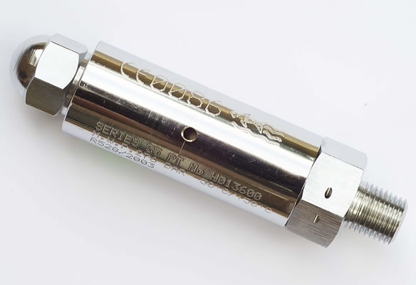
All models feature a manually adjustable safety relief vent pressure, and can be optionally factory set, wire-locked and tagged for a small £3.40 charge (please quote code ZWL and your requested setting when ordering).

Midland Pressure Relief Valves offer performance, reliability and flexibility of use in one easy to maintain, reliable product design. Interior and exterior valve body designs are available in every DOT pressure rating, from 75 psig to 165 psig, and flow rates up to 35,608 scfm. Midland provides the appropriate valve to meet your application needs.

Sierra Valve & Equipment has been one of Midland, TX"s top stainless steel & valve actuators specialists since 2003! With the largest selection ofvalves & fittingsin the West Texas area, we are confident that we can fulfill your needs. With a fully stocked warehouse, our team is able to complete orders quickly, and can ship anywhere in the Permian Basin, including Odessa, Midland, Pecos, TX as well as Carlsbad and Hobbs, NM. Plus, same day service is also available to most customers.

ADVERTISEMENTCanadian-based Kelso Technologies Inc., a railcar equipment developer, received approval of its external, stem-free JS75H pressure relief valve from the Association of American Railroads in mid-October. The new model doesn"t have O-rings and doesn"t require pneumatic tools�features that offer maximum operator safety and performance, according to Kelso Technologies President John Carswell.
In Skokie, Ill., Midland Manufacturing, a railroad tank car safety valve producer, introduced its new A-2165 pressure relief valve. According to Kevin Cook, Midland vice president of sales and marketing, the valve has a start-to-discharge weight of 165 pounds, as opposed to the traditional 75 pounds. Its O-ring seal also prevents leakage and optimizes flow rates for increased operator safety.
A safety valve is a valve that acts as a fail-safe. An example of safety valve is a pressure relief valve (PRV), which automatically releases a substance from a boiler, pressure vessel, or other system, when the pressure or temperature exceeds preset limits. Pilot-operated relief valves are a specialized type of pressure safety valve. A leak tight, lower cost, single emergency use option would be a rupture disk.
Safety valves were first developed for use on steam boilers during the Industrial Revolution. Early boilers operating without them were prone to explosion unless carefully operated.
Vacuum safety valves (or combined pressure/vacuum safety valves) are used to prevent a tank from collapsing while it is being emptied, or when cold rinse water is used after hot CIP (clean-in-place) or SIP (sterilization-in-place) procedures. When sizing a vacuum safety valve, the calculation method is not defined in any norm, particularly in the hot CIP / cold water scenario, but some manufacturers
The earliest and simplest safety valve was used on a 1679 steam digester and utilized a weight to retain the steam pressure (this design is still commonly used on pressure cookers); however, these were easily tampered with or accidentally released. On the Stockton and Darlington Railway, the safety valve tended to go off when the engine hit a bump in the track. A valve less sensitive to sudden accelerations used a spring to contain the steam pressure, but these (based on a Salter spring balance) could still be screwed down to increase the pressure beyond design limits. This dangerous practice was sometimes used to marginally increase the performance of a steam engine. In 1856, John Ramsbottom invented a tamper-proof spring safety valve that became universal on railways. The Ramsbottom valve consisted of two plug-type valves connected to each other by a spring-laden pivoting arm, with one valve element on either side of the pivot. Any adjustment made to one of valves in an attempt to increase its operating pressure would cause the other valve to be lifted off its seat, regardless of how the adjustment was attempted. The pivot point on the arm was not symmetrically between the valves, so any tightening of the spring would cause one of the valves to lift. Only by removing and disassembling the entire valve assembly could its operating pressure be adjusted, making impromptu "tying down" of the valve by locomotive crews in search of more power impossible. The pivoting arm was commonly extended into a handle shape and fed back into the locomotive cab, allowing crews to "rock" both valves off their seats to confirm they were set and operating correctly.
Safety valves also evolved to protect equipment such as pressure vessels (fired or not) and heat exchangers. The term safety valve should be limited to compressible fluid applications (gas, vapour, or steam).
For liquid-packed vessels, thermal relief valves are generally characterized by the relatively small size of the valve necessary to provide protection from excess pressure caused by thermal expansion. In this case a small valve is adequate because most liquids are nearly incompressible, and so a relatively small amount of fluid discharged through the relief valve will produce a substantial reduction in pressure.
Flow protection is characterized by safety valves that are considerably larger than those mounted for thermal protection. They are generally sized for use in situations where significant quantities of gas or high volumes of liquid must be quickly discharged in order to protect the integrity of the vessel or pipeline. This protection can alternatively be achieved by installing a high integrity pressure protection system (HIPPS).
In the petroleum refining, petrochemical, chemical manufacturing, natural gas processing, power generation, food, drinks, cosmetics and pharmaceuticals industries, the term safety valve is associated with the terms pressure relief valve (PRV), pressure safety valve (PSV) and relief valve.
The generic term is Pressure relief valve (PRV) or pressure safety valve (PSV). PRVs and PSVs are not the same thing, despite what many people think; the difference is that PSVs have a manual lever to open the valve in case of emergency.
Relief valve (RV): an automatic system that is actuated by the static pressure in a liquid-filled vessel. It specifically opens proportionally with increasing pressure
Pilot-operated safety relief valve (POSRV): an automatic system that relieves on remote command from a pilot, to which the static pressure (from equipment to protect) is connected
Low pressure safety valve (LPSV): an automatic system that relieves static pressure on a gas. Used when the difference between the vessel pressure and the ambient atmospheric pressure is small.
Vacuum pressure safety valve (VPSV): an automatic system that relieves static pressure on a gas. Used when the pressure difference between the vessel pressure and the ambient pressure is small, negative and near to atmospheric pressure.
Low and vacuum pressure safety valve (LVPSV): an automatic system that relieves static pressure on a gas. Used when the pressure difference is small, negative or positive and near to atmospheric pressure.
In most countries, industries are legally required to protect pressure vessels and other equipment by using relief valves. Also, in most countries, equipment design codes such as those provided by the ASME, API and other organizations like ISO (ISO 4126) must be complied with. These codes include design standards for relief valves and schedules for periodic inspection and testing after valves have been removed by the company engineer.
Today, the food, drinks, cosmetics, pharmaceuticals and fine chemicals industries call for hygienic safety valves, fully drainable and Cleanable-In-Place. Most are made of stainless steel; the hygienic norms are mainly 3A in the USA and EHEDG in Europe.
The first safety valve was invented by Denis Papin for his steam digester, an early pressure cooker rather than an engine.steelyard" lever a smaller weight was required, also the pressure could easily be regulated by sliding the same weight back and forth along the lever arm. Papin retained the same design for his 1707 steam pump.Greenwich in 1803, one of Trevithick"s high-pressure stationary engines exploded when the boy trained to operate the engine left it to catch eels in the river, without first releasing the safety valve from its working load.
Although the lever safety valve was convenient, it was too sensitive to the motion of a steam locomotive. Early steam locomotives therefore used a simpler arrangement of weights stacked directly upon the valve. This required a smaller valve area, so as to keep the weight manageable, which sometimes proved inadequate to vent the pressure of an unattended boiler, leading to explosions. An even greater hazard was the ease with which such a valve could be tied down, so as to increase the pressure and thus power of the engine, at further risk of explosion.
Although deadweight safety valves had a short lifetime on steam locomotives, they remained in use on stationary boilers for as long as steam power remained.
Weighted valves were sensitive to bouncing from the rough riding of early locomotives. One solution was to use a lightweight spring rather than a weight. This was the invention of Timothy Hackworth on his leaf springs.
These direct-acting spring valves could be adjusted by tightening the nuts retaining the spring. To avoid tampering, they were often shrouded in tall brass casings which also vented the steam away from the locomotive crew.
The Salter coil spring spring balance for weighing, was first made in Britain by around 1770.spring steels to make a powerful but compact spring in one piece. Once again by using the lever mechanism, such a spring balance could be applied to the considerable force of a boiler safety valve.
The spring balance valve also acted as a pressure gauge. This was useful as previous pressure gauges were unwieldy mercury manometers and the Bourdon gauge had yet to be invented.
Paired valves were often adjusted to slightly different pressures too, a small valve as a control measure and the lockable valve made larger and permanently set to a higher pressure, as a safeguard.Sinclair for the Eastern Counties Railway in 1859, had the valve spring with pressure scale behind the dome, facing the cab, and the locked valve ahead of the dome, out of reach of interference.
In 1855, John Ramsbottom, later locomotive superintendent of the LNWR, described a new form of safety valve intended to improve reliability and especially to be tamper-resistant. A pair of plug valves were used, held down by a common spring-loaded lever between them with a single central spring. This lever was characteristically extended rearwards, often reaching into the cab on early locomotives. Rather than discouraging the use of the spring lever by the fireman, Ramsbottom"s valve encouraged this. Rocking the lever freed up the valves alternately and checked that neither was sticking in its seat.
A drawback to the Ramsbottom type was its complexity. Poor maintenance or mis-assembly of the linkage between the spring and the valves could lead to a valve that no longer opened correctly under pressure. The valves could be held against their seats and fail to open or, even worse, to allow the valve to open but insufficiently to vent steam at an adequate rate and so not being an obvious and noticeable fault.Rhymney Railway, even though the boiler was almost new, at only eight months old.
Naylor valves were introduced around 1866. A bellcrank arrangement reduced the strain (percentage extension) of the spring, thus maintaining a more constant force.L&Y & NER.
All of the preceding safety valve designs opened gradually and had a tendency to leak a "feather" of steam as they approached "blowing-off", even though this was below the pressure. When they opened they also did so partially at first and didn"t vent steam quickly until the boiler was well over pressure.
The quick-opening "pop" valve was a solution to this. Their construction was simple: the existing circular plug valve was changed to an inverted "top hat" shape, with an enlarged upper diameter. They fitted into a stepped seat of two matching diameters. When closed, the steam pressure acted only on the crown of the top hat, and was balanced by the spring force. Once the valve opened a little, steam could pass the lower seat and began to act on the larger brim. This greater area overwhelmed the spring force and the valve flew completely open with a "pop". Escaping steam on this larger diameter also held the valve open until pressure had dropped below that at which it originally opened, providing hysteresis.
These valves coincided with a change in firing behaviour. Rather than demonstrating their virility by always showing a feather at the valve, firemen now tried to avoid noisy blowing off, especially around stations or under the large roof of a major station. This was mostly at the behest of stationmasters, but firemen also realised that any blowing off through a pop valve wasted several pounds of boiler pressure; estimated at 20 psi lost and 16 lbs or more of shovelled coal.
Pop valves derived from Adams"s patent design of 1873, with an extended lip. R. L. Ross"s valves were patented in 1902 and 1904. They were more popular in America at first, but widespread from the 1920s on.
Although showy polished brass covers over safety valves had been a feature of steam locomotives since Stephenson"s day, the only railway to maintain this tradition into the era of pop valves was the GWR, with their distinctive tapered brass safety valve bonnets and copper-capped chimneys.
Developments in high-pressure water-tube boilers for marine use placed more demands on safety valves. Valves of greater capacity were required, to vent safely the high steam-generating capacity of these large boilers.Naylor valve) became more critical.distilled feedwater and also a scouring of the valve seats, leading to wear.
High-lift safety valves are direct-loaded spring types, although the spring does not bear directly on the valve, but on a guide-rod valve stem. The valve is beneath the base of the stem, the spring rests on a flange some height above this. The increased space between the valve itself and the spring seat allows the valve to lift higher, further clear of the seat. This gives a steam flow through the valve equivalent to a valve one and a half or twice as large (depending on detail design).
The Cockburn Improved High Lift design has similar features to the Ross pop type. The exhaust steam is partially trapped on its way out and acts on the base of the spring seat, increasing the lift force on the valve and holding the valve further open.
To optimise the flow through a given diameter of valve, the full-bore design is used. This has a servo action, where steam through a narrow control passage is allowed through if it passes a small control valve. This steam is then not exhausted, but is passed to a piston that is used to open the main valve.
There are safety valves known as PSV"s and can be connected to pressure gauges (usually with a 1/2" BSP fitting). These allow a resistance of pressure to be applied to limit the pressure forced on the gauge tube, resulting in prevention of over pressurisation. the matter that has been injected into the gauge, if over pressurised, will be diverted through a pipe in the safety valve, and shall be driven away from the gauge.
There is a wide range of safety valves having many different applications and performance criteria in different areas. In addition, national standards are set for many kinds of safety valves.
Safety valves are required on water heaters, where they prevent disaster in certain configurations in the event that a thermostat should fail. Such a valve is sometimes referred to as a "T&P valve" (Temperature and Pressure valve). There are still occasional, spectacular failures of older water heaters that lack this equipment. Houses can be leveled by the force of the blast.
Pressure cookers usually have two safety valves to prevent explosions. On older designs, one is a nozzle upon which a weight sits. The other is a sealed rubber grommet which is ejected in a controlled explosion if the first valve gets blocked. On newer generation pressure cookers, if the steam vent gets blocked, a safety spring will eject excess pressure and if that fails, the gasket will expand and release excess pressure downwards between the lid and the pan. Also, newer generation pressure cookers have a safety interlock which locks the lid when internal pressure exceeds atmospheric pressure, to prevent accidents from a sudden release of very hot steam, food and liquid, which would happen if the lid were to be removed when the pan is still slightly pressurised inside (however, the lid will be very hard or impossible to open when the pot is still pressurised).

P/N: A-1000, Rev. 3.2 Issue Date: April 10, 2018 Supersedes: A-1000, Rev. 3.1 Internal-Style Pressure Relief Valve A-1000 Series Installation, Operation & Maintenance (IOM) Manual Manual content is subject to change. Visit www.midlandmfg.com for latest manual revision and revision history.
Manual content is subject to change. Visit midlandmfg.com for latest manual revision and revision history. CAUTION: Incorrect Spring Setting. Never adjust the spring compression of a valve while it is mounted on the vessel cover plate or incorrect settings may result. CAUTION CAUTION: Valve/Seat Damage.
Manual content is subject to change. Visit midlandmfg.com for latest manual revision and revision history. CAUTION: Field Repair. The repair procedure for leaking valves in the field is intended only as a temporary repair to get the car to an unloading destination. Once the product is unloaded and pressure is relieved, the valve should be removed for a complete inspection and requalification.
Manual content is subject to change. Visit midlandmfg.com for latest manual revision and revision history. A-1075 THRU A-1450 STAINLESS TRIM A-1079 THRU A-1379 STAINLESS STEEL ITEM QTY. PART NAME MATERIAL PART NO. MATERIAL PART NO. TOP GUIDE STEEL W/SS INSERT...
4322 10-300-AS 12-330-SS A-1375 4220 10-375-AS 12-375-SS A-1450 4705 10-450-AS 12-450-SS Table 2-3 A-1075 Thru A-1450 Stainless-Steel Trim Model Specifications – Tongue-and-Groove Series A-1079 THRU A-1379 STAINLESS-STEEL VALVE PART NO. PRESSURE SETTING FLOW RATE SPRING NAMEPLATE (PSIG) (SCFM-AIR) PART NO.
Manual content is subject to change. Visit midlandmfg.com for latest manual revision and revision history. A-1079-F THRU A-1379-F STAINLESS A-1075-F THRU A-1450-F STAINLESS TRIM STEEL ITEM QTY. PART NAME MATERIAL PART NO. MATERIAL PART NO. TOP GUIDE STEEL W/SS INSERT...
4322 10-300-AS 12-330-SS A-1375-F 4220 10-375-AS 12-375-SS A-1450-F 4705 10-450-AS 12-450-SS Table 2-7 A-1075-F Thru A-1450-F Stainless-Steel Trim Model Specifications – Flat-Face Series A-1079-F THRU A-1379-F STAINLESS-STEEL VALVE PART NO. PRESSURE SETTING FLOW RATE SPRING NAMEPLATE (PSIG) (SCFM-AIR) PART NO.
Manual content is subject to change. Visit midlandmfg.com for latest manual revision and revision history. 3.1.5 For tongue-and-groove mountings, examine the sides of the groove. The valve tongue fits tightly into the groove, any peening-over of the edges of the groove may make it difficult to properly fit the valve tongue into the groove.
Manual content is subject to change. Visit midlandmfg.com for latest manual revision and revision history. 4.1.1 Remove the seal wires (item 16) from the top-guide studs (items 14 and 14A). Figure 4-1 Remove Wire Seal 4.1.2 Remove the four (4) nuts (item 15) securing the top guide (item 1) to the valve body (item 4).
Manual content is subject to change. Visit midlandmfg.com for latest manual revision and revision history. 4.1.5 Loosen the top locknut (item 8) with a wrench on the stem (item 2) while holding the retainer in place (item 3) with another wrench. TIP: •...
Manual content is subject to change. Visit midlandmfg.com for latest manual revision and revision history. 4.1.9 Clean and lubricate the stem thread. Inspect threads for any sign of excessive wear, corrosion, pitting or other defects. If any are found, the part is rejectable and should be replaced.
Manual content is subject to change. Visit midlandmfg.com for latest manual revision and revision history. 4.1.12 Using a press yoke having a cutaway as shown, compress the valve spring enough to allow removal of the adjustment nut (item 12) while taking care to support the valve stem.
Manual content is subject to change. Visit midlandmfg.com for latest manual revision and revision history. 4.1.16 Remove the spring follower (item 6). Figure 4-14 Remove Spring Follower 4.1.17 Remove the valve spring (item 5) from the guide tube. Figure 4-15 Remove Spring 4.1.18 Remove the valve stem (item 2) .
WARNING NOTICE: Valve stems of this Midland series are machined from raw forgings. In cutting forging stock to length, the end of the bar may contain surfaces imperfections caused by the cutting tool. The end imperfections may be retained on a finished part and potentially provide false indications when using a magnetic particle or flourescent penetrant inspection.
NOTICE: Total valve-stem runout can be checked using a uni-level concentricity fixture and gauge (not supplied by Midland). For this or any other devices used to measure runout, refer to your company’s or to your specific instrument’s IOM for proper use instructions.
Manual content is subject to change. Visit midlandmfg.com for latest manual revision and revision history. WARNING: Machining Not Allowed. Without the consent of the manufacturer or car owner, machining, grinding, welding or other alterations to the valve seat or stem seat is not allowed per AAR M1002, Paragraph A3.11.1 of the Tank-Car Specifications.
For Aluminum-Clad Springs: Aluminum-clad springs cannot be inspected by magnetic-particle or dye-penetration methods. No peeling or flaking of the aluminum coating is permissible. If such defects exist, contact Midland for repair or replacement. It is typically more cost-effective to replace a spring Figure 4-23 Spring Inspection having damaged aluminum cladding rather than re-cladding the spring.
An O-ring that fits loosely in the cap, or can only be pushed into the O-ring retainer with difficulty, is quite likely not the correct size. Many of Midland’s O-rings are made on special molds to non-standard Figure 4-26 Elastomer Inspection sizes and are obtainable only from Midland.
Manual content is subject to change. Visit midlandmfg.com for latest manual revision and revision history. 4.3.4 Insert the stem assembly into the top guide (item 1). Figure 4-30 Assemble Top Guide and Stem Assembly 4.3.5 Mate the top guide (item 1) and the body (item 4), aligning holes with the studs.
Manual content is subject to change. Visit midlandmfg.com for latest manual revision and revision history. 4.3.8 Place the spring follower (item 6) onto the stem (item 2) of the stem, spring, and spring guide assembly. 4.3.9 Manually install the stem adjustment nut (item 12) to hold the follower to the stem (item 2).
Manual content is subject to change. Visit midlandmfg.com for latest manual revision and revision history. 4.3.14 Screw the top locknut (item 8) onto the stem (item 2). Figure 4-37 Install Top Locknut 4.3.15 While holding the retainer (item 3), tighten the top locknut (8) using a torque wrench calibrated to ft-lb.
4.4.3.5 Record the values. NOTICE: If the test results are erratic, troubleshooting is more complex. Consult your supervising engineer or a Midland Manufacturing representative. NOTICE 4.4.3.6 When the test results are acceptable, tighten the bottom locknut (item 13) to torque at 85–95 ft-lb.
STD tolerance range. Refer to Table 4-2 Start-To-Discharge (STD) and Vapor-Tight Pressure (VTP) Settings 4.5.8 If the test results are erratic, troubleshooting is more complex. Consult your supervising engineer or a Midland representative. 4.5.9 When the test results are acceptable, tighten the locknut (item 13) to torque at 85–95 ft-lb.
Manual content is subject to change. Visit midlandmfg.com for latest manual revision and revision history. 5.1.2 Then, remove the four (4) top guide nuts (items 15) and store them so they won’t be dropped or lost. TIP: Use a 3/4” wrench to remove the top guide nuts (item 15). Figure 5-2 Remove Bolts and Set Aside 5.1.3...
Manual content is subject to change. Visit midlandmfg.com for latest manual revision and revision history. 5.1.5 Replace the retainer (item 3). Figure 5-5 Replace Retainer 5.1.6 Insert (2) O-rings (items 10 and 11) into the retainer (item 3). Figure 5-6 Insert O-Rings 5.1.7 Place the retainer (item 3) with the seat O-ring assembly onto the stem (item 2) so that it rests squarely on the valve assembly.
CAUTION: Do not look directly down into the the valve, debris may discharge upwards. CAUTION NOTICE: If the test results are erratic, troubleshooting is more complex. Consult your surpervising engineer or a Midland Maufacturing representative. NOTICE A-1000, Rev. 3.2 Page 39 of 42...

At Precision Pump and Valve, we built our business around service. We provide comprehensive on- and off-site services including troubleshooting, repair, and testing of your equipment ranging from standard pumping equipment to specialty control equipment. We have experience in marine, upstream, midstream, and downstream facilities. We know what it takes to get the job done right, on time, and most importantly, safely.
We are also proud to be a VR-Certified business that can provide Pressure Safety Valve / Pressure Relief Valve, Control Valve, and Regulator testing, repair, and recertification. Precision Pump and Valve is leading the charge on safe work and we operate under industry-leading HSE Programs. We have experience in Upstream, Midstream, and Downstream facilities and we know what it takes to get the job done right, get the job done on time, and most important – get the job done safely. We back this claim up every day by our ISNetworld information.


 8613371530291