
nabic safety valve free sample

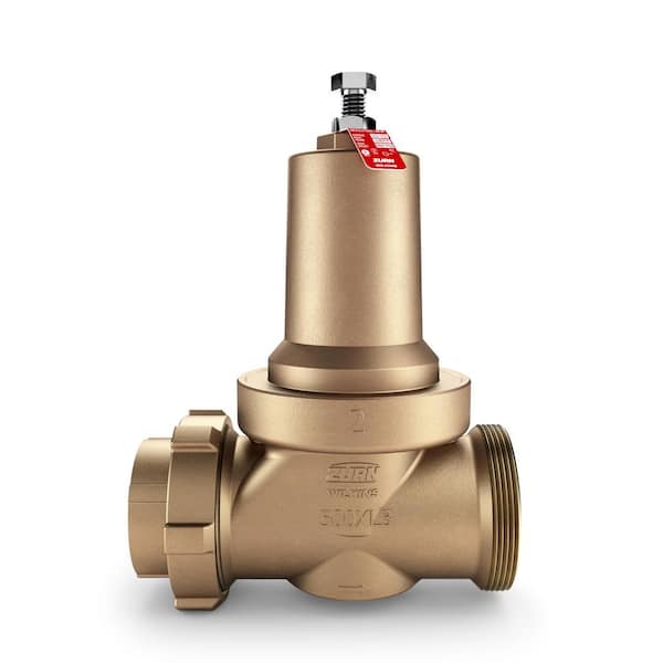
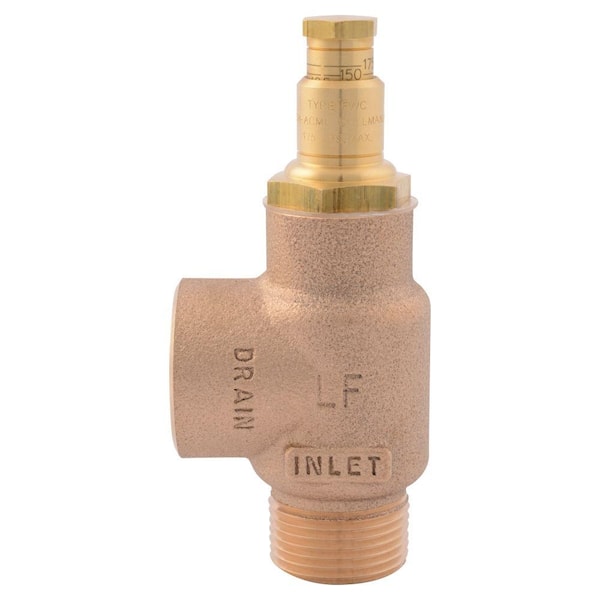
NABIC ®COMBINED PRESSURE &TEMPERATURE RELIEF VALVEFig 500TAPPLICATIONSThe Fig 500T Combined Pressure &Temperature Relief Valve has been designedfor use on unvented hot water supply systems,where protection against excess temperatureis required in addition to pressure protection.Pressure and temperature elements of thevalve operate independently, therebyproviding dual safety protection in the onevalve.DIMENSIONSCONSTRUCTIONThe Fig 500T is of gunmental construction,with diaphragm protected working parts andresilient viton seating. All wetted parts aremanufactured from dezincification resistantmaterials, approved by the Water RegulationsAdvisory Scheme for use on potable water.Inlet and outlet connections are of equal sizeand threaded to BS 21, with the inletconnection male and the outlet female. Forother specific technical requirements consultNabic technical department.FEATURESR●RESILIENT VITON SEATING DESIGNCB●HIGH DISCHARGE CAPACITY●POWERFUL THERMOSTATRD●DUAL SAFETY PROTECTIONA●DIAPHRAGM PROTECTED WORKINGPARTSSIZE R A B C DDN BSP mm mm mm mm●SAFE MANUAL TESTING15 3/4 34 48 230 81BODY MATERIAL: GUNMETAL●EASY INSPECTION AND CLEANING20 1 39 47 240 81MAXIMUM SET PRESSURE: 12.5 bar●PRESSURE SETTING LOCKED25 1 1 /4 45 56 260 81MAXIMUM TEMPERATURE: 95 deg C& SEALED32 1 1 /2 54 62 350 127MAXIMUM WORKING TEMP: 75 deg C● DESIGNED AND TESTED TO BS 675940 2 64 71 400 12750 2 1 /2 76 82 430 127●WATER REGULATIONS ADVISORYSCHEME APPROVED PRODUCTNABIC ®
DISCHARGE CAPACITIESThe discharge capacity of a safety valve must be equal to or greater than the output of the boiler or system it is protecting.Two methods of sizing are employed for combined pressure & temperature relief valves; one,based on the pressure element of the valve, the other, based on the temperature element.To ensure that the correct method is used, reference should be make to the relevent BS specification to the design of theboiler or system. If in doubt, choose the method which produces the lower rating.TEMPERATURE RATINGSIZE DN15 DN20 DN25 DN32 DN40 DN50kW 25 45 65 105 165 255To convert to Btu/hr multiply by 3400The above discharge capacities represent approximately 45% of the relief capability of the value, when steam at a pressureof 1 bar causes the thermostat to open the valve.SETPRESSUREBARPRESSURE RATINGkWDN15 DN20 DN25 DN32 DN40 DN501.0 46 81 127 208 326 5091.5 58 103 160 263 411 6422.0 70 124 194 318 496 7752.5 82 145 227 372 581 9083.0 94 167 260 427 667 10424.0 118 209 327 536 837 13085.0 142 252 394 645 1008 15756.0 166 295 460 754 1178 18417.0 190 337 527 863 1349 21088.0 214 380 594 973 1520 237410.0 262 465 727 1191 1861 290712.5 322 572 893 1464 2287 3574To convert to Btu/hr multiply by 3400The above discharge capacities have been calculated in accordance with BS 6759:Part 1, using a derated coefficientof discharge (Kdr) of 0.479. They represent the steam relief capability of the pressure elementof the valve at 10% overpressure.NABIC ®
Safety valves and pressure relief valves are crucial for one main reason: safety. This means safety for the plant and equipment as well as safety for plant personnel and the surrounding environment.
Safety valves and pressure relief valves protect vessels, piping systems, and equipment from overpressure, which, if unchecked, can not only damage a system but potentially cause an explosion. Because these valves play such an important role, it’s absolutely essential that the right valve is used every time.
The valve size must correspond to the size of the inlet and discharge piping. The National Board specifies that the both the inlet piping and the discharge piping connected to the valve must be at least as large as the inlet/discharge opening on the valve itself.
The connection types are also important. For example, is the connection male or female? Flanged? All of these factors help determine which valve to use.
The set pressure of the valve must not exceed the maximum allowable working pressure (MAWP) of the boiler or other vessel. What this means is that the valve must open at or below the MAWP of the equipment. In turn, the MAWP of the equipment should be at least 10% greater than the highest expected operating pressure under normal circumstances.
Temperature affects the volume and viscosity of the gas or liquid flowing through the system. Temperature also helps determine the ideal material of construction for the valve. For example, steel valves can handle higher operating temperatures than valves made of either bronze or iron. Both the operating and the relieving temperature must be taken into account.
Back pressure, which may be constant or variable, is pressure on the outlet side of the pressure relief valve as a result of the pressure in the discharge system. It can affect the set pressure of the upstream valve and cause it to pop open repeatedly, which can damage the valve.
For installations with variable back pressure, valves should be selected so that the back pressure doesn’t exceed 10% of the valve set pressure. For installations with high levels of constant back pressure, a bellows-sealed valve or pilot-operated valve may be required.
Different types of service (steam, air, gas, etc.) require different valves. In addition, the valve material of construction needs to be appropriate for the service. For example, valves made of stainless steel are preferable for corrosive media.
Safety valves and relief valves must be able to relieve pressure at a certain capacity. The required capacity is determined by several factors including the geometry of the valve, the temperature of the media, and the relief discharge area.
These are just the basic factors that must be considered when selecting and sizing safety valves and relief valves. You must also consider the physical dimensions of the equipment and the plant, as well as other factors related to the environment in which the valve will operate.

The term ‘safety valve’ would typically encompass relief valves, pressure-relief valves and safety relief valves, and this ‘pressure equipment’ – as it is referred to in EU directives – is classified by group according to the level of hazard. Fluids used in building services engineering would most likely be those referred to in the standards as being in group 2 (whereas group 1 is for those classified as ‘hazardous’). The fluid group would normally be used as part of the assessment of risk ‘category’; however, general purpose safety valves will, in any case, fall under the most stringent category 4, which defines the level of design and production quality control to ensure conformity that allows a safety device to bear the legally required CE mark.
In the UK, specific requirements for system safety are principally encompassed by the Pressure Equipment (Safety) Regulations 20161 and the Simple Pressure Vessels (Safety) Regulations 20162 that implement Directives 2014/68/EU, the Pressure Equipment Directive (PED), and 2014/29/EU, the Simple Pressure Vessels Directive (SPVD). The regulations specifically come into play when the systems are operating at pressures greater that 50kPa (0.5bar, 5.1m water head).
The recently revised part 1 of Safety devices for protection against excessive pressure, BS EN ISO 4126:2019, specifies the general requirements for safety valves and the testing techniques for valves set at pressures of 0.1bar gauge and above. (This standard supersedes the withdrawn, but oft quoted, UK standard BS 6759.3) ISO 4126 has 11 parts that consider the different requirements to provide against excessive pressure. It describes a safety valve as ‘a valve which automatically, without the assistance of any energy other than that of the fluid concerned, discharges a quantity of the fluid so as to prevent a predetermined safe pressure being exceeded, and which is designed to re-close and prevent further flow of fluid after normal pressure conditions of service have been restored’.
A safety valve may provide protection against hazards arising from a number of scenarios. This could, for example, be a blocked vessel or pipework discharge; excessive heat from external sources, such as the sun, or other equipment that can cause the fluid within the pipework to expand; system thermal expansion from heat fluctuations beyond the expected design conditions; and failure of a pipeline component, such as an ineffective, failed or tampered control valve or other component that may prevent adequate, or any, discharge.
When evaluating the expected performance of a valve, some terms are commonly used to describe valve operation, as shown in Table 1 and illustrated in Figure 1.
Direct spring safety valves, as illustrated in Figure 2 and Figure 3A, are commonly used within building services systems. The spring is precompressed to apply force downwards on the disc, holding it onto the seat to maintain a pressure-tight seal. If the system pressure increases beyond a predetermined value, it overcomes the spring force and flow commences.
Figure 3b shows a combined temperature- and pressure-relief valve. In addition to providing pressure protection, this valve also features a thermostatic probe, which gives protection against excessive temperature. If the system pressure or temperature increases beyond the set point, the spring force is overcome and flow commences. Each of these lift mechanisms works independently of each other, but are managed through a common seat and disc arrangement. Typically, the valve can be temperature set to between -20°C to 95°C.
The operation of a safety valve can be considered in three states: in equilibrium, open, and closed. When the closing forces acting to close the safety valve are in balance with the opening forces acting to open it, it is in a state of equilibrium (defined in ISO 4126 as the ‘set pressure’). This is illustrated in Figure 4 for a safety valve where the valve seat and disc are just in contact. In this position, there is no flow, but flow will commence if the system pressure rises.
When fully open, as shown in Figure 5, the safety valve can pass the maximum/rated capacity at the specified overpressure (not the set pressure). For the safety valve to remain open, the force from the fluid on the underside of the disc must exceed the equilibrium force (the applied spring and backpressure force).
A valve will be fully closed when the closing force (spring + backpressure) exceeds the opening force. The term blowdown is used to represent the difference between the set pressure and reseating pressure of a safety valve, expressed as a percentage of the set pressure, so…
Safety valves should be carefully selected and sized for the specific application to ensure that they have sufficient discharge capability. Sizing will directly influence valve performance. For example, oversized valves will partially lift at set pressure and then reseat. This can potentially cause ‘chattering’ of the disc and damage to the seat and disc surfaces. Oversized valves may also lead to the release of excessive amounts of fluid.
There are three main considerations when sizing and selecting an appropriate, and correctly sized, safety valve – application, set pressure and discharge capacity.
Consideration of the application includes the location of the safety valve. For example, it may be employed to protect a boiler, to relieve a pump overpressure, or to ensure the integrity of a vessel (tank). The fluid that is in the system – in building services it is likely to be water, air or steam – will influence the choice of valve material and design.
The set pressure of the safety valve will need to be established. If the required set pressure has not been specified at the time of sizing, this can be calculated from the working pressure of the system (at the point in the system where the valve is to be installed). If the working pressure is known, the set pressure may be established using empirical data established by manufacturers and building operators. So, for example, a manufacturer4 recommends that, for a liquid/water system, set pressure would be the working pressure +0.7bar, or the working pressure x 1.1 (whichever is the greater).
Careful consideration of the requirements is needed where the only available information is the maximum pressure rating/output of a heat source, such as when protecting a system with a boiler or plate heat exchanger. This value is simply a statement of the maximum capability of the appliance and it is very unlikely to represent the actual working pressure. The UK’s Health and Safety Executive (HSE) publishes a useful approved code of practice and guidance document – L122 Safety of pressure systems5 – which cautions that the terminology used for different types of systems will vary. For example, the safe operating limit for a boiler may be known as the ‘maximum permissible working pressure’, whereas the safe operating limits for refrigeration plant will be expressed in terms of minimum and maximum temperatures. In cases of doubt, or where information is not clear, it is recommended that further detailed information should be sought from the manufacturer or other competent organisation. As the safety valve is intrinsically part of the whole system, the set pressure of a safety valve must not exceed the design pressure of the system being protected, and it should be suitably selected with reference to the working pressure of the system that is being protected by the safety device.
The position of a safety valve in the system can directly affect its performance and discharge capabilities. As highlighted in BS ISO 4126-9:2008 (the part of the standard that considers the application and installation of safety devices typically used in building services systems) ‘operating problems can occur in pressure relief because of the selection of an inappropriate device or because a correctly selected device is adversely affected by improper handling, wrong installation or lack of maintenance’. The experience of manufacturers and guidance from documents such as BS ISO 4126-9 will provide essential knowledge to ensure correct installation of safety valves. If valves are mounted in other than a vertical position, the valve manufacturer’s recommendations must be considered. If fitted with a test lever (such as shown in Figures 2-7), this should be positioned uppermost, ensuring that it is accessible.
The inlet and outlet piping must be properly supported to ensure that no unacceptable mechanical loads are transmitted to the safety valve and, similarly, the piping must be able to withstand the effects of the reaction forces when the valve discharges. The pipework design should accommodate thermal stresses induced in the inlet and outlet piping. Vibration stresses, including those caused by poor flow geometry in the inlet and outlet piping systems, must be minimised to avoid premature valve failure. Recommendations suggest that piped connections from the protected system to the safety valve should have a pressure drop of no more than 3% of the pressure at the valve when it is operating with maximum discharge.
Flow-control valves must not be installed between the safety valve and the system that is being protected. As noted in BS ISO 4126-9, safety valves may be manually isolated from the equipment if the source of pressure, which could lead to an unsafe condition, is simultaneously isolated from the equipment to be protected. Safety devices undergoing maintenance should be isolated from operating equipment, but it is essential that operating equipment should continue to be fully protected against potential sources of overpressure. Any provision made for isolating any one safety device (for example, for testing or servicing) must ensure that the remaining safety device(s) connected to the equipment can provide the full relief capacity required at any time. This may use such devices as manual three-way valves, changeover valves, mechanical interlocks, and interlocked valves.
Connection details can adversely affect safety valves. The arrangement of the pipework approaching the inlet of the safety valve – such as fittings, bends and lateral connections (as in Figure 6) – can impact its performance, as streamflow regimes will be affected. On the discharge side of the valve, an inverted outlet (as shown in Figure 6 and Figure 7) will create a backpressure on the safety valve disc, because of the head of fluid in the riser, which will affect the set pressure.
Safety valves should be included in a planned maintenance programme to ensure that the device will continue to operate appropriately, the valve life is prolonged, and that the system operation complies with insurance requirements. Manufacturers will have guidelines on testing and maintenance programmes and procedures. The specific maintenance programme must take heed of the manufacturer’s recommendations, as well as account for the particular conditions of the system and its location.
1 The Pressure Equipment (Safety) Regulations 2016 (UK Statutory Instrument 2016 No.1105)2 The Simple Pressure Vessels (Safety) Regulations 2016 (UK Statutory Instrument 2016 No.1092)3 Withdrawn Superseded UK standard BS 6759-1 1984 Safety valves. Specification for safety valves for steam and water4 NABIC recommendation – direct communication5 Approved Code of Practice and guidance L122 Safety of pressure systems, UK HSE 2014

NABIC have long been recognised as the industry standard for commercial and industrial safety and relief valves for hot water applications. NABIC products are all UK made with castings from the UK and Europe. NABIC products do not have castings from the far east as with many of its competitors.
Flowstar (UK) Limited (Company Number: 01384915, VAT Number: GB 475 448 317) is the largest worldwide stockist of NABIC safety valves and NABIC relief valves. Our NABIC prices are genuine discounts off the official NABIC list price. We have not increased our prices before discounting as on some websites. If you buy NABIC valves on a regular basis we can offer further discount and will price match were possible.
Returns: You need to tell us if you wish to return un-used goods within 14 days of purchase either by phone or email. You then have a further 14 days to return the goods back to us. We aim to process the refund within a few days of receiving them. Please note we charge a 20% restocking fee. This is to cover the work originally carried out setting and testing the valve and also the work we will need to do on its return to get it ready for resale.
The primary purpose of a pressure relief valve is to protect life, property and the environment. Pressure relief valves are designed to open and release excess pressure from vessels or equipment and then close again.
The function of pressure relief valves differs depending on the main type or loading principle of the valve. The main types of pressure relief valves are spring-loaded, weight-loaded and controlled pressure relief valves.
Regardless of the type or load, pressure relief valves are set to a specific set pressure at which the medium is discharged in a controlled manner, thus preventing overpressure of the equipment. In dependence of several parameters such as the contained medium, the set pressure is individual for each safety application.

The Supreme Court has reinforced the theory of the First Amendment as a "safety valve," reasoning that citizens who are free to to express displeasure against government through peaceful protest will be deterred from undertaking violent means. The boundary between what is peaceful and what is violent is not always clear. For example, in this 1965 photo, Alabama State College students participated in a non-violent protest for voter rights when deputies confronted them anyway, breaking up the gathering. (AP Photo/Perry Aycock, used with permission from the Associated Press)
Under the safety valve rationale, citizens are free to make statements concerning controversial societal issues to express their displeasure against government and its policies. In assuming this right, citizens will be deterred from undertaking violent means to draw attention to their causes.
The First Amendment, in safeguarding freedom of speech, religion, peaceable assembly, and a right to petition government, embodies the safety valve theory.
These and other decisions rest on the idea that it is better to allow members of the public to judge ideas for themselves and act accordingly than to have the government act as a censure. The Court has even shown support in cases concerning obscenity or speech that incites violent action. The safety valve theory suggests that such a policy is more likely to lead to civil peace than to civil disruption.
Justice Louis D. Brandeis recognized the potential for the First Amendment to serve as a safety valve in his concurring opinion in Whitney v. California (1927) when he wrote: “fear breeds repression; . . . repression breeds hate; . . . hate menaces stable government; . . . the path of safety lies in the opportunity to discuss freely supposed grievances and proposed remedies; and the fitting remedy for evil counsels is good ones.”


 8613371530291