
natural gas outlet box with safety valve free sample
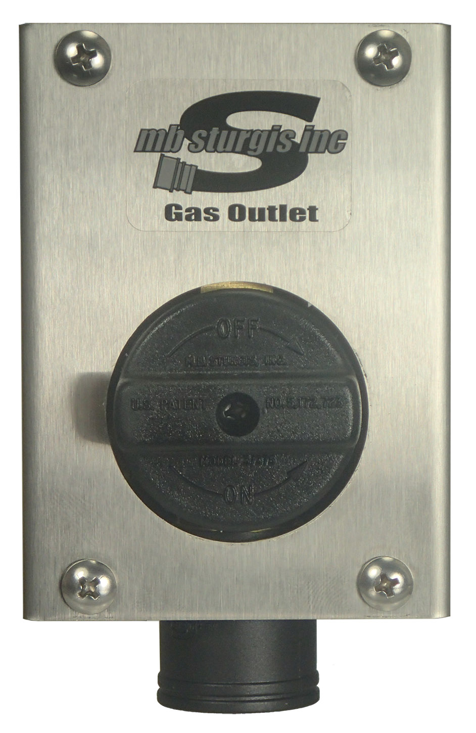
I am an avid shopper at my local big box home store and was disappointed that they didn"t offer a gas version of the water outlet box. Given the time crunch of my project, I was going to just use a water outlet box and switch out the necessary parts to install a gas valve. I am extremely happy that I did not do that. The Ox Box I received is a far superior product than the water outlet box that I purchased. It is much thicker and has additional hardware for mounting. I would highly recommend this product to anyone looking to install a gas line. The recessed nature of the box allows for more room and provides a clean and professional look.
Surface-controlled subsurface safety valves (SCSSVs) are critical components of well completions, preventing uncontrolled flow in the case of catastrophic damage to wellhead equipment. Fail-safe closure must be certain to ensure proper security of the well. However, this is not the only function in which it must be reliable—the valve must remain open to produce the well. Schlumberger surface controlled subsurface safety valves exceed all ISO 10432 and API Spec 14A requirements for pressure integrity, leakage acceptance criteria, and slam closure.
Through decades of innovation and experience, Schlumberger safety valve flapper systems are proven robust and reliable. The multizone dynamic seal technology for hydraulic actuation of subsurface safety valves is a further improvement in reliability performance when compared with traditional seal systems in the industry.
The multizone seal technology was developed and proved with exhaustive verification and validation of reliability, longevity, and performance. The validation methodology utilized a unique sapphire crystal bore, enabling the design team to view the seal’s dynamic and static performance in real time while simulating wellbore pressure and temperature conditions.
The multizone seal technology is currently available in the GeoGuard high-performance deepwater safety valves, which is validated to API Spec 14A V1 and V1-H.
The primary purpose of a safety valve is to protect life, property and the environment. Safety valves are designed to open and release excess pressure from vessels or equipment and then close again.
The function of safety valves differs depending on the load or main type of the valve. The main types of safety valves are spring-loaded, weight-loaded and controlled safety valves.
Regardless of the type or load, safety valves are set to a specific set pressure at which the medium is discharged in a controlled manner, thus preventing overpressure of the equipment. In dependence of several parameters such as the contained medium, the set pressure is individual for each safety application.

The failure to supply natural gas upon demand can cause irreparable damage to a company’s corporate image in the 21st Century. Consistent and continuous pipeline operations are key and critical factors in today’s natural gas pipeline industry. The competitive nature of the business, together with the strict rules and regulations of natural gas supply, mandate that companies stay on top of all operational parameters that could cause interruption or complete shut-down of the natural gas supply to customers. Identifying what may ultimately cause problems is a first step to controlling and eliminating those problems for the supplier.
The natural phenomenon of freezing is a common occurrence in the operation of a natural gas pipeline system. Whether the gas is “produced gas” from a crude oil well, or “natural gas” from a gas well, the possibility for hydrates and the resultant problems, is real. Freezing is a potential and serious problem starting at the production wellhead through the last point in the customer delivery system. The occurrence of freezing is continuously reduced each step of the way, but care must be taken at each and every step to assure smooth operational conditions and satisfied consumers at the end of the line.
Freezing not only affects the pipeline itself but is also a significant contributor to measurement errors and to instrumentation upsets or failures. All of these potential issues will ultimately affect the overall pipeline operation and may have a major impact on the profitability of your company. The relatively small cost of prevention will produce large dividends from a successful and uninterrupted natural gas supply.
Each situation differs from location to location. For this reason, there are several methods to combat freezing in the total spectrum of the natural gas industry.
In searching for potential freezing problems the operator should be aware of the quality of gas, the composition of the gas, piping designs, regulation or restriction points, instrument take-off points and similar pipeline operation features that can and will impact the occurrence of freezing.
Production and gathering systems are typically laden with water vapor thus increasing the likelihood of freezing problems. Transmission lines should be less likely to be affected by freezing since the gas has typically been through a treatment facility and a majority of the liquids have been removed. Typical water allowance is 7 lbs. per million Std. Cu. Ft., (roughly 1 US Gallon) which is considered to be relatively dry gas. Within the normal Local Distribution Company (LDC), the problems associated with freezing SHOULD be almost non-existent. However, price and demand of natural gas can also have an overriding effect on the presence of liquids in the pipeline, as was experienced in 2001 and 2002 in many regions of the United States.
Hydrates can also form into “balls of ice” at temperatures well above freezing. Hydrate crystallization can occur with H2O and hydrocarbons at 60° F and cause damage or completely seal off pipeline flow. This natural phenomenon is unrelated to “freezing” as we know it, but can be addressed in the same manner as standard freezing problems.
There are several points to remember when discussing freezing and they are discussed in the GAS ENGINEERS HANDBOOK, Section 4, Chapter 8, ”Gas Hydrates and Gas Dehydration.” Two major ones to keep in mind are:
In a practical case you can have gas flowing in the pipeline at 60 degrees Fahrenheit and 700 psi and have no evidence of freezing. If you pass through a regulator station and cut the pressure to 225 psi, the flowing temperature at the point of regulation will drop 33 degrees Fahrenheit to approximately 27 degrees Fahrenheit. If the gas stream is saturated with water vapor and condensate, you will quickly experience the freezing concerns we are discussing. The gas stream is the same, but conditions have changed and your problems have commenced to affect your operations.
In order to correct freezing problems that occur under differing operational conditions, solutions must be designed for the particular needs of the location where the problem exists. Each solution may have specific advantages and disadvantages for the operator. The single most important aspect for any methodology is consistent operation and maintenance with the chosen approach to the freezing problem.
One of the most common methods of dehydration for large volumes of gas is Triethylene glycol absorption or regenerative method. Gas passes through the glycol inside a vessel called a contactor. The object is to remove the water (mist, vapor or free water) to a point where the water vapor dew point of the gas will not be attained at the highest pressure and lowest temperature of the pipeline system. Pure glycol enters in the top of the contactor where the driest gas is leaving the vessel. Dry gas does not want to release H2O, therefore the most aggressive action occurs with the purest glycol and driest gas. The saturated glycol is at the bottom where the wet gas enters, but it still pulls H2O from the saturated gas flow. Glycol rains down through the tower hitting trays and allowing for additional contact with the gas. The ideal tower operating temperature is from 80° F to 110°F.
Colder climates frequently dictate a dehydration system in a natural gas system, but even warmer climates may require central dehydration due to pressure, temperature and gas composition. A producer can basically look at three dehydration options.
This system is a low cost system with continuous operation and minimal pressure loss across the unit, thus making it a money saver in several areas of operation. The drawbacks can be glycol carry-over during surges, contamination by solid particles and inefficiency during fluctuating flow rates.
A very efficient method of water removal is the dry bed or molecular sieve method. The gas is passed through large towers of solid particles and the molecular sieve absorbs the water very aggressively. Very dry gas over a wide range of flow rates can be attained by this method. Eventually, the sieve becomes saturated and must be regenerated. The stream must be switched to a second tower and hot gas is introduced to the original unit to evaporate the water and dry the sieve.
Cool gas is then used to cool the desiccant and the tower is ready for re-use. This cycle is repeated until the desiccant has degenerated and is no longer effective. While this method produces very dry gas and has several positive operating characteristics, it is more costly than typical glycol systems and more complex to operate.
Methanol (an anti-freeze type solution) injection is a very common practice for freeze protection for smaller systems and specific locations. The methanol is injected into the gas stream by chemical injection pumps or enters the pipeline by methanol drips and effectively lowers the freeze point of the gas. The amounts of methanol required can be calculated by using available tables for specific applications.
A small volume methanol tower can also be fabricated allowing small volumes of gas to pass through the methanol for treatment. Because of the sensitive nature of many pneumatic controllers, this method is occasionally used to prevent freeze-ups in these devices and to prevent liquid migration into small orifices and passages. An additional filter is often used to ensure that the methanol is not carried over into the instrumentation.
Heat is a logical solution to freezing problems. It is also a costly approach to the problem for several reasons. Obviously, if the gas is never allowed to reach freezing temperatures, ice cannot form and will not be present. The water will likely not be removed, which remains an issue for operations and contracts, but the freezing is eliminated. The problems with heat are that it is expensive equipment to install, it requires additional fuel (energy and revenue) to produce the heat, and the heat will not remain effective as it travels down the pipeline and away from the heat source.
Heat is also a potential hazard as it can provide an ignition point for the gas. Safety and special emphasis on proper application is a must when using a heat source. The most common application of heat for freeze protection is in a specific and direct situation, as in the case of a regulator valve body. The pressure drop at the regulator is the only problem point and therefore, can be the only specific location where freeze protection is required.
During the design phase of the piping system and through to the instrumentation system, certain steps can be taken to reduce the negative effects of freezing problems. Piping configurations that would allow for liquid accumulation should be avoided if at all possible. Drainage should slope towards drain fittings located at low spots. Where possible, use ball valves and large diameter, (1/2” for ½” taps) tubing for instrument feed lines and sensing lines. Avoid restrictions where flow will occur. Tubing runs should slope back toward the pipeline and you should have a leak free instrument system. Liquids, if they are present, will be drawn towards the leak. If you avoid creating traps and liquid drop out areas, your freezing problems will be minimized.
Occasional slugs of liquid can damage or even “shut in” many instrument supply systems. Where this slug potential exists or in cases where liquid is a severe problem in the gas supply used for instrumentation, drip pots and coalescers can effectively knockout or reduce the water and condensate in a small volume instrument supply system. If the problem is excessive, an automatic liquid dump designed for instrumentation can be extremely helpful. Whereas the drip pot requires routine manual draining, the automatic liquid dump will act as a drip pot collection vessel with a coalescer and as a result of an internal float assembly and pivot valve, will automatically release the collected liquid to a lower pressure point.
Many instrument controllers and other sensitive measurement equipment powered by instrument gas supply need the highest level of clean and dry instrument supply that is attainable. In some cases a good linear polyethylene filter can provide adequate protection. But the most common solution for instrument supply gas is the filter dryer.
These units are designed for high pressure applications with removable media cartridges. While various types of media are available from molecular sieve to special H2S removal media, most are equipped with a combination desiccant and charcoal filter cartridge. Coupled with providing extremely dry and fresh gas, the ancillary filtration elements in the cartridge provide for 2-4 micron protection as well. For critical locations, these dryers can be manifolded with offset regulators to provide uninterrupted service. If one side of the system shuts in due to freezing, the other side takes over the supply while the original inlet side thaws out. The filter dryer can be equipped with “tattle-tale eyes” that indicate saturation of the desiccant and the need for a cartridge replacement. These systems are designed for maximum protection with typical flow rates of around 60-70 cfm. Where a failure in instrument supply would create severe problems, this style dehydration assembly is an ironclad solution for continuous service.
Recently, several manufacturers have combined regulation, filtration, heat and manifold convenience into multi-pressure, single stand alone Instrument Tower Package Systems for the more complex instrument supply needs. They are primarily designed for pneumatic controllers and process control instrumentation systems but can be utilized in many areas that require a clean, dry, regulated and uninterrupted gas or instrument air supply.
Natural gas systems, from mainstream pipeline flow to low pressure instrumentation, are subject to freezing conditions. Through careful planning and evaluation of your specific application, proper selection of available options, and a good routine maintenance program, this industry wide concern can be controlled and minimized. If these issues are ignored, the cost of dealing with the aftermath is almost always more expensive than the preventative action that could have been taken. Avoidance of freezing problems is a good investment and adds to the profitability of your company.
“Freeze Protection for Instrumentation Controls, Controllers, Control Valves and Measurement Equipment”, T.F. Welker, Presented at Appalachian Gas Measurement Short Course, Pittsburgh, PA, 2000
In addition to gas solenoid valves, we also offer a large range of AIR/GAS line accessories such as sectional valves (lockable or not), air/gas pressure switches with incremental pressure (low or high pressure), manometers and safety boxes to protect gas solenoid valves.
A sectional valve is the first element in an AIR/GAS line. It is available in two versions: lockable or not. This safety unit is very important as it enables the gas supply shut down at a precise point. Without a sectional valve, it is sometimes required to shut down the gas supply at the reducing station for any repair which considerably increases the technical intervention cost: need to purge a large section.
Gas pressure switches are also safety units at low or high pressure. They are designed to control the minimal presence of gas (mini gas pressure switch) or a gas overpressure (maxi gas pressure switch). They directly act on the installation’s safety loop.
The logical approach would be for the gas safety valve to be implemented outdoors, thus avoiding any explosion risk in case of gas leak (at the connection point for example). A safety box – colored in red for a better view – protects safety units from the weather or bad behaviors (lock with key).


 8613371530291